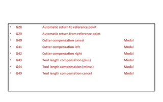
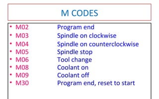
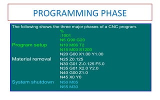
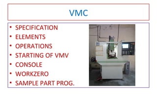
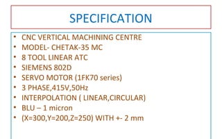
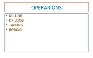
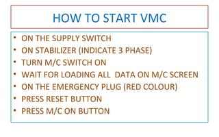
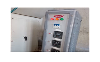
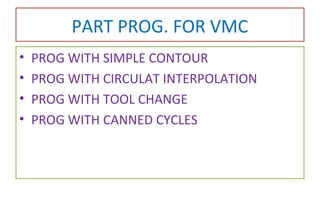
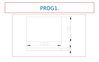
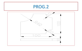
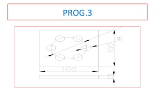
CNC MACHINE TRAININGCNC MACHINE TRAINING
MECHANICAL DEPARTMENT
DR. S & S S GHANDHY COLLEGE
SURAT
MECHANICAL DEPARTMENT
DR. S & S S GHANDHY COLLEGE
SURAT
PREPARED & PRESENTED BY:
TARUN B PATEL
PREPARED & PRESENTED BY:
TARUN B PATEL
OUTLINE
• INTRODUCTION OF CNC
• CONSTRUCTIONAL FEATURES
• PROGRAMING
• DEMOSTRATION OF VMC
• HANDS ON PRACTICE
OBJECTIVE
• TO FAMILIAR WITH VMC
• TO MAINTAIN THE VMC
INTRO OF CNC
• Numerical Control can be defined as an operation of machine
tools by means of specifically coded instructions to the machine
control system.
Setup time reduction
Lead time reduction
Accuracy and repeatability
Contouring of complex shapes
Simplified tooling and work holding
Consistent cutting time
General productivity increase
CONSTRUCTIONAL FEATURES
• PART PROGRAM
• PROGRAM INPUT DEVICE
• MACHINE CONTROL UNIT
• DRIVE SYSTEM ( SERVO MOTOR, BALL SCREW)
• MACHINE TOOL
• FEEDBACK SYSTEM
• ATC
• APC
• AUTOMATIC LUBRICATION
• HEAT REMOVAL SYSTEM
• SWARF REMOVAL
• SAFETY
CNC BLOCK DIAGRAM
CONTROL SYSTEM
AXIS IDENTIFICATIONS
For flat and prismatic
(block-like) parts:
Milling and drilling o/p.
For rotational parts:
Turning operations
Only x- and z-axes
PROGRAMMING
• PROGRAMMING FORMATS
– Tab Sequential Format
– Fixed Format
– Word Address Format
CNC SYSTEM
Format
N10 G02 M03 X10 Y-10 Z5 R10 I00 J05 K10 F200 S1000 EOB
G CODES
• G00 Positioning in rapid Modal
• G01 Linear interpolation Modal
• G02 Circular interpolation (CW) Modal
• G03 Circular interpolation (CCW) Modal
• G04 Dwell
• G90 ABSOLUTE DIMENTIONING MODAL
• G91 INCREMENTAL DIMENTIONING MODAL
• G54-G59 Workpiece coordinate settings Modal
• G20/G70 Inch units Modal
• G21/G71 Metric units Modal
• G28 Automatic return to reference point
• G29 Automatic return from reference point
• G40 Cutter compensation cancel Modal
• G41 Cutter compensation left Modal
• G42 Cutter compensation right Modal
• G43 Tool length compensation (plus) Modal
• G44 Tool length compensation (minus) Modal
• G49 Tool length compensation cancel Modal
M CODES
• M02 Program end
• M03 Spindle on clockwise
• M04 Spindle on counterclockwise
• M05 Spindle stop
• M06 Tool change
• M08 Coolant on
• M09 Coolant off
• M30 Program end, reset to start
PROGRAMMING PHASE
VMC
• SPECIFICATION
• ELEMENTS
• OPERATIONS
• STARTING OF VMV
• CONSOLE
• WORKZERO
• SAMPLE PART PROG.
SPECIFICATION
• CNC VERTICAL MACHINING CENTRE
• MODEL- CHETAK-35 MC
• 8 TOOL LINEAR ATC
• SIEMENS 802D
• SERVO MOTOR (1FK70 series)
• 3 PHASE,415V,50Hz
• INTERPOLATION ( LINEAR,CIRCULAR)
• BLU – 1 micron
• (X=300,Y=200,Z=250) WITH +- 2 mm
OPERARIONS
• MILLING
• DRILLING
• TAPPING
• BORING
HOW TO START VMC
• ON THE SUPPLY SWITCH
• ON STABILIZER (INDICATE 3 PHASE)
• TURN M/C SWITCH ON
• WAIT FOR LOADING ALL DATA ON M/C SCREEN
• ON THE EMERGENCY PLUG (RED COLOUR)
• PRESS RESET BUTTON
• PRESS M/C ON BUTTON
WORK ZERO
PART PROG. FOR VMC
• PROG WITH SIMPLE CONTOUR
• PROG WITH CIRCULAT INTERPOLATION
• PROG WITH TOOL CHANGE
• PROG WITH CANNED CYCLES
PROG1.
PROG.2
PROG.3
•THANK YOU

Cnc machine training

  • 1.
    CNC MACHINE TRAININGCNCMACHINE TRAINING MECHANICAL DEPARTMENT DR. S & S S GHANDHY COLLEGE SURAT MECHANICAL DEPARTMENT DR. S & S S GHANDHY COLLEGE SURAT PREPARED & PRESENTED BY: TARUN B PATEL PREPARED & PRESENTED BY: TARUN B PATEL
  • 2.
    OUTLINE • INTRODUCTION OFCNC • CONSTRUCTIONAL FEATURES • PROGRAMING • DEMOSTRATION OF VMC • HANDS ON PRACTICE
  • 3.
    OBJECTIVE • TO FAMILIARWITH VMC • TO MAINTAIN THE VMC
  • 4.
    INTRO OF CNC •Numerical Control can be defined as an operation of machine tools by means of specifically coded instructions to the machine control system. Setup time reduction Lead time reduction Accuracy and repeatability Contouring of complex shapes Simplified tooling and work holding Consistent cutting time General productivity increase
  • 5.
    CONSTRUCTIONAL FEATURES • PARTPROGRAM • PROGRAM INPUT DEVICE • MACHINE CONTROL UNIT • DRIVE SYSTEM ( SERVO MOTOR, BALL SCREW) • MACHINE TOOL • FEEDBACK SYSTEM • ATC • APC • AUTOMATIC LUBRICATION • HEAT REMOVAL SYSTEM • SWARF REMOVAL • SAFETY
  • 6.
  • 7.
  • 8.
  • 9.
    AXIS IDENTIFICATIONS For flatand prismatic (block-like) parts: Milling and drilling o/p. For rotational parts: Turning operations Only x- and z-axes
  • 10.
    PROGRAMMING • PROGRAMMING FORMATS –Tab Sequential Format – Fixed Format – Word Address Format CNC SYSTEM Format N10 G02 M03 X10 Y-10 Z5 R10 I00 J05 K10 F200 S1000 EOB
  • 11.
    G CODES • G00Positioning in rapid Modal • G01 Linear interpolation Modal • G02 Circular interpolation (CW) Modal • G03 Circular interpolation (CCW) Modal • G04 Dwell • G90 ABSOLUTE DIMENTIONING MODAL • G91 INCREMENTAL DIMENTIONING MODAL • G54-G59 Workpiece coordinate settings Modal • G20/G70 Inch units Modal • G21/G71 Metric units Modal
  • 12.
    • G28 Automaticreturn to reference point • G29 Automatic return from reference point • G40 Cutter compensation cancel Modal • G41 Cutter compensation left Modal • G42 Cutter compensation right Modal • G43 Tool length compensation (plus) Modal • G44 Tool length compensation (minus) Modal • G49 Tool length compensation cancel Modal
  • 13.
    M CODES • M02Program end • M03 Spindle on clockwise • M04 Spindle on counterclockwise • M05 Spindle stop • M06 Tool change • M08 Coolant on • M09 Coolant off • M30 Program end, reset to start
  • 14.
  • 15.
    VMC • SPECIFICATION • ELEMENTS •OPERATIONS • STARTING OF VMV • CONSOLE • WORKZERO • SAMPLE PART PROG.
  • 16.
    SPECIFICATION • CNC VERTICALMACHINING CENTRE • MODEL- CHETAK-35 MC • 8 TOOL LINEAR ATC • SIEMENS 802D • SERVO MOTOR (1FK70 series) • 3 PHASE,415V,50Hz • INTERPOLATION ( LINEAR,CIRCULAR) • BLU – 1 micron • (X=300,Y=200,Z=250) WITH +- 2 mm
  • 17.
  • 18.
    HOW TO STARTVMC • ON THE SUPPLY SWITCH • ON STABILIZER (INDICATE 3 PHASE) • TURN M/C SWITCH ON • WAIT FOR LOADING ALL DATA ON M/C SCREEN • ON THE EMERGENCY PLUG (RED COLOUR) • PRESS RESET BUTTON • PRESS M/C ON BUTTON
  • 23.
  • 24.
    PART PROG. FORVMC • PROG WITH SIMPLE CONTOUR • PROG WITH CIRCULAT INTERPOLATION • PROG WITH TOOL CHANGE • PROG WITH CANNED CYCLES
  • 25.
  • 26.
  • 27.
  • 28.