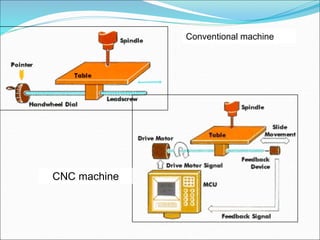
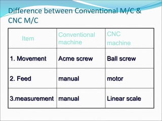
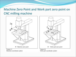
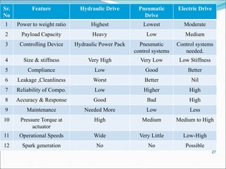
Unit 6 :
CNC Technology and Tooling
 Introduction,
 Construction and working of CNC,
 DNC and machining center.
 CNC axes & drives.
 Automatic Tool Changer (ATC) and Automatic pallet changer
 New trends in Tool Materials,
 Turning tool geometry,
 Tool inserts (and uncoated),
 Modular tooling system for Turning. Milling tooling systems,
 Tools presetting, Work holding.
1.Introduction to CNC machine
CNC = Computerized Numerical Control
History and Development of
Technology
Conventional M/C
NC M/C
(1948 US Air force,)
CNC M/C
1997  1st commercial NC m/c
“CINCINNATIC HYDROTEL VERTICAL-SPINDLE MACHINE “
History and Development of
Technology
Conventional vs. CNC machine
 Machine Structure
The CNC machine tools are basically built in the same
way as conventional machine tools. The difference lies
in the fact that the machine components relevant for
turning and milling processes are controlled by
computers.
Conventional vs. CNC machine
 Function
Conventional vs. CNC machine
Conventional machine
CNC machine
Difference between Conventional M/C &
CNC M/C
Item
Conventional
machine
CNC
machine
1. Movement Acme screw Ball screw
2. Feed manual motor
3.measurement manual Linear scale
Advantages of CNC
 Flexible, high accuracy
 Short production time
 Complex shapes
 Short setting time
 No skill requirement (programming skill is required)
 Short inspection time/ high quality product
 Low cost
Disadvantages of CNC
 High machine cost
 Complicated maintenance
 Skill & training are required for programming and
maintenance.
 High tooling cost
 Temperature, humidity & dust must be controlled.
Why CNC?
HUMAN  LIMITATION
2. Component and Function of CNC
 Feed drive
 Measuring system  Direct / Indirect
 Work spindle  hydraulic
 Cooling system  reduce heat
 Tool turret
Construction
Feed drive
Measuring
System
Tool change facilities
DNC
 Direct numerical control (DNC) – control of multiple
machine tools by a single (mainframe) computer
through direct connection and in real time
 1960s technology
 Two way communication
 Distributed numerical control (DNC) – network
consisting of central computer connected to machine
tool MCUs, which are CNC
 Present technology
 Two way communication
Distributed Numerical Control
Machine
Control Unit
Machine
Control Unit
Machine
Control Unit
Central
Computer NC Pgms
BTR BTR BTR
Computer Network
3. Coordinate System
3.1 CNC Axes
CNC AXES AND DRIVES
Axes on a CNC lathe
Axes on a CNC milling machine
Zero and reference points on CNC
Zero Point of machine on a CNC lathe
Machine Zero Point and Work part zero point on
CNC milling machine
CNC DRIVES
 Basic function of a CNC machine is to provide
automatic and precise motion control to its elements
such work table, tool spindle etc.
 Drives are used to provide such kinds of controlled
motion to the elements of a CNC machine tool. A drive
system consists of drive motors and ball lead-screws.
 The control unit sends the amplified control signals to
actuate drive motors which in turn rotate the ball lead-
screws to position the machine table or cause rotation
of the spindle
Sr.
No
Feature Hydraulic Drive Pneumatic
Drive
Electric Drive
1 Power to weight ratio Highest Lowest Moderate
2 Payload Capacity Heavy Low Medium
3 Controlling Device Hydraulic Power Pack Pneumatic
control systems
Control systems
needed.
4 Size & stiffness Very High Very Low Low Stiffness
5 Compliance Low Good Better
6 Leakage ,Cleanliness Worst Better Nil
7 Reliability of Compo. Low Higher High
8 Accuracy & Response Good Bad High
9 Maintenance Needed More Low Less
10 Pressure Torque at
actuator
High Medium Medium to High
11 Operational Speeds Wide Very Little Low-High
12 Spark generation No No Possible
27
 In CNC, usually AC, DC, servo and stepper electrical
drives are used. The various drives used in CNC
machines can be classified as:
 a. Spindle drives to provide the main spindle power for
cutting action.
 b. Feed drives to drive the axis.
 The spindle drives are used to provide angular motion to the
workpiece or a cutting tool. Figure shows the components of a
spindle drive.
 These drives are essentially required to maintain the speed
accurately within a power band which will enable machining
of a variety of materials with variations in material hardness.
 The speed ranges can be from 10 to 20,000 rpm. The machine
tools mostly employ DC spindle drives. But as of late, the AC
drives are preferred to DC drives due to the advantage of
microprocessor-based AC frequency inverter.
 High overload capacity is also needed for unintended overloads
on the spindle due to an inappropriate feed.
Feed Drives
Fig. Typical feed drive
The requirements of an ideal feed drive
 • The feed motor needs to operate with constant
torque characteristics to overcome friction and
working forces.
 • The drive speed should be extremely variable with a
speed range of about 1: 20000, which means it should
have a maximum speed of around 2000 rpm and at a
minimum speed of 0.1 rpm.
 • The feed motor must run smoothly.
 • The drive should have extremely small positioning
resolution.
 Variable speed DC drives are used as feed drives in CNC
machine tools. However now-a-days AC feed drives are
being used.
Automatic Tool Changer (ATC) and Automatic
pallet changer(APC)
 Machining centers are used to carry out multiple operations
like drilling, milling, boring etc. in one set up on multiple faces
of the workpiece.
 These operations require a number of different tools. Tool
changing operation is time consuming which reduces the
machine utilization.
 Hence the tools should be automatically changed to reduce the
idle time. This can be achieved by using automatic tool changer
(ATC) facility. It helps the workpiece to be machined in one
setup which increases the machine utilization and productivity.
Large numbers of tools can be stored in tool magazines. Tool
magazines are specified by their storage capacity, tool change
procedure and shape. The storage capacity ranges from 12 to
200.
Fig. CNC tool changer
 The tools from the magazines and spindle are
exchanged by a tool changer arm . The tool change
activity requires the following motions:
 a. The spindle stops at the correct orientation for the
tool change arm to pick the tool from the spindle.
 b. Tool change arm moves to the spindle.
 c. Tool change arm picks the tool from the spindle.
 d. Tool change arm indexes to reach the tool
magazine.
 e. Tool magazine indexes so that the tool from the
spindle can be placed.
 f. The tool is placed in the tool magazine.
 g. The tool magazine indexes to bring the required
tool to the tool change position.
 h. Tool change arm picks the tool from the tool
magazine.
 i. Tool change arm indexes to reach the spindle.
 j. New tool is placed in the spindle.
 k. Tool change arm moves back to its parking position.
Advantages of automatic tool changer
 Increase in operator safety by changing tools
automatically
 • Changes the tools in seconds for maintenance and
repair
 • Increases flexibility
 • Heavy and large multi-tools can easily be handled
 • Decreases total production time
Tool magazines
 Tool magazines are generally employed in CNC drilling
and milling machines. Compared to tool turrets the tool
magazines can hold more number of tools therefore proper
management of tools is essential. Duplication of the tools
is possible and a new tool of same type may be selected
when a particular tool is worn off. The power required to
move the tools in a tool magazine is more in comparison
with that required in tool turrets. The following are some
of the tool magazines used in automation.
 1 Disc or drum type
 2 Chain type
 3 Rack type type
1 Disc or drum type
 The disc type tool magazine rotates to get the desired
tool in position with the tool change arm . Larger the
diameter of the disc/drum more the number of tools it
can hold. It has pockets where tool can be inserted. In
case of drum type magazine which can store large
amount of tools, the pockets are on the surface along
the length. It carries about 12 to 50 tools. If the
number of tools are less the disc is mounted on top of
the spindle to minimize the travel of tool between the
spindle and the disc. If the tools are more then, the
disc is wall mounted or mounted on the machining
center column. If the disc is column mounted then, it
needs an additional linear motion to move it to the
loading station for tool change.
Fig. Drum magazine
2 Chain type
 When the number of tools is more than 50, chain type
of magazines are used .The magazine is mounted
overhead or as a separate column. In chain magazines
the tools are identified either by their location in the
tool holder or by means of some coding on the tool
holder. These types of magazines can be duplicated.
There can be two chain magazines: one is active for
machining and the second magazine is used when the
duplicate tool is needed since the active tool is worn
out.
Fig. Chain magazine
Rack type magazine
 Rack magazines are cost-efficient alternative to usual
tool magazine systems Set-up time can be optimized
by utilizing the racks’ capacity of up to 50 tools. The
high storage capacity of up to 400 tools permits a large
production capacity of varying work pieces without
tool changes. They can also be used to store work
pieces.

CNC FUNDAMENTALS.ppt

  • 1.
    Unit 6 : CNCTechnology and Tooling  Introduction,  Construction and working of CNC,  DNC and machining center.  CNC axes & drives.  Automatic Tool Changer (ATC) and Automatic pallet changer  New trends in Tool Materials,  Turning tool geometry,  Tool inserts (and uncoated),  Modular tooling system for Turning. Milling tooling systems,  Tools presetting, Work holding.
  • 2.
    1.Introduction to CNCmachine CNC = Computerized Numerical Control
  • 3.
    History and Developmentof Technology Conventional M/C NC M/C (1948 US Air force,) CNC M/C 1997  1st commercial NC m/c “CINCINNATIC HYDROTEL VERTICAL-SPINDLE MACHINE “
  • 4.
  • 5.
    Conventional vs. CNCmachine  Machine Structure The CNC machine tools are basically built in the same way as conventional machine tools. The difference lies in the fact that the machine components relevant for turning and milling processes are controlled by computers.
  • 6.
    Conventional vs. CNCmachine  Function
  • 7.
  • 8.
  • 9.
    Difference between ConventionalM/C & CNC M/C Item Conventional machine CNC machine 1. Movement Acme screw Ball screw 2. Feed manual motor 3.measurement manual Linear scale
  • 10.
    Advantages of CNC Flexible, high accuracy  Short production time  Complex shapes  Short setting time  No skill requirement (programming skill is required)  Short inspection time/ high quality product  Low cost
  • 11.
    Disadvantages of CNC High machine cost  Complicated maintenance  Skill & training are required for programming and maintenance.  High tooling cost  Temperature, humidity & dust must be controlled.
  • 12.
  • 13.
    2. Component andFunction of CNC  Feed drive  Measuring system  Direct / Indirect  Work spindle  hydraulic  Cooling system  reduce heat  Tool turret Construction
  • 14.
  • 15.
  • 16.
  • 17.
    DNC  Direct numericalcontrol (DNC) – control of multiple machine tools by a single (mainframe) computer through direct connection and in real time  1960s technology  Two way communication  Distributed numerical control (DNC) – network consisting of central computer connected to machine tool MCUs, which are CNC  Present technology  Two way communication
  • 18.
    Distributed Numerical Control Machine ControlUnit Machine Control Unit Machine Control Unit Central Computer NC Pgms BTR BTR BTR Computer Network
  • 19.
  • 20.
  • 21.
    Axes on aCNC lathe
  • 22.
    Axes on aCNC milling machine
  • 23.
    Zero and referencepoints on CNC
  • 24.
    Zero Point ofmachine on a CNC lathe
  • 25.
    Machine Zero Pointand Work part zero point on CNC milling machine
  • 26.
    CNC DRIVES  Basicfunction of a CNC machine is to provide automatic and precise motion control to its elements such work table, tool spindle etc.  Drives are used to provide such kinds of controlled motion to the elements of a CNC machine tool. A drive system consists of drive motors and ball lead-screws.  The control unit sends the amplified control signals to actuate drive motors which in turn rotate the ball lead- screws to position the machine table or cause rotation of the spindle
  • 27.
    Sr. No Feature Hydraulic DrivePneumatic Drive Electric Drive 1 Power to weight ratio Highest Lowest Moderate 2 Payload Capacity Heavy Low Medium 3 Controlling Device Hydraulic Power Pack Pneumatic control systems Control systems needed. 4 Size & stiffness Very High Very Low Low Stiffness 5 Compliance Low Good Better 6 Leakage ,Cleanliness Worst Better Nil 7 Reliability of Compo. Low Higher High 8 Accuracy & Response Good Bad High 9 Maintenance Needed More Low Less 10 Pressure Torque at actuator High Medium Medium to High 11 Operational Speeds Wide Very Little Low-High 12 Spark generation No No Possible 27
  • 28.
     In CNC,usually AC, DC, servo and stepper electrical drives are used. The various drives used in CNC machines can be classified as:  a. Spindle drives to provide the main spindle power for cutting action.  b. Feed drives to drive the axis.
  • 29.
     The spindledrives are used to provide angular motion to the workpiece or a cutting tool. Figure shows the components of a spindle drive.  These drives are essentially required to maintain the speed accurately within a power band which will enable machining of a variety of materials with variations in material hardness.  The speed ranges can be from 10 to 20,000 rpm. The machine tools mostly employ DC spindle drives. But as of late, the AC drives are preferred to DC drives due to the advantage of microprocessor-based AC frequency inverter.  High overload capacity is also needed for unintended overloads on the spindle due to an inappropriate feed.
  • 30.
  • 31.
    The requirements ofan ideal feed drive  • The feed motor needs to operate with constant torque characteristics to overcome friction and working forces.  • The drive speed should be extremely variable with a speed range of about 1: 20000, which means it should have a maximum speed of around 2000 rpm and at a minimum speed of 0.1 rpm.  • The feed motor must run smoothly.  • The drive should have extremely small positioning resolution.  Variable speed DC drives are used as feed drives in CNC machine tools. However now-a-days AC feed drives are being used.
  • 33.
    Automatic Tool Changer(ATC) and Automatic pallet changer(APC)  Machining centers are used to carry out multiple operations like drilling, milling, boring etc. in one set up on multiple faces of the workpiece.  These operations require a number of different tools. Tool changing operation is time consuming which reduces the machine utilization.  Hence the tools should be automatically changed to reduce the idle time. This can be achieved by using automatic tool changer (ATC) facility. It helps the workpiece to be machined in one setup which increases the machine utilization and productivity. Large numbers of tools can be stored in tool magazines. Tool magazines are specified by their storage capacity, tool change procedure and shape. The storage capacity ranges from 12 to 200.
  • 34.
  • 35.
     The toolsfrom the magazines and spindle are exchanged by a tool changer arm . The tool change activity requires the following motions:  a. The spindle stops at the correct orientation for the tool change arm to pick the tool from the spindle.  b. Tool change arm moves to the spindle.  c. Tool change arm picks the tool from the spindle.  d. Tool change arm indexes to reach the tool magazine.
  • 36.
     e. Toolmagazine indexes so that the tool from the spindle can be placed.  f. The tool is placed in the tool magazine.  g. The tool magazine indexes to bring the required tool to the tool change position.  h. Tool change arm picks the tool from the tool magazine.  i. Tool change arm indexes to reach the spindle.  j. New tool is placed in the spindle.  k. Tool change arm moves back to its parking position.
  • 37.
    Advantages of automatictool changer  Increase in operator safety by changing tools automatically  • Changes the tools in seconds for maintenance and repair  • Increases flexibility  • Heavy and large multi-tools can easily be handled  • Decreases total production time
  • 38.
    Tool magazines  Toolmagazines are generally employed in CNC drilling and milling machines. Compared to tool turrets the tool magazines can hold more number of tools therefore proper management of tools is essential. Duplication of the tools is possible and a new tool of same type may be selected when a particular tool is worn off. The power required to move the tools in a tool magazine is more in comparison with that required in tool turrets. The following are some of the tool magazines used in automation.  1 Disc or drum type  2 Chain type  3 Rack type type
  • 39.
    1 Disc ordrum type  The disc type tool magazine rotates to get the desired tool in position with the tool change arm . Larger the diameter of the disc/drum more the number of tools it can hold. It has pockets where tool can be inserted. In case of drum type magazine which can store large amount of tools, the pockets are on the surface along the length. It carries about 12 to 50 tools. If the number of tools are less the disc is mounted on top of the spindle to minimize the travel of tool between the spindle and the disc. If the tools are more then, the disc is wall mounted or mounted on the machining center column. If the disc is column mounted then, it needs an additional linear motion to move it to the loading station for tool change.
  • 40.
  • 41.
    2 Chain type When the number of tools is more than 50, chain type of magazines are used .The magazine is mounted overhead or as a separate column. In chain magazines the tools are identified either by their location in the tool holder or by means of some coding on the tool holder. These types of magazines can be duplicated. There can be two chain magazines: one is active for machining and the second magazine is used when the duplicate tool is needed since the active tool is worn out.
  • 42.
  • 43.
  • 44.
     Rack magazinesare cost-efficient alternative to usual tool magazine systems Set-up time can be optimized by utilizing the racks’ capacity of up to 50 tools. The high storage capacity of up to 400 tools permits a large production capacity of varying work pieces without tool changes. They can also be used to store work pieces.