Downloaded 186 times

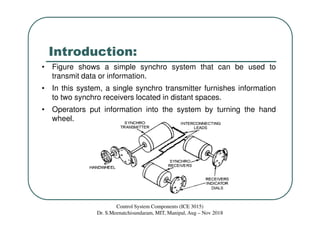
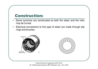

Synchros are electromechanical devices that transmit angular position information electrically. They have a rotor and three stator windings spaced 120 degrees apart. Synchros transmit position data quickly and accurately between equipment. They are classified based on the load as either torque or control synchros. Control synchros handle heavier loads like antennas and launchers. Synchros consist of a rotor that can rotate continuously within stationary stator windings. The rotor receives an excitation voltage and its position induces voltages in the stator windings.