Downloaded 18 times


Load cells convert applied forces like tension, compression, pressure, or torque into electrical signals proportional to the force. The most common types are strain gauge, capacitive, and hydraulic load cells. A load cell works by measuring the deformation or change in an electrical property caused by an applied force. During calibration, load cells are tested incrementally using specific weights to ensure accuracy by evaluating linearity and repeatability. Annual recalibration is recommended best practice for load cell users.
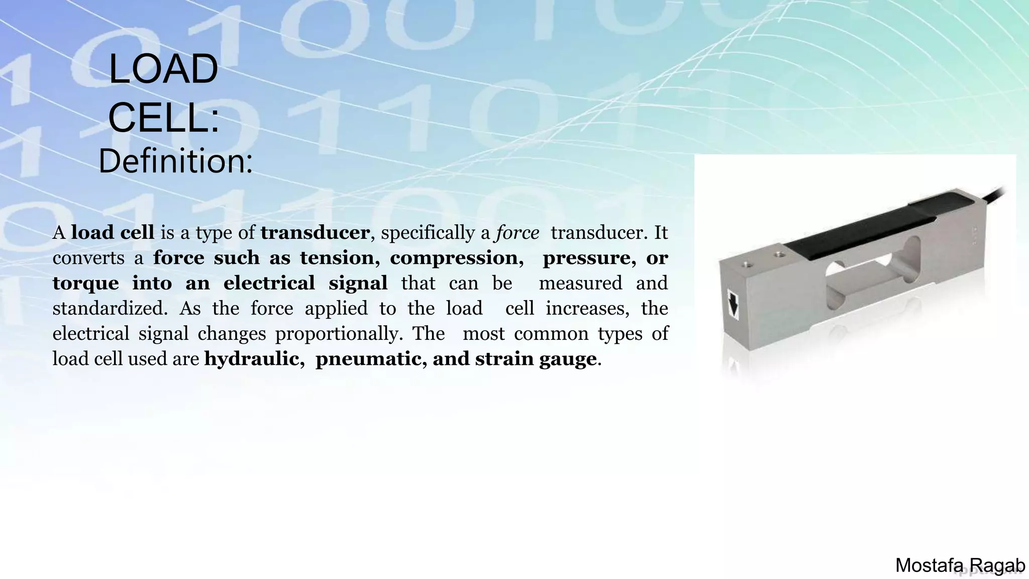
Introduction to Load Cells and their significance as force transducers.
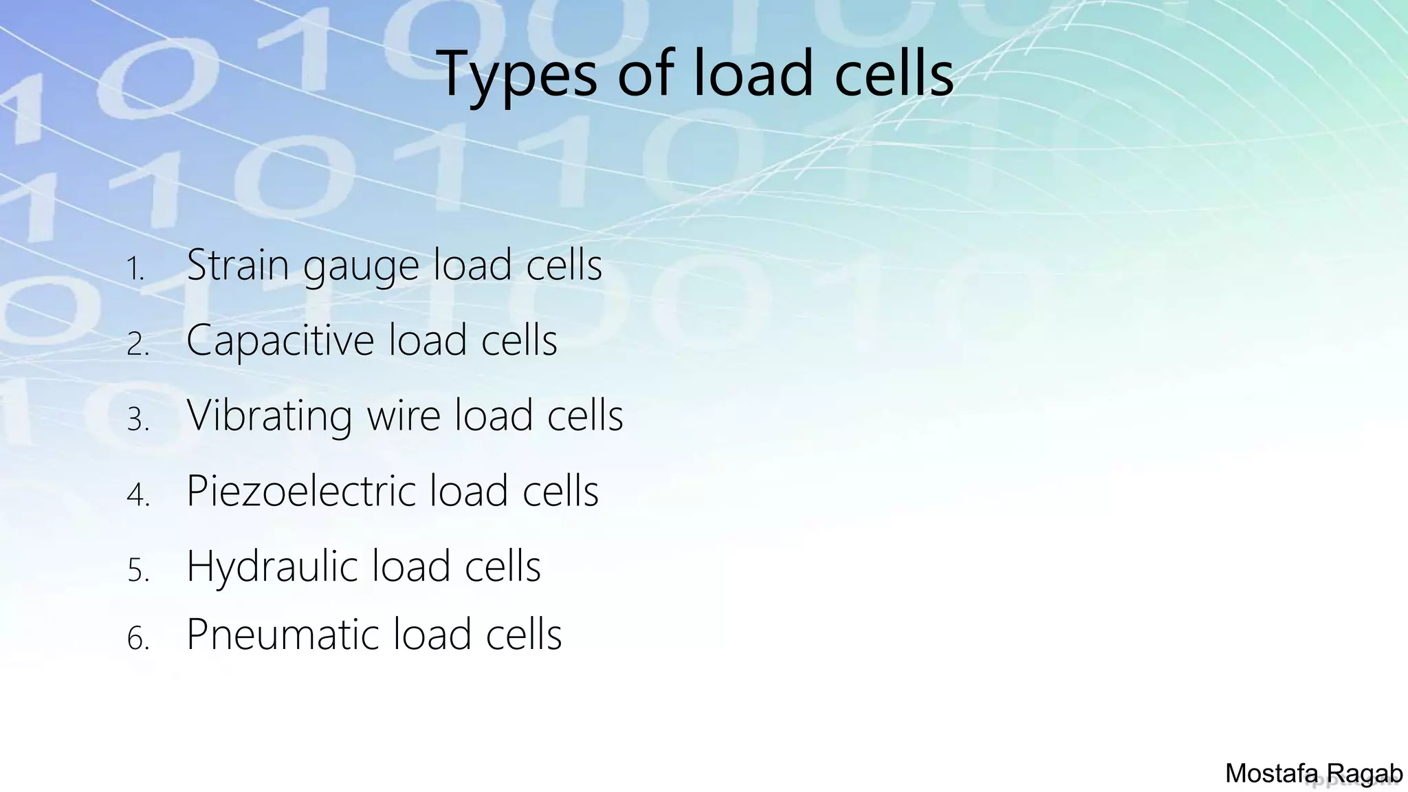
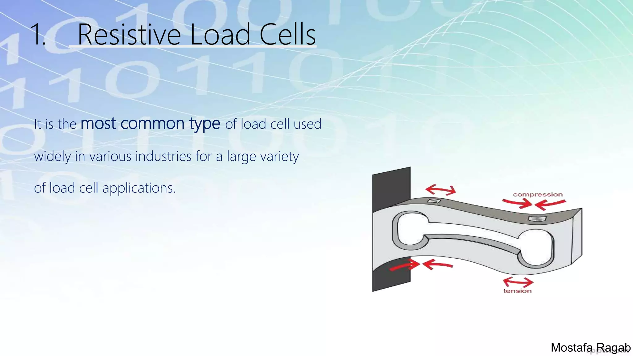
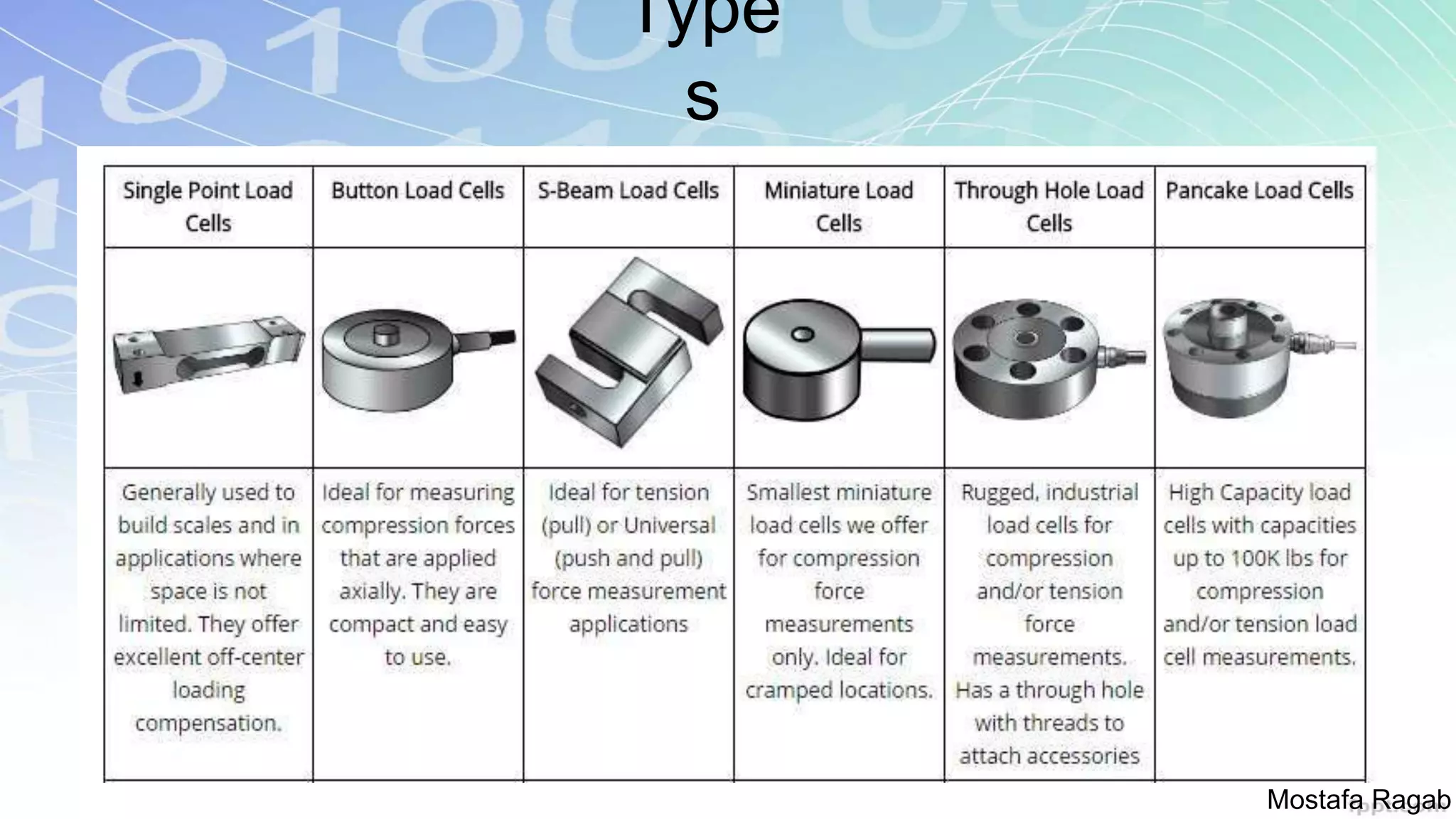
Overview of six types of load cells including strain gauge and resistive load cells.
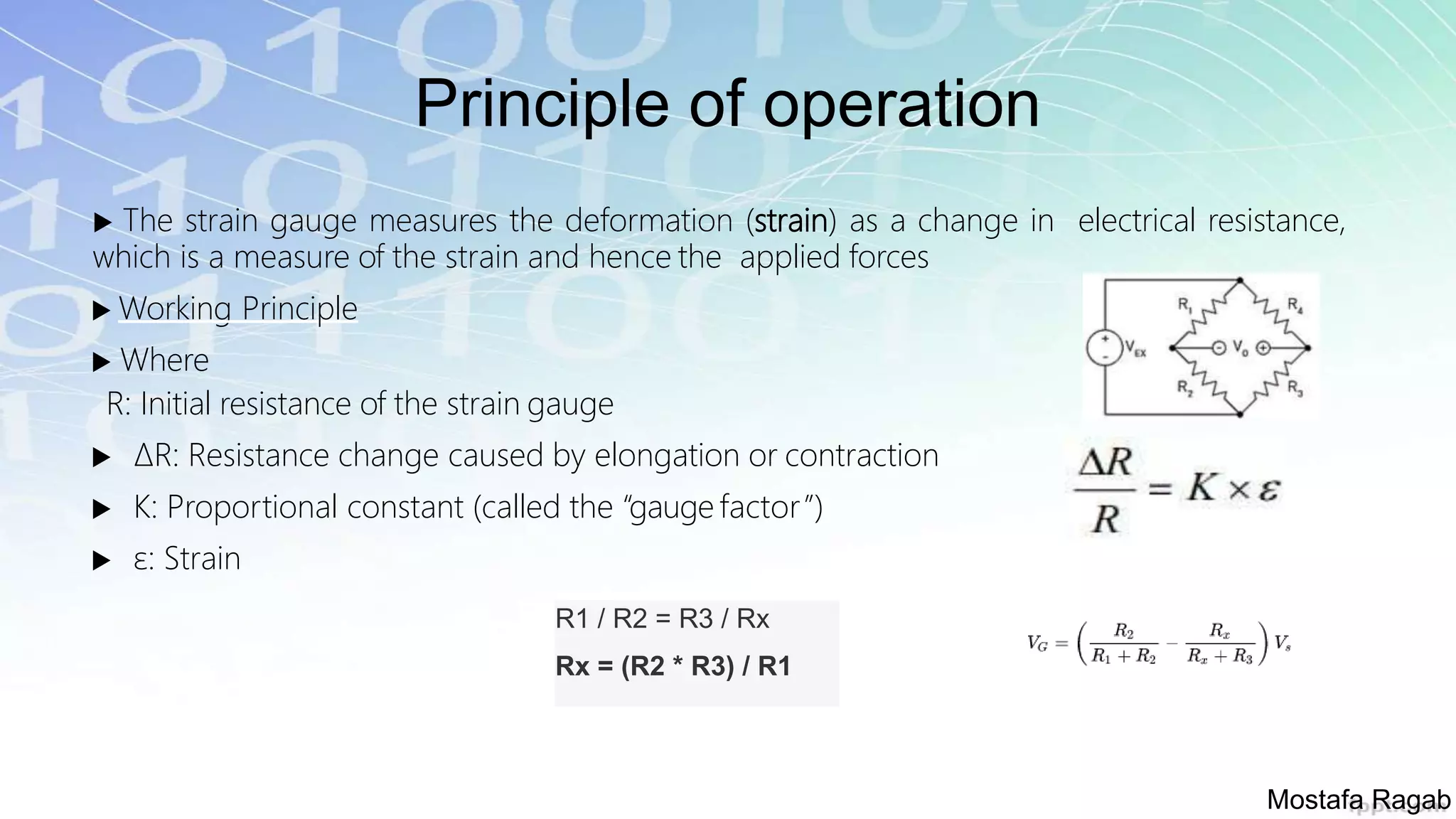
Explanation of operational principles of strain gauge load cells and their mechanics.
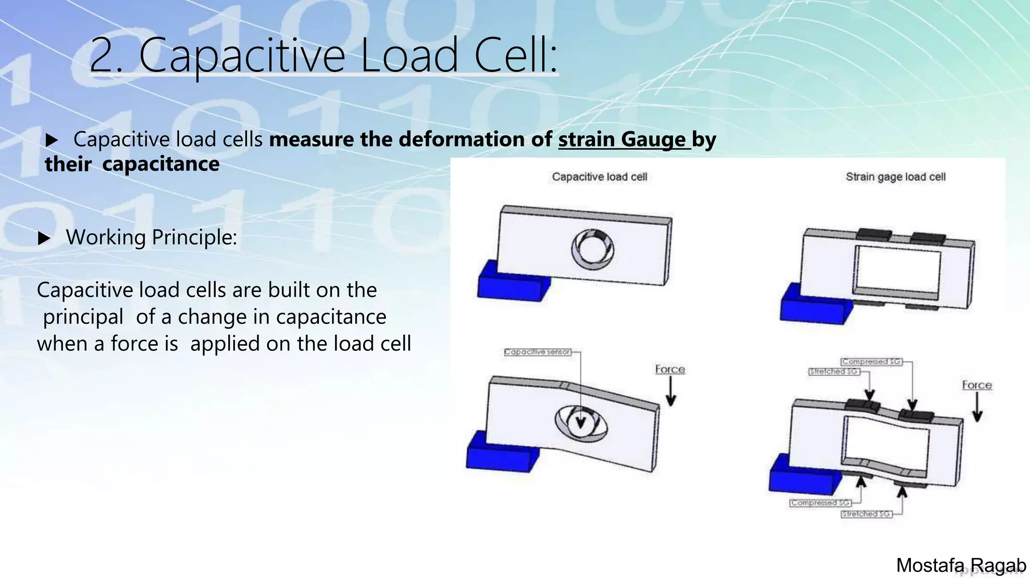
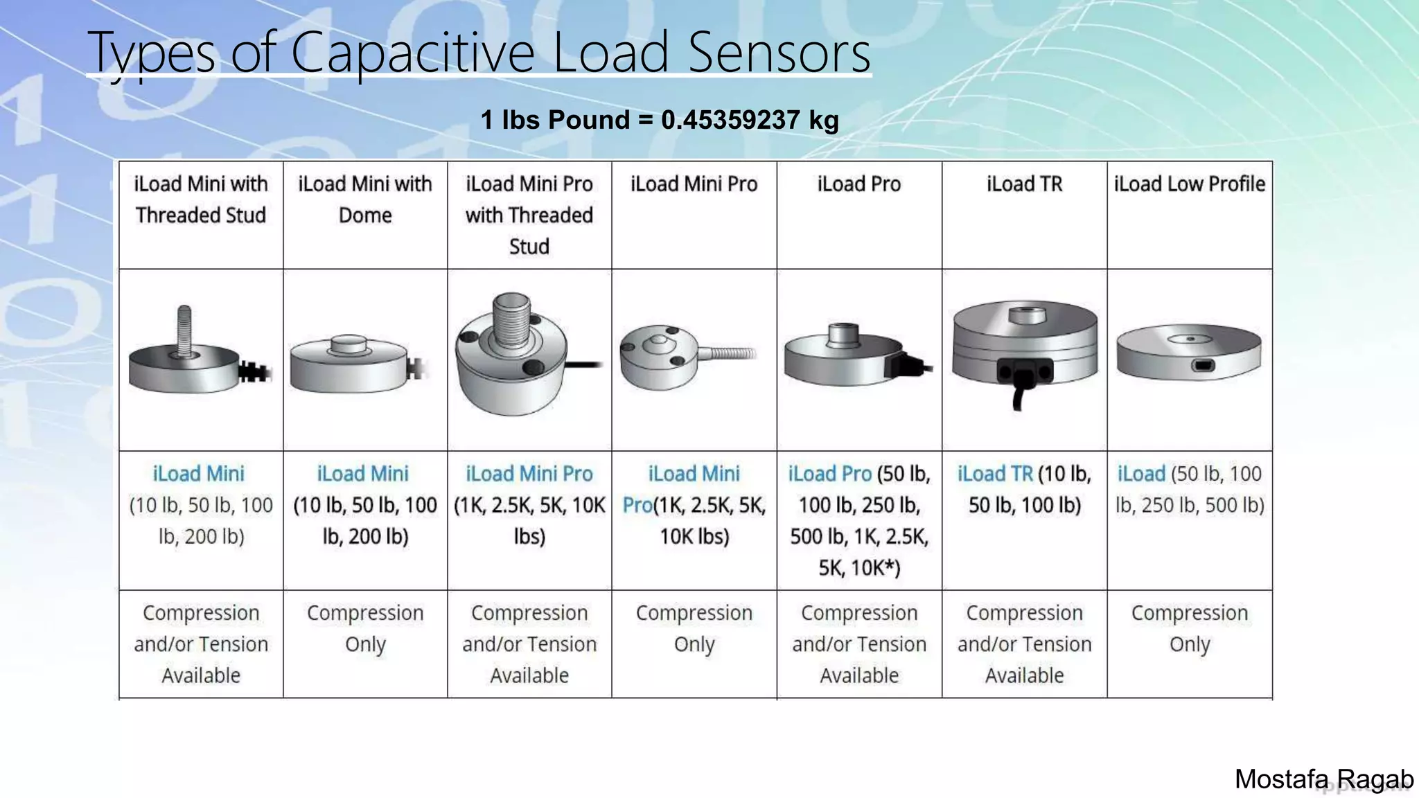
Description of capacitive load cells and the principle of operation based on capacitance changes.
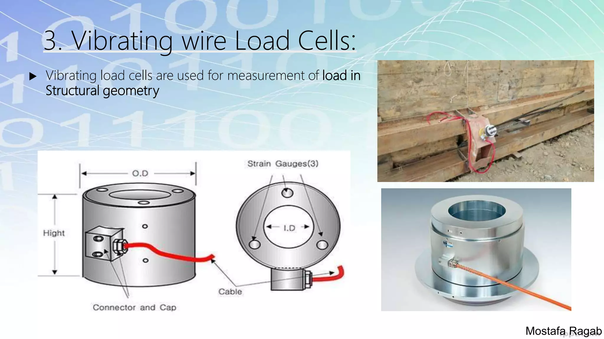
Details on vibrating wire load cells, their advantages, limitations, and usage in structural measurements.
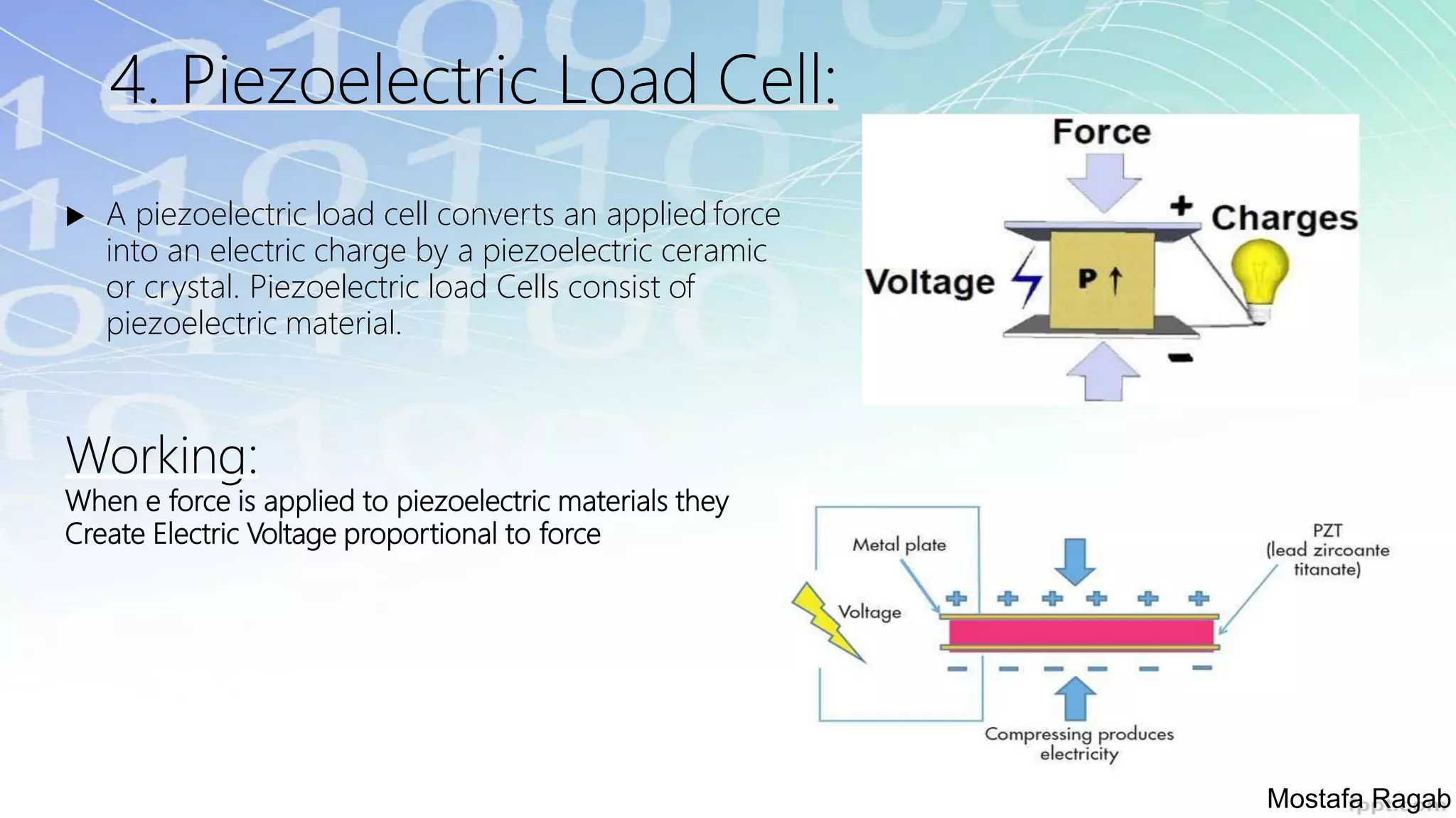
Characteristics of piezoelectric load cells, including advantages like high frequency response.
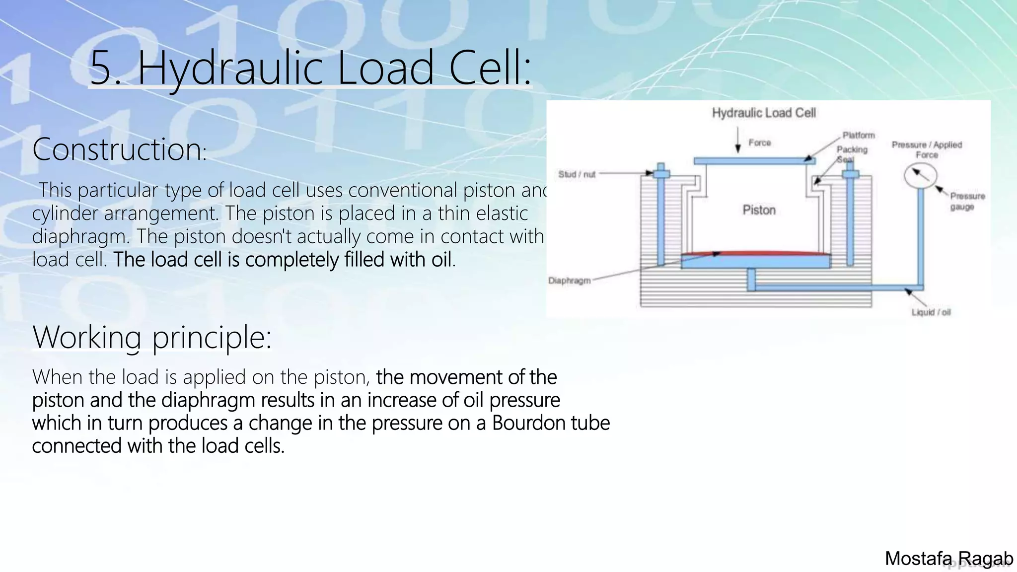
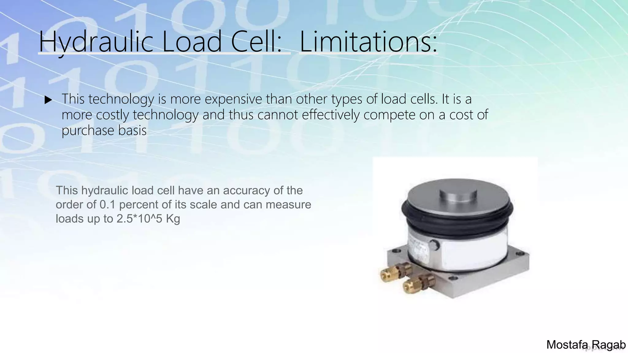
Construction and working principles of hydraulic load cells, including accuracy specifications.
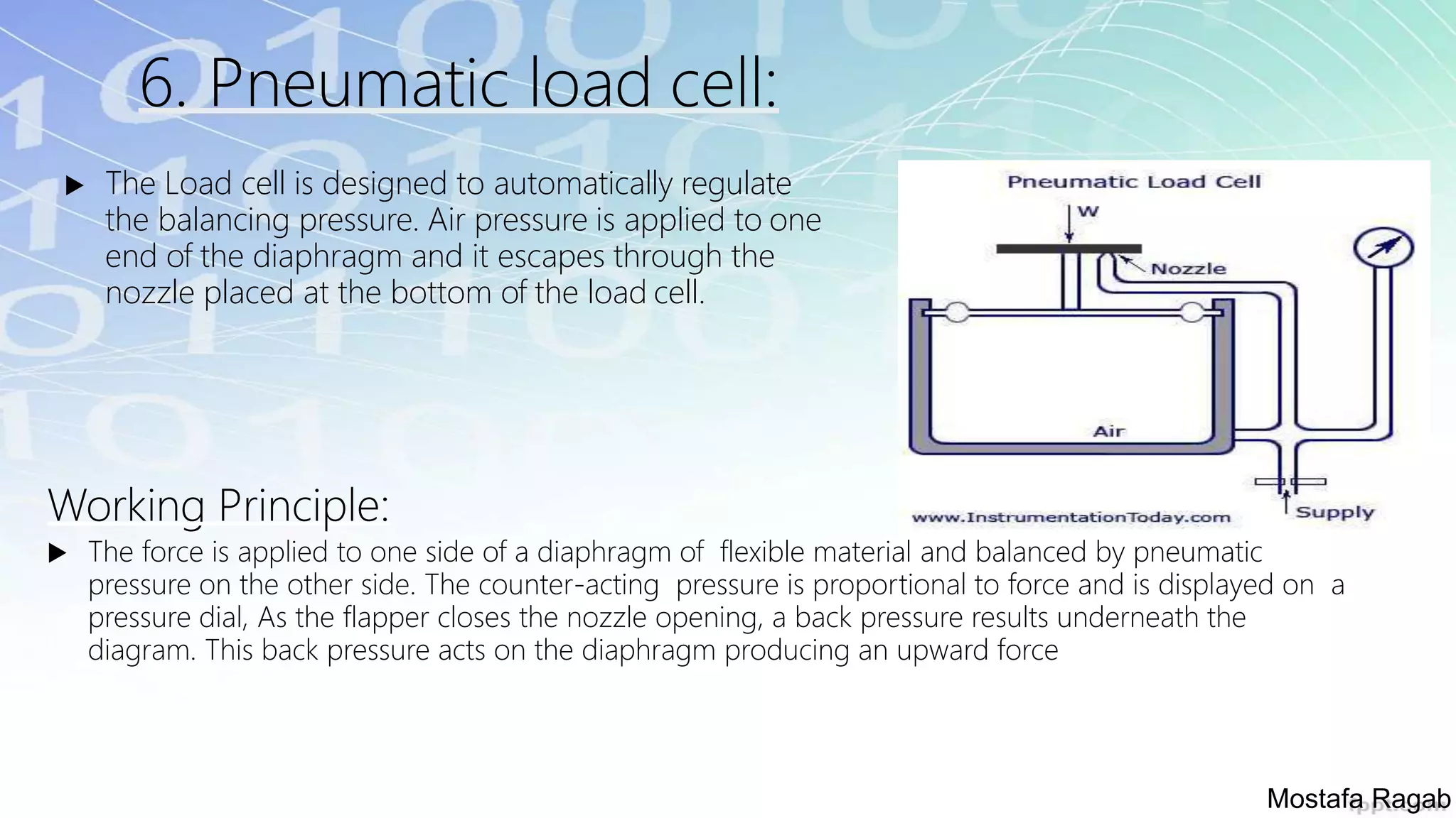
Functionality of pneumatic load cells, their advantages like explosion-proof design and limitations.
Key specifications including excitation requirements, output ratings, and signal characteristics.
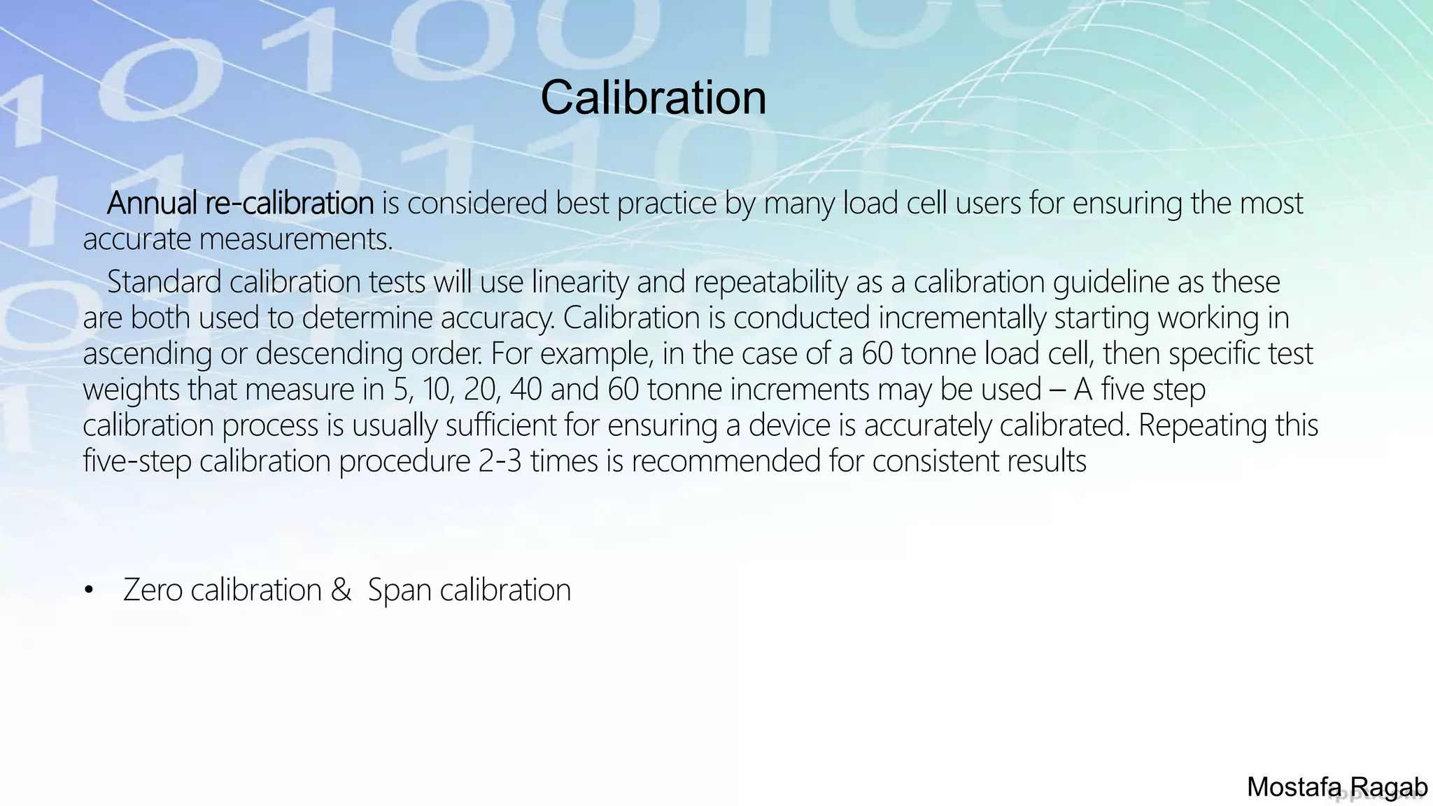
Importance of annual calibration and methods to ensure load cell accuracy.
End of presentation, summarizing the discussion on load cells.


