This document provides guidelines for designing columns, including three important thumb rules: 1) The size of columns should be no less than 9"x9" for a single story structure and larger for taller structures; 2) The distance between columns should not exceed 4m for 9"x9" columns and larger columns are needed for greater distances; 3) Columns should be aligned in straight lines or a grid to avoid structural issues. It emphasizes the importance of following these rules to prevent disastrous mistakes by engineers that could compromise safety and cost lives.


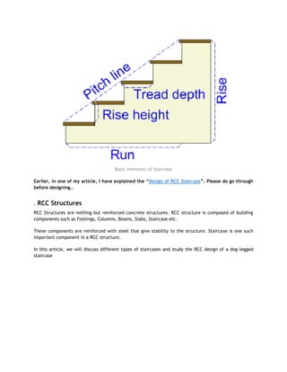
![RCC design of a Dog-legged staircase
In this type of staircase, the succeeding flights rise in opposite directions. The two flights in plan are
not separated by a well. A landing is provided corresponding to the level at which the direction of the
flight changes.
Design of Dog-legged Stairs
Based on the direction along which a stair slab span, the stairs maybe classified into the following two
types.
1. Stairs spanning horizontally
2. Stairs spanning vertically
Stairs spanning horizontally
These stairs are supported at each side by walls. Stringer beams or at one side by wall or at the other
side by a beam.
Loads
Dead load of a step = ½ x T x R x 25
Dead load of waist slab = b x t x 25
Live load = LL (KN/m2
)
Floor finish = assume 0.5 KN/m
Stairs spanning Longitudinally
In this, stairs spanning longitudinally, the beam is supported ay top and at the bottom of flights.
Loads
Self weight of a step = 1 x R/2 x 25
Self weight of waist slab = 1 x t x 25
Self weight of plan = 1 x t x 25[(R2
+ T2
)/T]
Live load = LL (KN/m2
)
Floor finish = assume 0.5 KN/m
For the efficient design of an RCC stair, we have to first analyse the various loads that are going to be
imposed on the stair.
The load calculations will help us determine, how much strength is required to carry the load. The
strength bearing capacity of a staircase is determined on the amount of steel and concrete used.
The ratio of steel to concrete has to be as per standards. Steel in the staircase will take the tension
imposed on it and the concrete takes up the compression.
These are the essential steps that are to be followed for the RCC Stair Design.](https://image.slidesharecdn.com/civil-engineering-thumb-rule-200215010306/85/Civil-engineering-thumb-rule-8-320.jpg)

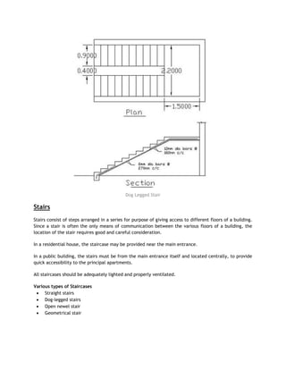
![Besides, this doubly reinforced beam is also used in the following
circumstances:
The external live loads may alternate i.e. may occur on either face of the member.
For example:
A pile may be lifted in such a manner that the tension and compression zones may alternate.
The loading may be eccentric and the eccentricity of the load may change from one side of the
axis to another side.
The member may be subjected to a shock or impact or accidental lateral thrust.
Design procedure for doubly reinforced beam
Step 1
Determine the limiting moment of resistance for the given c/s(Mulim) using the equation for singly
reinforced beam
Mulim = 0.87.fy.Ast1.d [1 – 0.42Xumax]
Or
Balanced section
Ast1 = (0.36.fck.b.Xumax)/(0.87fy)
Step 2
If factored moment Mu > Mulim, then doubly reinforced beam is required to be designed for additional
moment.
Mu – Mulim = fsc.Asc (d – d‘) [fsc value from page no. 70]
Step 3
Additional area of tension steel Ast2
Ast2 =Asc.fsc/0.87fy
Step 4
Total tension steel Ast, Ast = Ast1 + Ast2
Reinforced Cement Concrete Slab
A Reinforced Concrete Slab is the one of the most important component in a building. It is a
structural element of modern buildings. Slabs are supported onColumns and Beams.
RCC Slabs whose thickness ranges from 10 to 50 centimetres are most often used for the
construction of floors and ceilings.
Thin concrete slabs are also used for exterior paving purpose.
In many domestic and industrial buildings a thick concrete slab, supported on foundations or
directly on the sub soil, is used to construct the ground floor of a building.
In high rises buildings and skyscrapers, thinner, pre-cast concrete slabs are slung between the
steel frames to form the floors and ceilings on each level.
While making structural drawings of the reinforced concrete slab, the slabs are abbreviated to
―r.c.slab‖ or simply ―r.c.‖.](https://image.slidesharecdn.com/civil-engineering-thumb-rule-200215010306/85/Civil-engineering-thumb-rule-15-320.jpg)
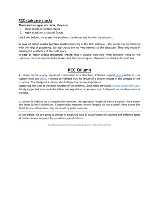
![Area required for footing
Square = B = (w+w1)/P0
Where, Po = safe bearing capacity of soil
w1 = self weight of footing
w = self weight of footing
For Rectangle = b/d = B/D
A = b x d
Net upward pressure on the footing
q/p = W/A
Step 2
Bending Moment
Critical section for maximum bending moment is taken at the face of the column
For a square footing,
Mxx = q x B/8 (L – a)2
Mxx = q x L/8 (B – b)2
Myy = q x B/8 (L – a)2
Step 3
To fix the depth of the footing shall be greater of the following:
Depth from bending moment consideration
d =?(M/Qb)
where, Q = moment of required factor
Depth from shear consideration
Check for one way shear
Check for two way shear or punching shear
Critical shear for one way shear is considered at a distance ‗d‘ from face of the column.
Shear force, V = qB [ ½(B – b) d]
Nominal shear stress, Tv = k . Tc
Tc = 0.16?fck](https://image.slidesharecdn.com/civil-engineering-thumb-rule-200215010306/85/Civil-engineering-thumb-rule-20-320.jpg)
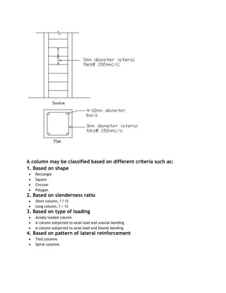
![Step 4
Check for two way shear
Critical section for two way shear is considered at a distance at a distance d/2 from all the faces of the
column.
SF, V = q [ B2
– (b + d)2
]
SF, V = q [L x B – (a + d)(b + d)]
Nominal shear stress, Tv = V/2((a+d)(b+d)d) ——- {for a rectangle
Tv = V/4((b+d)d) ——- {for a square
Tv = k . Tc
k = 0.5 + ? > 1 ; [? = ratio of sides of the column
Tc = 0.16?fck
Area of steel, Ast = M/(?stjd)
Property Valuation System
Studying Building Estimation and Costing helps us evaluate the value of the property according to its
current market trends. The Value of a property is listed into various different categories such as;
1. Market Value
2. Book Value
3. Capital Cost
4. Capitalized Value
In this article, we are going to discuss different categories under which a property is evaluated
that is Valuation is done.
Market Value
The market value of a property is the amount which can be obtained at any particular time from the
open market if the property is put for sale. The market value will differ from time to time according to
demand and supply.
The market value also changes from time to time for various miscellaneous reasons such as changes in
industry, changes in fashions, means of transport, cost of materials and labour etc.
Book Value
Book value is the amount shown in the account book after allowing necessary depreciations. The book
value of a property at a particular year is the original cost minus the amount of depreciation allowed
per year and will be gradually reduced year to year and at the end of the utility period of the property,
the book value will be only scrap value.](https://image.slidesharecdn.com/civil-engineering-thumb-rule-200215010306/85/Civil-engineering-thumb-rule-21-320.jpg)


![[Deck] What's New in Spark-Iceberg Integration via DSV2.pptx](https://cdn.slidesharecdn.com/ss_thumbnails/deckwhatsnewinspark-icebergintegrationviadsv2-260210005337-25955b12-thumbnail.jpg?width=640&height=640&fit=bounds)


