Downloaded 687 times


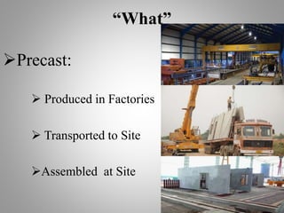


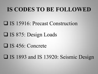


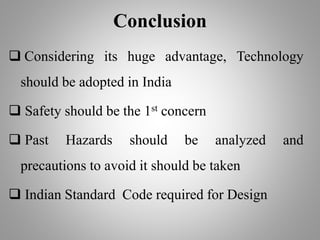


The document provides an in-depth analysis of precast construction, discussing its advantages such as material savings, construction speed, and durability. It highlights various design requirements and Indian standards that must be followed, including guidelines to prevent progressive collapse. The conclusion emphasizes the need for adopting this technology in India with a focus on safety and thorough analysis of past hazards.


