Download to read offline

![8
(6) IS 875 (PART -5)1987
(7) IS 1893(PART-1):2000
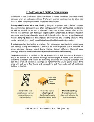
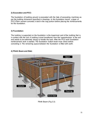
TYPES OF LOADS:
(1) DEAD LOAD [DL]
The dead load includes loads that are relatively constant over time, including
the weight of the structure itself, and immovable fixtures such as
walls, plaster or carpet.
The roof is also a dead load.
Dead loads are also known as permanent or static loads.
Building materials are not dead loads until constructed in permanent position.
(2) LIVE LOAD [LL]
Live loads, or imposed loads, are temporary, of short duration, or a moving load.
o These dynamic loads may involve considerations such as impact, momentum,
vibration, slosh dynamics of fluids and material fatigue.
o Roof and floor live loads are produced during maintenance by workers,
equipment and materials, and during the life of the structure by movable objects,
such as planters and people.
o Bridge live loads are produced by vehicles traveling over the deck of the bridge.
(3) WIND LOAD [WL]
o The term ‘Wind Load’ is used to refer to any pressures or forces that the wind
exerts on a building or structure
(4) EARTHQUAKE LOAD [EL]
Earthquake load takes place due to the inertia force produced in the building
because of seismic excitations. Inertia force is varies with the mass.
The higher mass of the structure will imply that the earthquake loading will also
be high.
LIVE LOAD IS THE ONE FOR WHICH WE ARE GOING TO DESIGN.](https://image.slidesharecdn.com/d18cl124internshipreport-210422062701/85/D18cl124-internship_report-12-320.jpg)
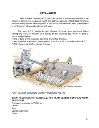
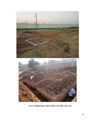
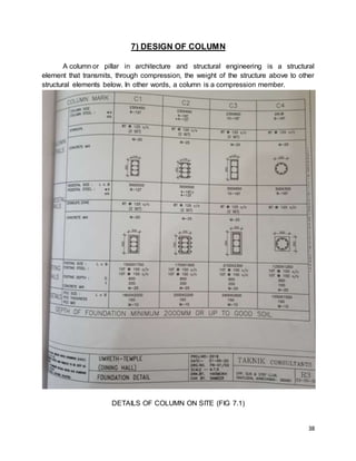
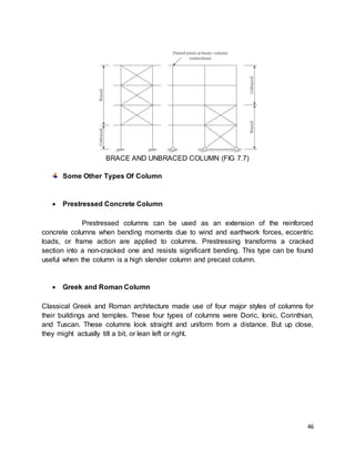
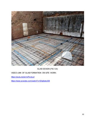
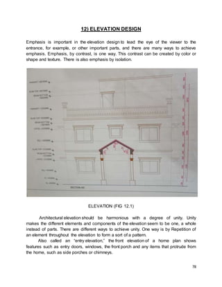

The document discusses the analysis and design of a residential building project submitted by Patel Dhruv Jitendrabhai for their Bachelor of Technology degree. It includes details of the construction process from excavation and foundation work to slab work and services. The report covers the design of key structural elements like beams, columns, slab, and staircase according to Indian standard codes.


