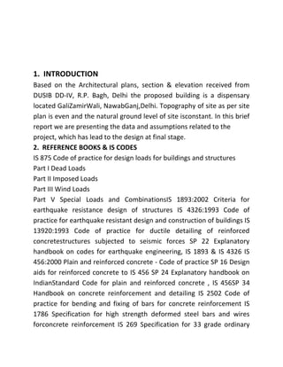
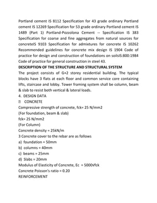
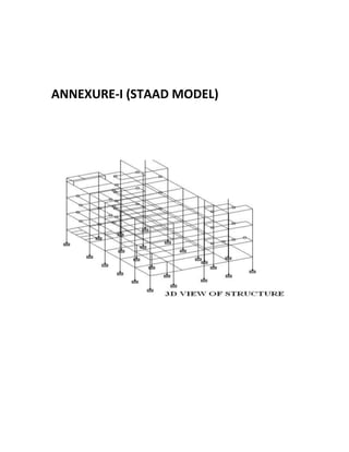
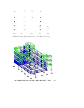
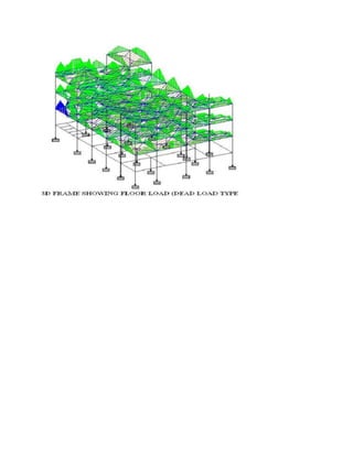
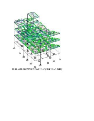
The document provides details about the design of a G+2 residential building structure located in Delhi for Swati Structure Solutions Pvt. Ltd. It includes information on the design loads as per Indian codes, analysis of the structure using STAAD Pro software, load calculations, seismic design criteria as per IS 1893, and design and detailing of reinforced concrete structural elements. The structure will consist of a column-beam-slab framing system to resist vertical and lateral loads.
Design of multi storey building resting on single columneSAT Journals
Abstract The aim of the project is to analyze and design of multi-storey building resting on the single column by using different code
provisions. A lay out plan of the proposed building is drawn by using AUTO CADD 2010.The structure consist of ground floor
plus five floors, each floor having the one house .Staircase must be provides separately. The planning is done as per Indian
standard code provisions. The building frames are analyzed using the various text books. Using this so many standard books
analysis of bending moment, shear force, deflection, end moments and foundation reactions are calculated. Detailed structural
drawings for critical and typical R.C.C. members are also drawn. Co-ordinates for all structural members are tabulated for ready
reference.
Keywords: Multi Story Building, Single Column, Staircase.
Design and analysis of reinforced concrete multistory commercial building usi...Estisharaat Company
Design of multistory building by solving a sample manually ans rest of the building by solving on autodesk robot analysis, complete detailing of r.c members,final year project,complete ,how to design slabs, how to design beams, how to design rc column, how to make final year project, design of stairs,how to design foundations , how to prepare a project before using it in software for analysis,
Construction stage analysis of rcc frames project reportSayyad Wajed Ali
While analyzing a multistorey building frame, conventionally all the probable loads are applied after modeling the entire building frame. But in practice the frame is constructed in various stages. Accordingly, the stability of frame varies at every construction stage. Even during construction freshly placed concrete floor is supported by previously cast floor by formwork. Thus, the loads assumed in conventional analysis will vary in transient situation. Obviously, results obtained by the traditional analysis will be unsuitable. Therefore, the frame should be analyzed at every construction stage taking into account variation in loads. The phenomenon known as Construction Stage Analysis considers these uncertainties precisely. This paper analyzes several numbers of multistorey reinforced concrete building frames of different bay width and length, storey height and number of stories using STAADpro, followed by the construction stage analysis of each model. Also all full frame models are analyzed for earthquake forces in Zone - II (IS 1893 : 2002). Finally, a comparative study of Axial forces, Bending moments, Shear forces and Twisting moments was done at every storey for full frame model (without earthquake forces) and construction stage model (without earthquake forces).
CADmantra Technologies Pvt. Ltd. is one of the best Cad training company in northern zone in India . which are provided many types of courses in cad field i.e AUTOCAD,SOLIDWORK,CATIA,CRE-O,Uniraphics-NX, CNC, REVIT, STAAD.Pro. And many courses
Contact: www.cadmantra.com
www.cadmantra.blogspot.com
www.cadmantra.wix.com
Analysis and design of multystory buildingAwat Hasan Ra
a presentation about analysis and design of a multy-story building as hotel using hand calculating and programas of STAAD-pro and STA4-cad, it was done by microsoft office 2013.
In the present era the technology in communications has developed to a very large extent. The communication industries have seen a tremendous increase in last few years which have resulted in installation of large number of towers to increase the coverage area and network consistency. In wireless communication network these towers play a significant role hence failure of such structure in a disaster is a major concern. Therefore utmost importance should be given in considering all possible extreme conditions for designing these towers. In most of the studies, the researches have considered the effect of wind only on the four legged self-supporting towers. In this dissertation, a four legged lattice tower is analyzed and designed along with foundation details.
2. INPLANT TRAINING REPORT
Submitted By
ANKUR KUMAR
Reg no.:-9910003003
3rd YEAR, B.TECH
In partial fulfillment
of
Bachelor of Technology
in
CIVILENGINEERING
From 6/12/2012 to 27/12/2012
KALASALINGAM UNIVERSITY
(Kalasalingam Academy of Research and Education)
Krishnankoil-626190
3. COMPANY PROFILE
Established in 1990, Swati Structure Solution Pvt. Ltd. stands for
Quality, Reliability and Trustworthiness. A
multifacetedorganization, SSPL provides an entiregamut of
solutions, be it in Architecture, Infrastructure, Engineering and
Planning.
SSSPLwholly owned Indian company. SSSPLis one of the fastest
growing infrastructure consultants in India. With offices in New
Delhi & Chandigarh and plans to develop offices in south India.
Our current areas of operations include Transport Planning,
Roads,Bridges, Rail& Buildings. Today, there are more than 45
staff employed by SSPL in Delhi & Chandigarh, including
specialists in the fields of transportation,highways, rail, bridges
and civil engineering.
Our employees have achieved several milestones, which are of
tremendous importance to them and the company.
AREA OF EXCELLENCE
Sectors
• Buildings
4. • Architecture
• Bridge, Flyover & Interchanges
• Foot over Bridge
• Rail over Bridge & Rail under Bridge
• Highway, Expressway & Village Roads
• Traffic& Transportation
Services/Studies
• Planning and feasibility studies
• Strategic option studies
• Geotechnical, Hydrological & Other Investigation
• Design, Project Preparation & Cost Estimation
5. TABLE OF CONTENTS
INTRODUCTION
REFERENCE BOOKS & IS CODES
DESCRIPTION OF THE STRUCTURE AND
STRUCTURAL SYSTEM
DESIGN DATA
ALLOWABLE DEFLECTIONS
DESIGN PHILOSOPHY
ANALYSIS, MODEL AND SOFTWARE USED
LOAD CONSIDERATION
LOAD CALCULATION
SEISMIC DESIGN CRITERIA
DESIGN & DETAILING OF RCC STRUCTURE
LOAD COMBINATIONS FOR CONCRETE DESIGN
OF STRUCTURAL ELEMENTS
NET SAFE BEARING CAPACITY
GUIDELINE NOTES
DRAWING INTERPRETATION
ANNEXURE-I (STAAD MODEL)
DESIGN OF STAIR CASE SPANNING LONGITUDINALLY
6. 1. INTRODUCTION
Based on the Architectural plans, section & elevation received from
DUSIB DD-IV, R.P. Bagh, Delhi the proposed building is a dispensary
located GaliZamirWali, NawabGanj,Delhi. Topography of site as per site
plan is even and the natural ground level of site isconstant. In this brief
report we are presenting the data and assumptions related to the
project, which has lead to the design at final stage.
2. REFERENCE BOOKS & IS CODES
IS 875 Code of practice for design loads for buildings and structures
Part I Dead Loads
Part II Imposed Loads
Part III Wind Loads
Part V Special Loads and CombinationsIS 1893:2002 Criteria for
earthquake resistance design of structures IS 4326:1993 Code of
practice for earthquake resistant design and construction of buildings IS
13920:1993 Code of practice for ductile detailing of reinforced
concretestructures subjected to seismic forces SP 22 Explanatory
handbook on codes for earthquake engineering, IS 1893 & IS 4326 IS
456:2000 Plain and reinforced concrete - Code of practice SP 16 Design
aids for reinforced concrete to IS 456 SP 24 Explanatory handbook on
IndianStandard Code for plain and reinforced concrete , IS 456SP 34
Handbook on concrete reinforcement and detailing IS 2502 Code of
practice for bending and fixing of bars for concrete reinforcement IS
1786 Specification for high strength deformed steel bars and wires
forconcrete reinforcement IS 269 Specification for 33 grade ordinary
7. Portland cement IS 8112 Specification for 43 grade ordinary Portland
cement IS 12269 Specification for 53 grade ordinary Portland cement IS
1489 (Part 1) Portland-Pozzolona Cement -- Specification IS 383
Specification for coarse and fine aggregates from natural sources for
concreteIS 9103 Specification for admixtures for concrete IS 10262
Recommended guidelines for concrete mix design IS 1904 Code of
practice for design and construction of foundations on soilsIS:800:1984
Code of practice for general construction in steel 43.
DESCRIPTION OF THE STRUCTURE AND STRUCTURAL SYSTEM
The project consists of G+2 storey residential building. The typical
blocks have 3 flats at each floor and common service core containing
lifts, staircase and lobby. Tower framing system shall be column, beam
& slab to resist both vertical & lateral loads.
4. DESIGN DATA
CONCRETE
Compressive strength of concrete, fck= 25 N/mm2
(For foundation, beam & slab)
fck= 25 N/mm2
(For Column)
Concrete density = 25kN/m
3 Concrete cover to the rebar are as follows
a) foundation = 50mm
b) columns = 40mm
c) beams = 25mm
d) Slabs = 20mm
Modulus of Elasticity of Concrete, Ec = 5000√fck
Concrete Poisson's ratio = 0.20
REINFORCEMENT
8. Reinforced steel yield strength, fy = 500N/mm2
Modulus of elasticity ofsteel, Es = 2.05X10⁸kN/mm2
5. ALLOWABLE DEFLECTIONS
a) The final deflection due to dead loads and live loads (unfactored)
measured fromas cast levels of supports is not more than Span/250.
b) The deflection after erection of partitions and the application of
finishes is not morethan span/350 or 20 mm, whichever is the lesser
Lateral Frame Deflection (StoryDrift) Under Seismic Load:
Story Drift under nominal seismic loads is not more than 0.004h, where
h is the story Height. Maximum value of story drift will be given after
analysis.
6. DESIGN PHILOSOPHY
a) Building has been analyzed for conventional loads, Structural
members/ componentincluding foundation, RCC slab, beams and
columns are designed for the dead, live & seismic loads. The beams and
columns frame arrangement and design has been done by using STAAD
PRO version V8i.
b) All the RCC columns of the building are supported on Raft
foundation. Foundation are typically designed for the reaction obtained
from predominant load case, byanalyzing on STAAD PRO
c) Serviceability & strength checks of foundation & members are
carried out as per IS 456: 2000 5
7. ANALYSIS, MODEL AND SOFTWARE USED
i) Super Structure: - The building has been analysed as a 3-dimensional
skeletal structure of beam column frame structure using STAAD PRO
version V8i software.
ii) Sub Structure: -STAAD PRO V8i adopted for the analysis & design of
foundation.
9. 8. LOAD CONSIDERATION
Dead Loads includes self weight of structure is taken as per IS 875 (Part-
1) - 1987 Imposed Loads is taken as per IS 875 (Part-2) - 1987
Earthquake loads are calculatedas per IS 1893 (Part 1) : 2002 Load
combinations shall be taken as per IS 1893 (2002) & IS 875 (Part-5) -
1987
9. LOAD CALCULATION
9.1 Dead Load
a) Self Weight = Automatically calculated by software
b) Brick wall load
i) 230mm Thk. Wall = 5kN/m Run/m height
Floor to floor height = 3.30m(Net Height) = 3.00-0.45 = 2.85m
Weight of Wall = 2.85 x 5.0 = 14.25 kN/m
ii) 115mm Thk. Wall = 2.75kN/m Run/m height
Floor to floor height = 3.30m(Net Height) = 3.00-0.45 = 2.85m
Weight of Wall = 2.85 x 2.75 = 7.838 kN/m
Say 7.85kN/m
iii) Parapet Wall 230mm Thk. (1.0m High)
Weight of Wall = 1.0 x 5.0 = 5 kN/m
c) Floor Load
i) Typical Floor
Self Weight of Slab = 0.125 x 25 = 3.125kN/sqm
(This will vary for different slab thickness)
Floor Finish = 0.05 x 24 = 1.2kN/sqm
Ceiling Plaster = 0.006 x 20 = 0.12kN/sqm
10. Total Dead Load = 4.445kN/sqm
Say = 4.50kN/sqm6
ii) Toilets
Self Weight of Slab = 0.125 x 25 = 3.125kN/sqm
Floor Finish = 0.05 x 24 = 1.2kN/sqm
Ceiling Plaster = 0.006 x 20 = 0.12kN/sqm
Sunken = 0.5 x 20 = 10.0kN/sqm
Partition = 1.0kN/sqm
Total Dead Load = 12.82kN/sqm
iii) Kitchen
Self Weight of Slab = 0.125 x 25 = 3.125kN/sqm
Floor Finish = 0.05 x 24 = 1.2kN/sqm
Ceiling Plaster = 0.006 x 20 = 0.12kN/sqm
Sunken = 0.15 x 20 = 3.0kN/sqm
Total Dead Load = 7.445kN/sqm
Say = 7.5kN/sqm
iv) TerraceLvl.
Self Weight of Slab = 0.125 x 25 = 3.125kN/sqm
(This will vary for different slab thickness)
Water proofing/Brick Coba = 0. 2 x 20 = 4.0kN/sqm
Ceiling Plaster = 0.006 x 20 = 0.12kN/sqm
Total Dead Load = 7.245kN/sqm
Say = 7.50kN/sqm
9.2 Imposed Load
a) All rooms and Kitchen = 2kN/sqm
b) Toilet and Bath Rooms = 2kN/sqm
c) Hall, Corridors, passages, lobbies, staircases
11. including fire escapes and store rooms = 4kN/sqm
d) Balconies = 3kN/sqm
10. SEISMIC DESIGN CRITERIA
Seismic loads are calculated as per provisions of IS: 1893-2002. The
parameters selected are given below Fundamental natural time period
is taken as Ta = 0.075h0.75as per clause 7.6.1 of IS: 1893-2002, for
R.C.C Frame Building. h = Height of building in meter. Parameter Value
Z i.e. Zone Factor 0.24 (For zone IV)
I i.e. Importance Factor 1.5
R i.e. Response Reduction Factor
5 h i.e. Height of Building As/arch.dwg.
Length & width of Building As/arch.dwg.
Soil Type Medium 7 Response Spectrum reduction factor is taken as
5.0 from table 7 of IS: 1893-2002 For special Reinforced Cement
Concrete Frames (Moment resisting frames specially detailed to
provide ductile behavior). The Time period of the structure has also
been worked out using software. The building has been designed for
base shear based on codal time periodin accordance with clause7.8.2 of
IS: 1893-2002 using modification factor = VB/VBwhereVBis calculated
based on codal time period Ta = 0.075h0.75 and VBis calculated based
on time period given by software. The horizontal earthquake force has
been calculated for the full dead load & Reduce liveload as per clause
7.3.1 Table-8 of IS:1893-2002.
11. DESIGN & DETAILING OF RCC STRUCTURE
The design of RCC Beam & Slab is being done using IS: 456-2000 and SP-
16. Limit state method of structure design is being followed. Columns
and beams are being designed using STAAD PRO version V8i software.
12. 12. LOAD COMBINATIONS FOR CONCRETE DESIGN OF STRUCTURAL
ELEMENTS
The limit state load combinations used for design of concrete structural
elements such as beams & columns are as per IS:875 Part 5 and IS:456.
They are listed below. Various load combinations considered are as
follows:-
1. 1.5 (D.L+ Reduced L.L) as per Fig. 1 of IS: 875 – 1987 (Part-2)
2. 1.5 (D.L E.Q in Xdirection)
-
3. 1.5 (D.L E.Q in -direction)
Z
4. 1.2 (D.L + K1L.L E.Q in Xdirection)
-
5. 1.2 (D.L + K1L.L E.Q in -direction)
Z
6. 0.9 (D.L) + 1.5 E.Q. in X-direction
7. 0.9 (D.L) + 1.5 E.Q. in Z-direction
D.L =Dead loads
L.L = Live loads
E.Q= Earthquake loads
K1= 0.25 For live load class upto 300Kg/m2, 0.5 For live load class above
300Kg/m2
However unfactored loads are used for size& pressure calculations of
foundation.
13. NET SAFE BEARING CAPACITY
Geotechnical reportFoundation design shall be based on the
geotechnical investigation report. The net safe bearing capacity of soil
is 13t/sqm at 3.0m depth from N.G.L.
14. GUIDELINE NOTES
13. Guideline Notes for Concrete Work are available in General Detail
Drawings and Notesof Swati Structure Solution Pvt. Ltd. and shall be
supplied along with working drawings. Reinforcing steel
specificationReinforcing steel to be used in this project is Fe500 grade
T.M.T. bars corresponding to 0.2% proof stress The reinforcing steel
should have a minimum elongation of 14.5%. Details and notes on
reinforcement are available in General Detail Drawings and Notes of
Swati structure solution pvt.ltd. The following are included in the notes:
1. Notes on reinforcement
2. Development length and lap length of reinforcement based on grade
of steel
and grade of concrete
3. Cover to reinforcement
4. Details of bends and hooks etc.
15. DRAWING INTERPRETATION
Abbreviations, definitions, symbols and notationsAbbreviations,
definitions, symbols and notations used in the structural drawings are
obtained in the General Detail Drawings and Notes of Swati Structure
solution pvt.ltd Typical details Typical details of various elements can
be obtained in the General Detail Drawings and Notes of Swati
structure solution pvt.ltd. In cases where specific details are not
included in the structural drawings, reference shall be made to these
details by the contractor. No construction work shall proceed on site
without studying these General Detail Drawings and Notes