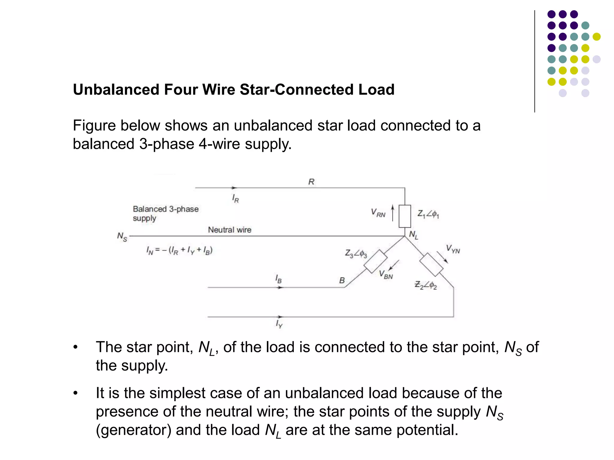
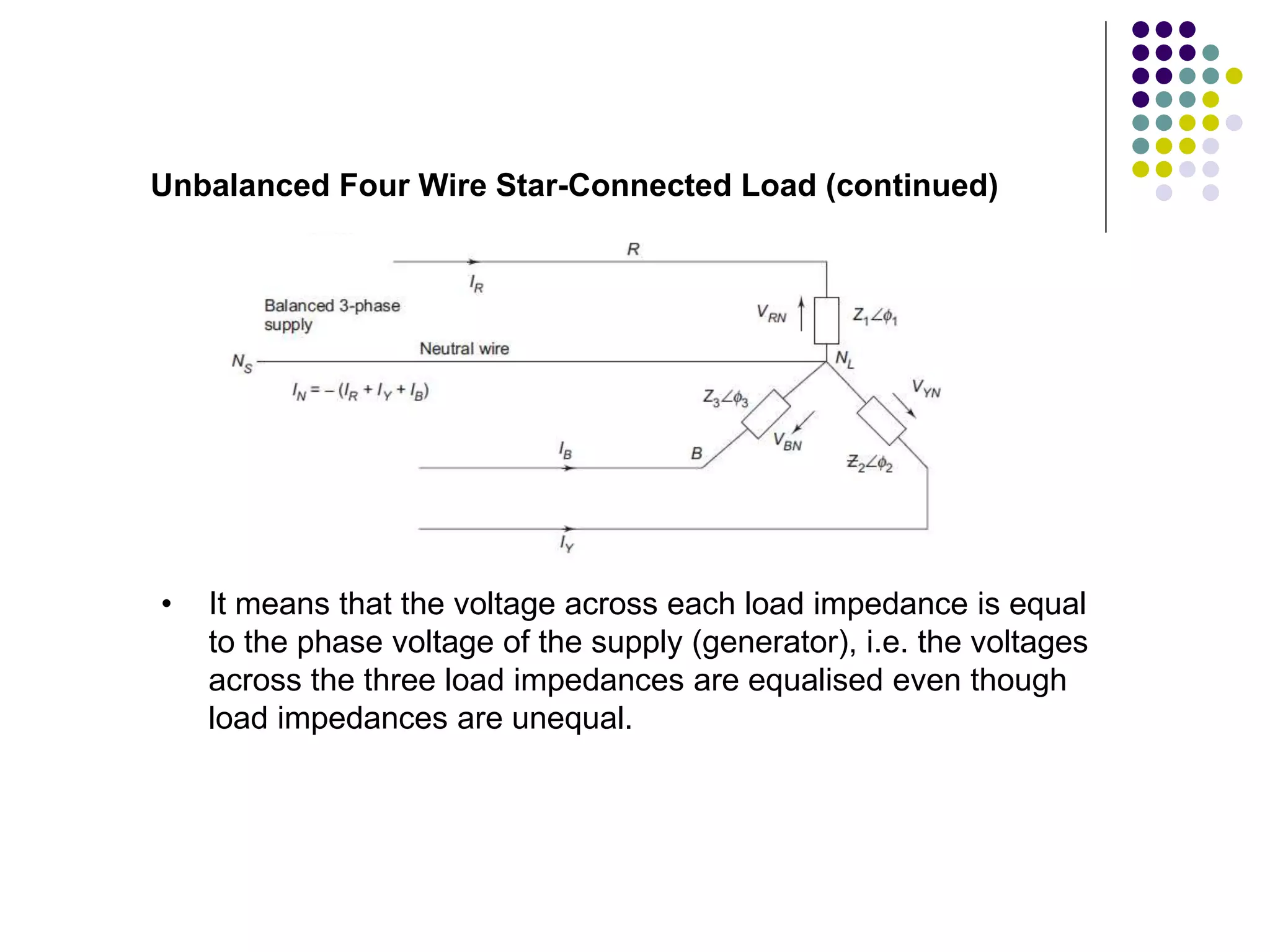
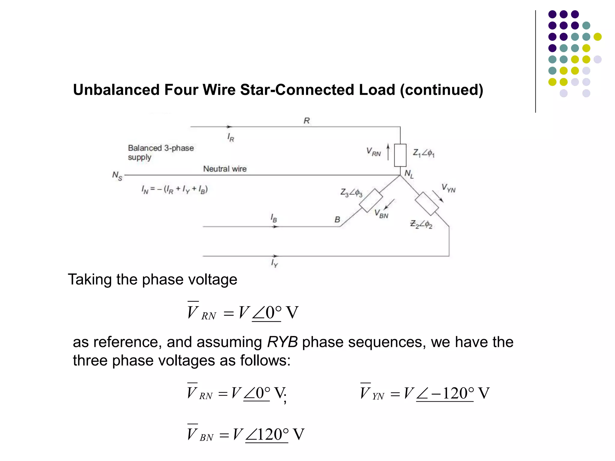
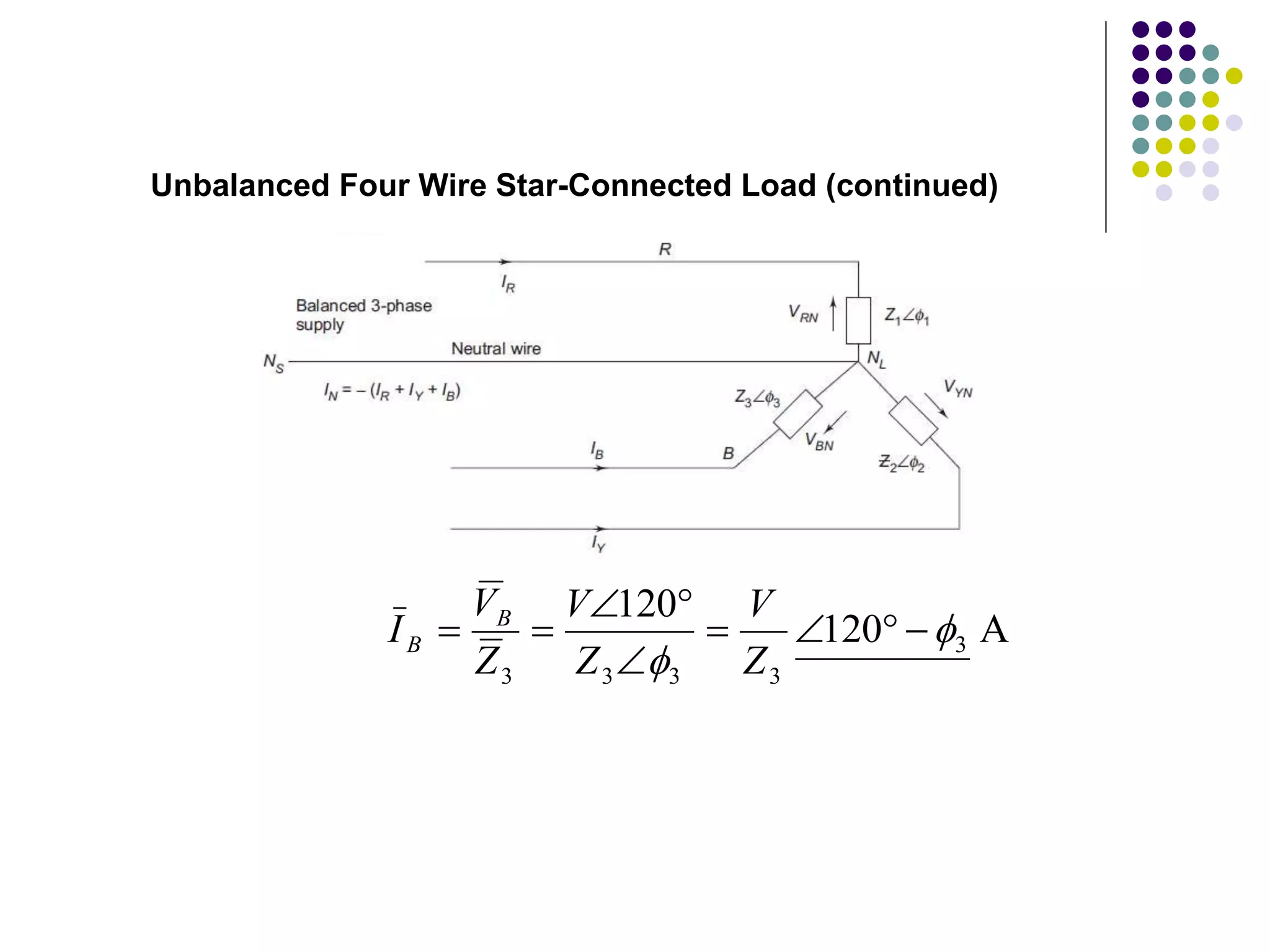
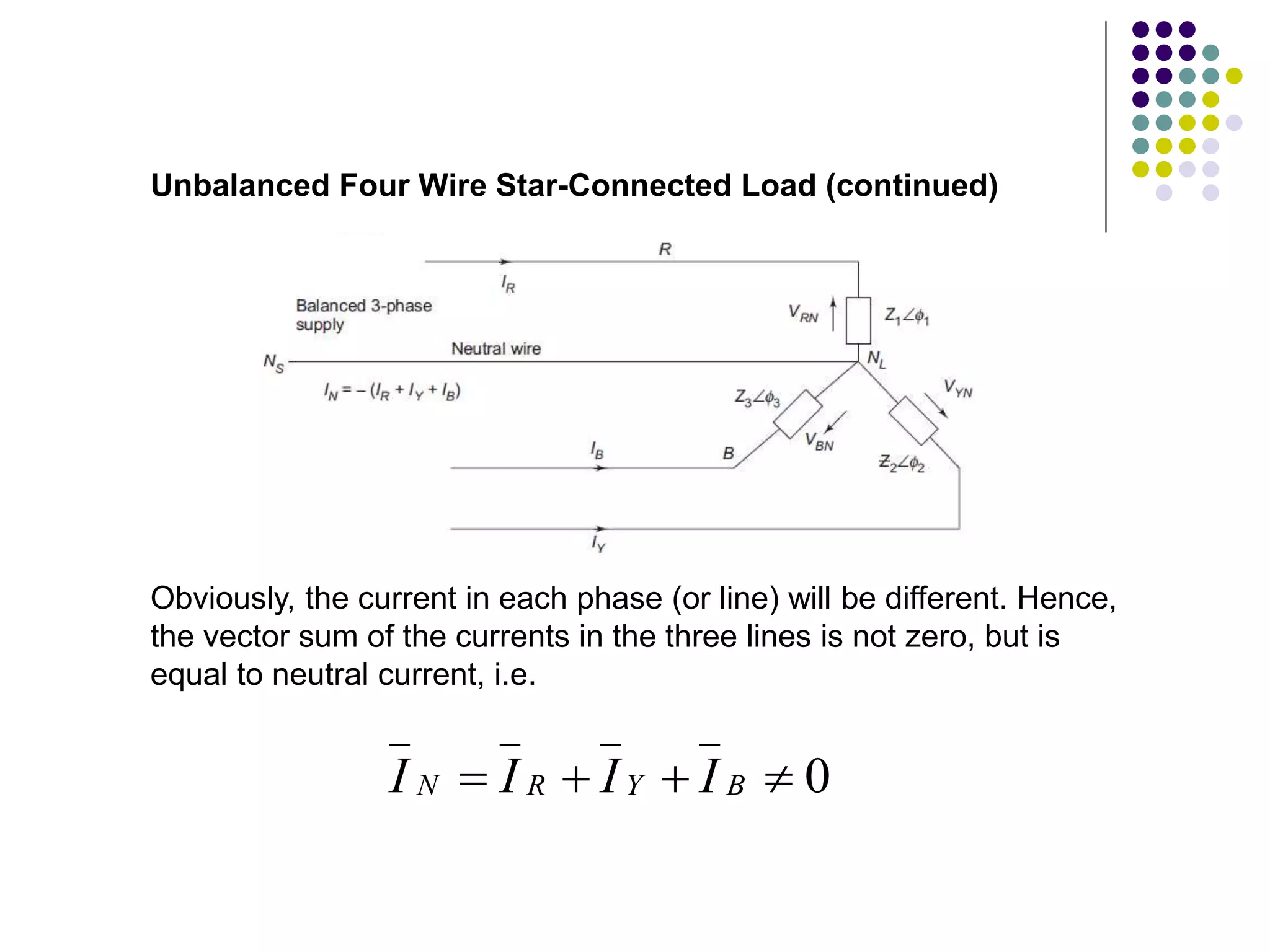
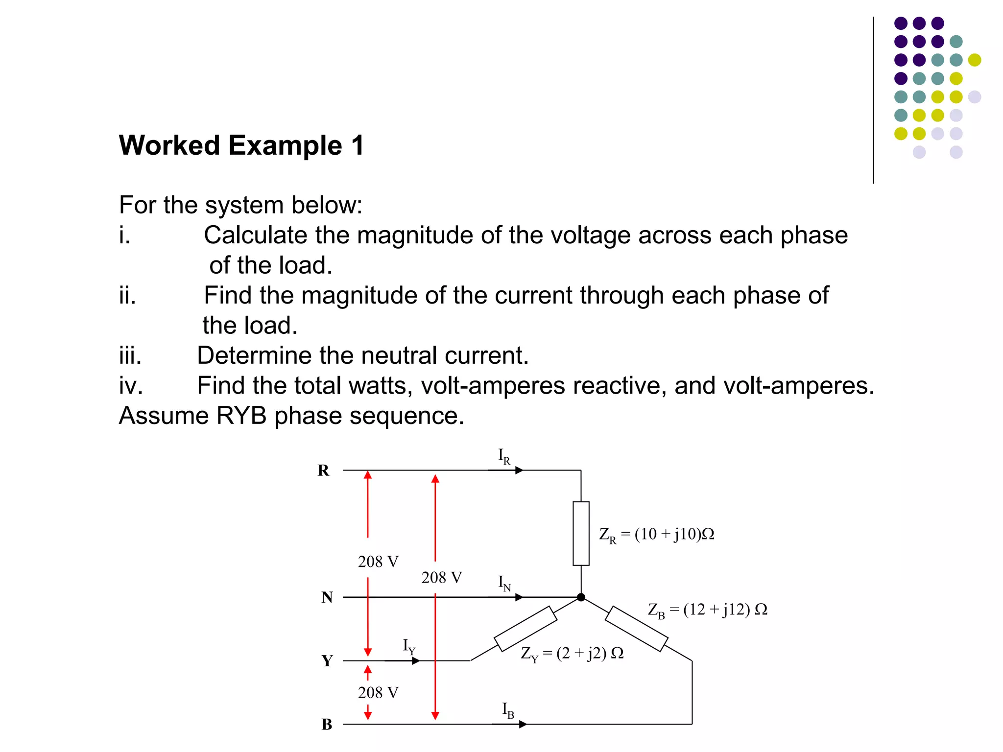
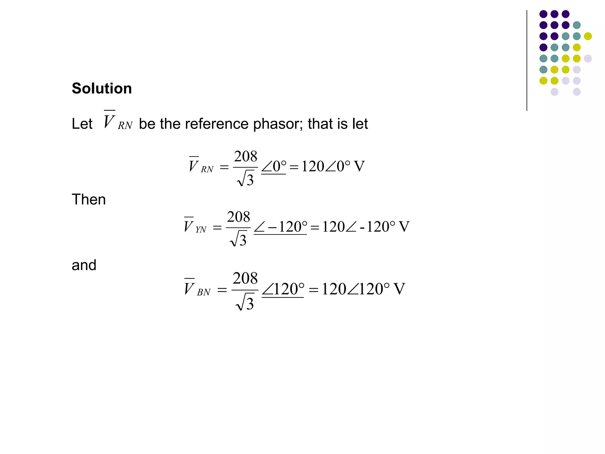
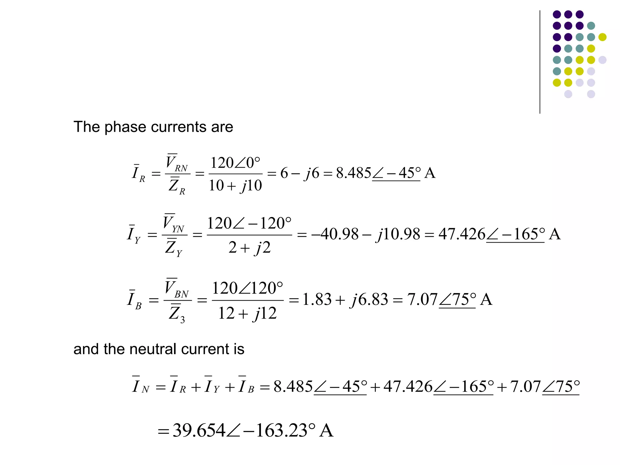
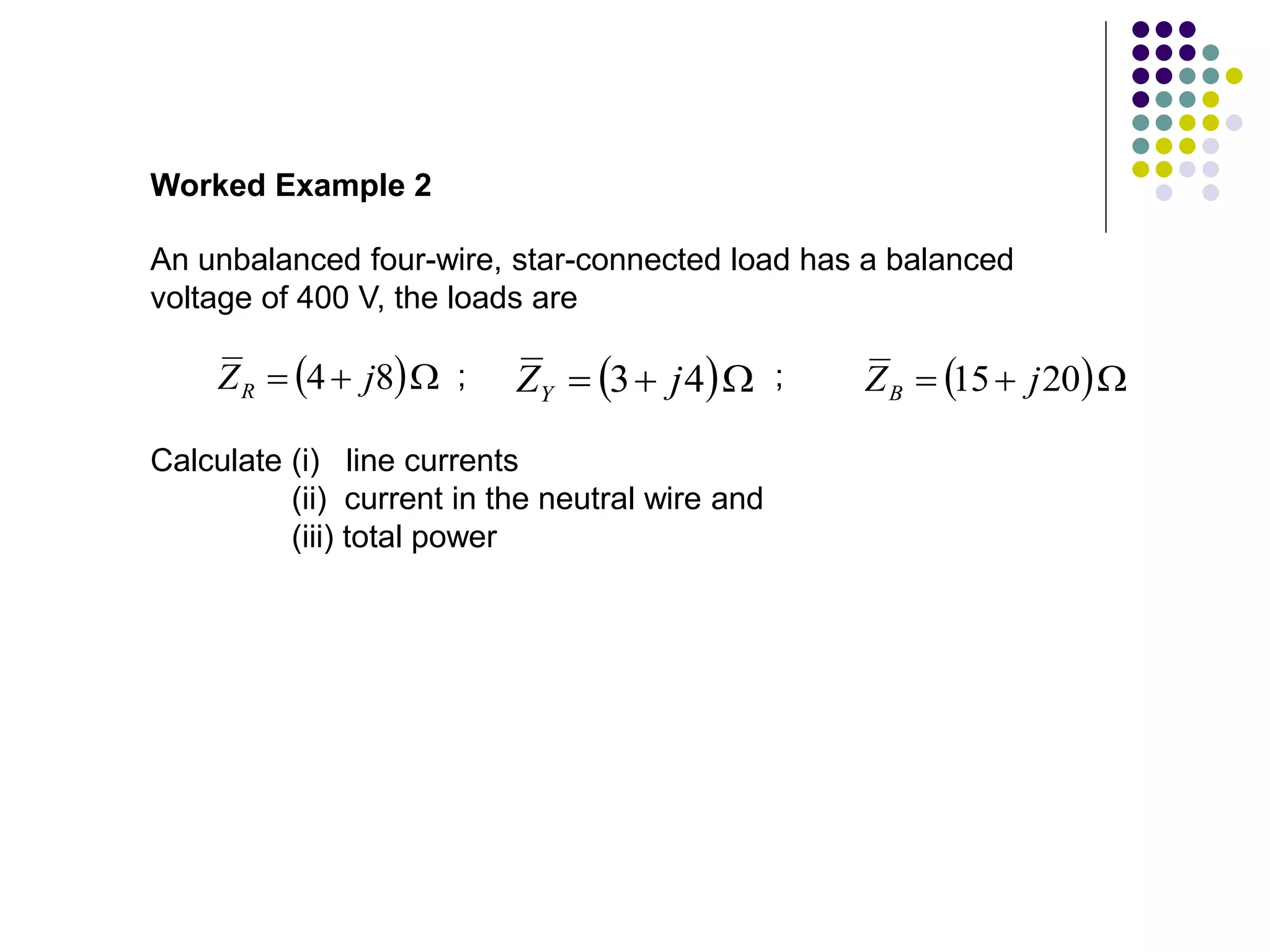
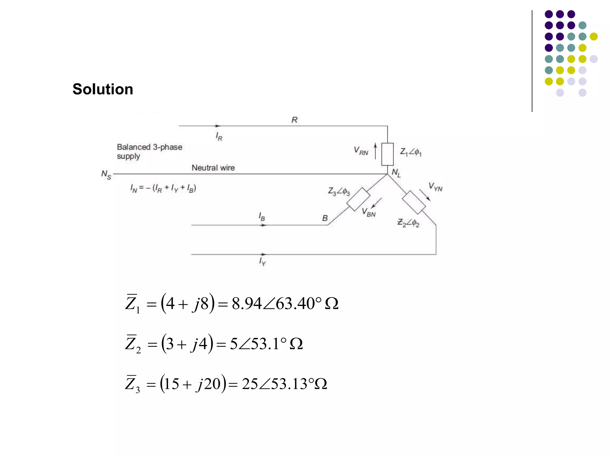
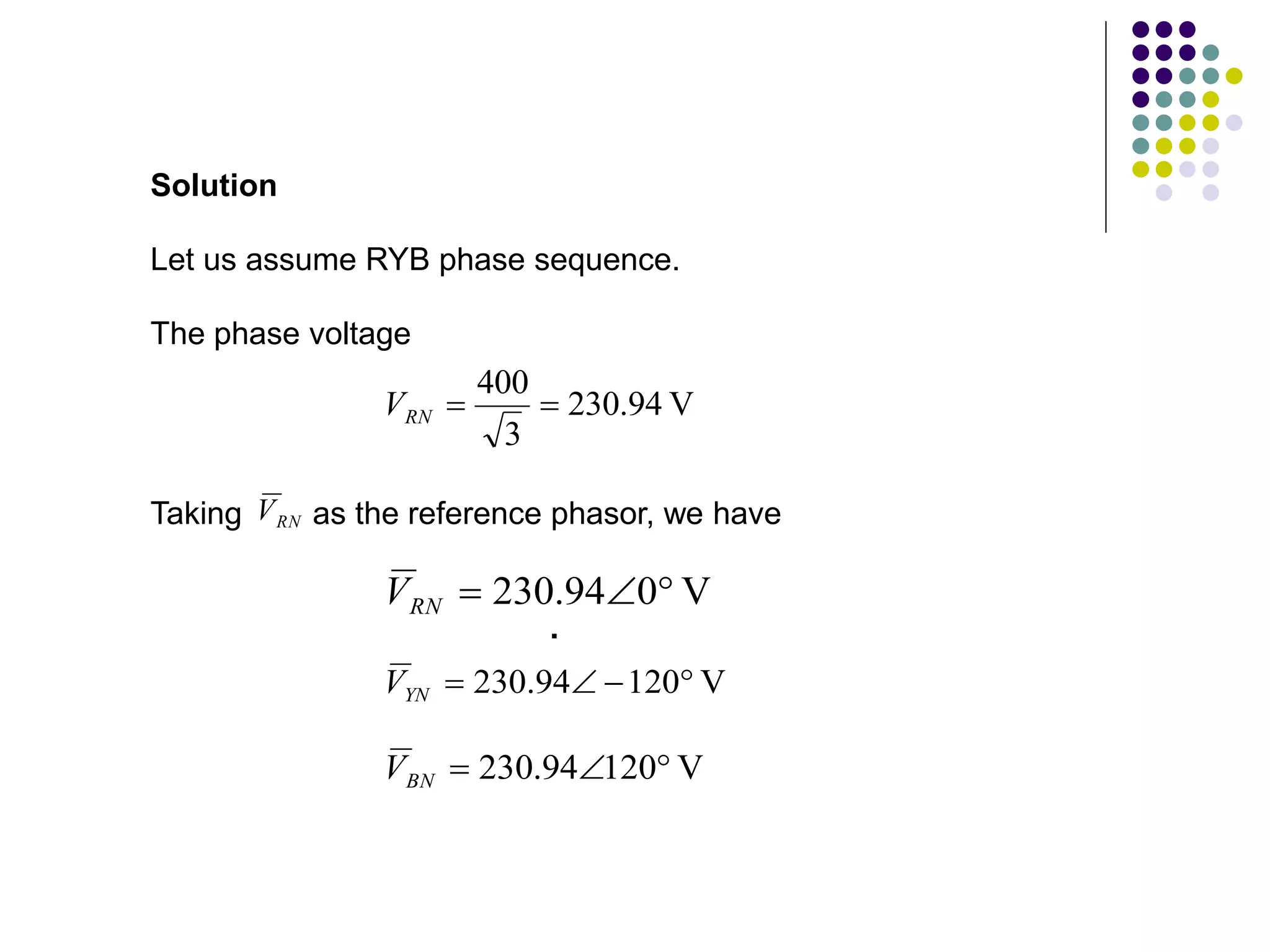
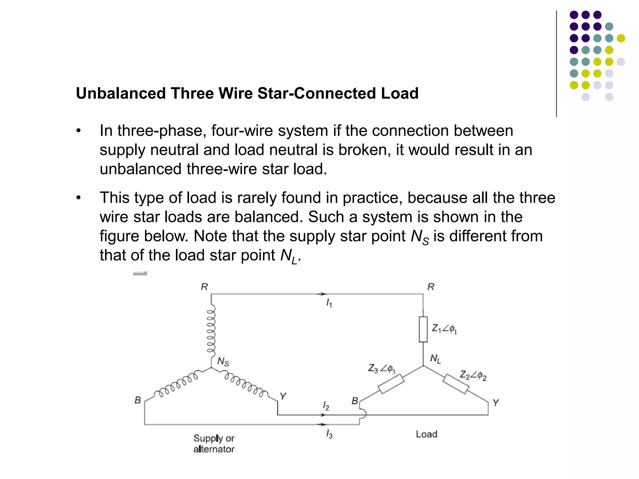
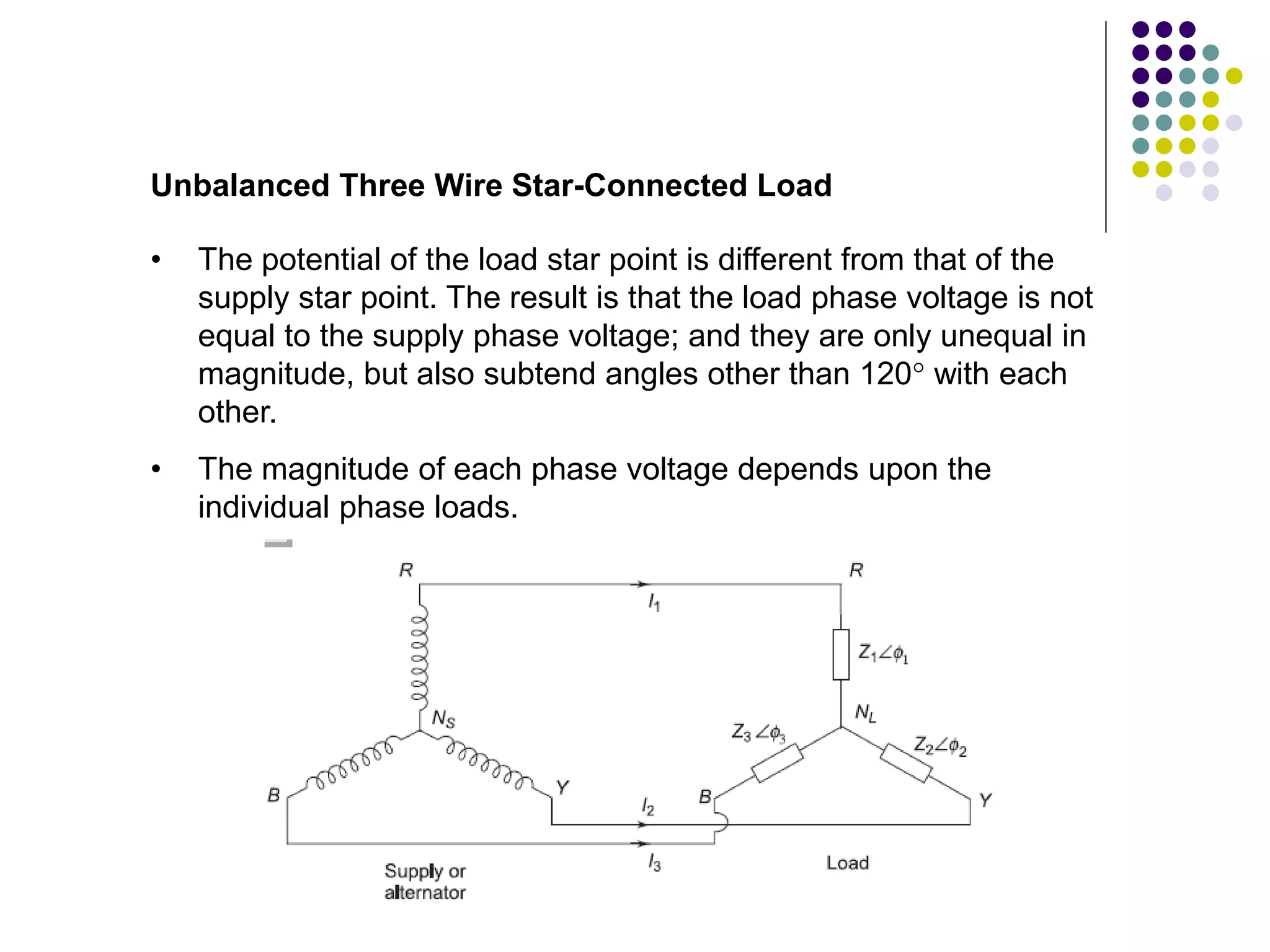
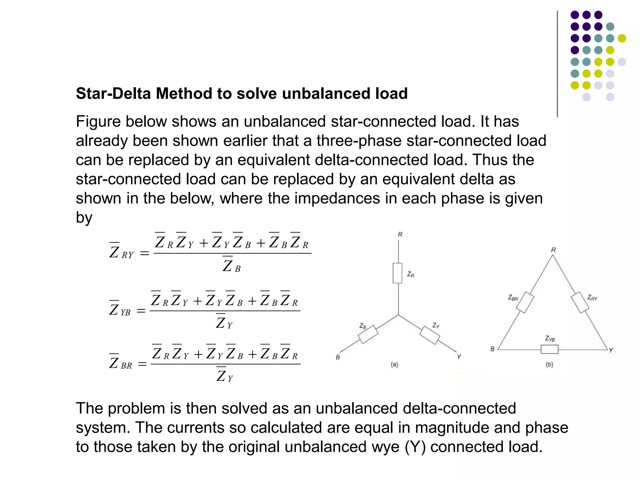
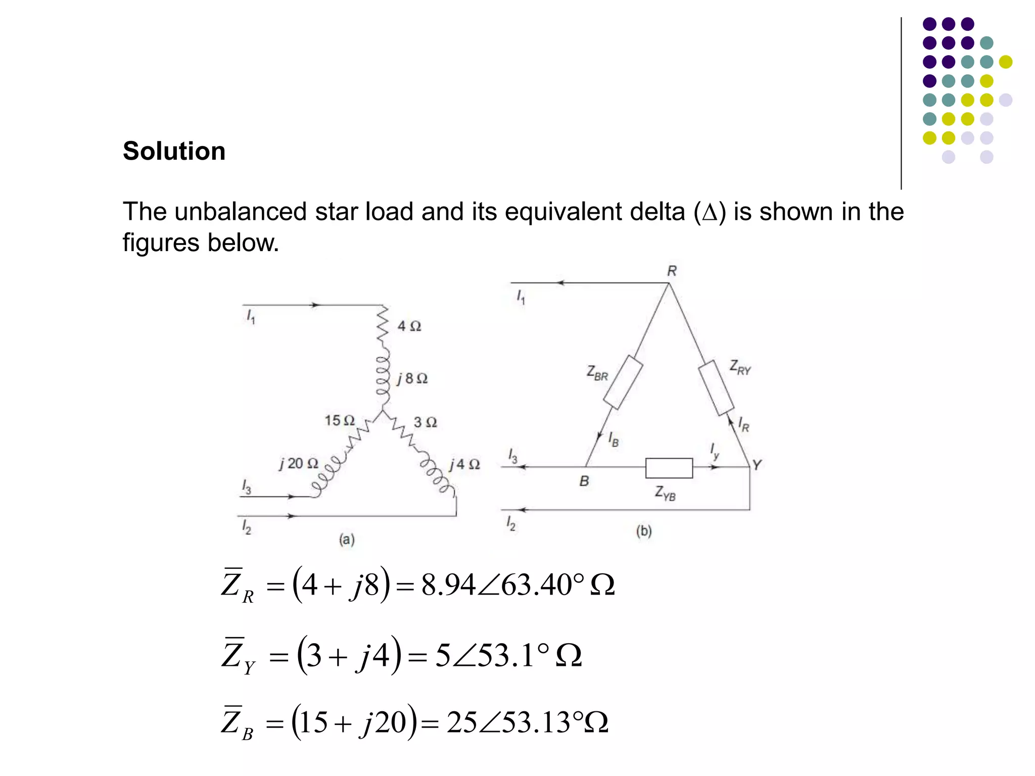
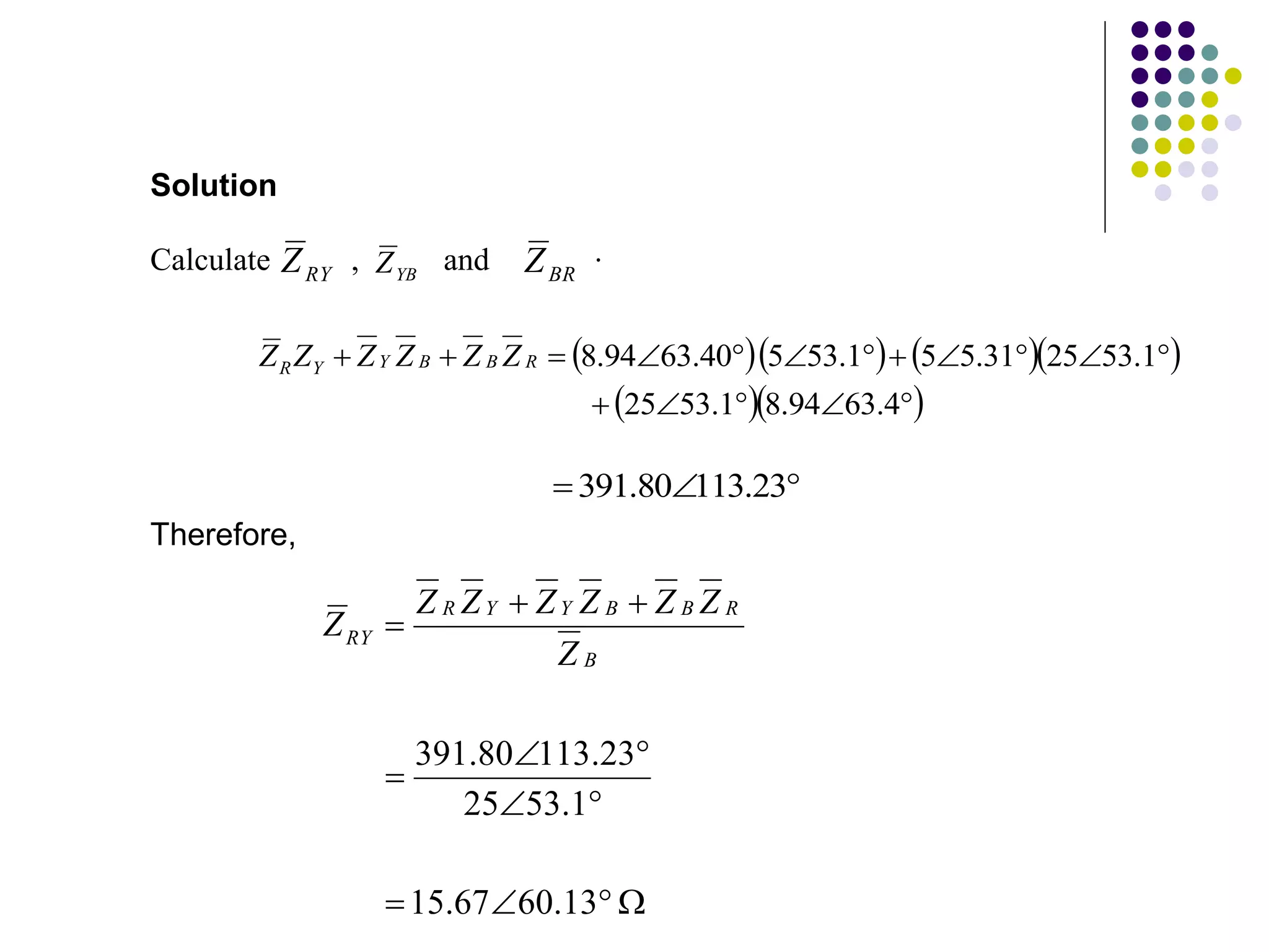
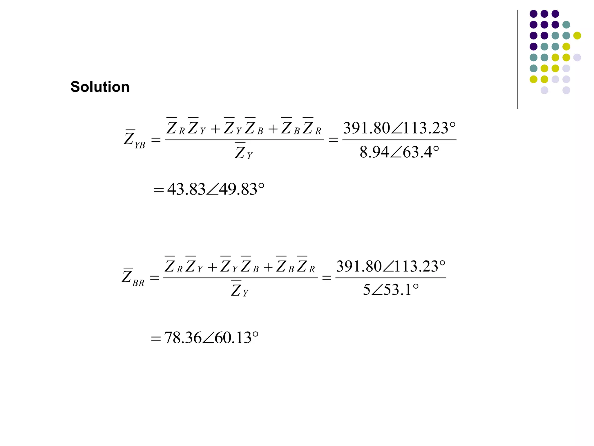
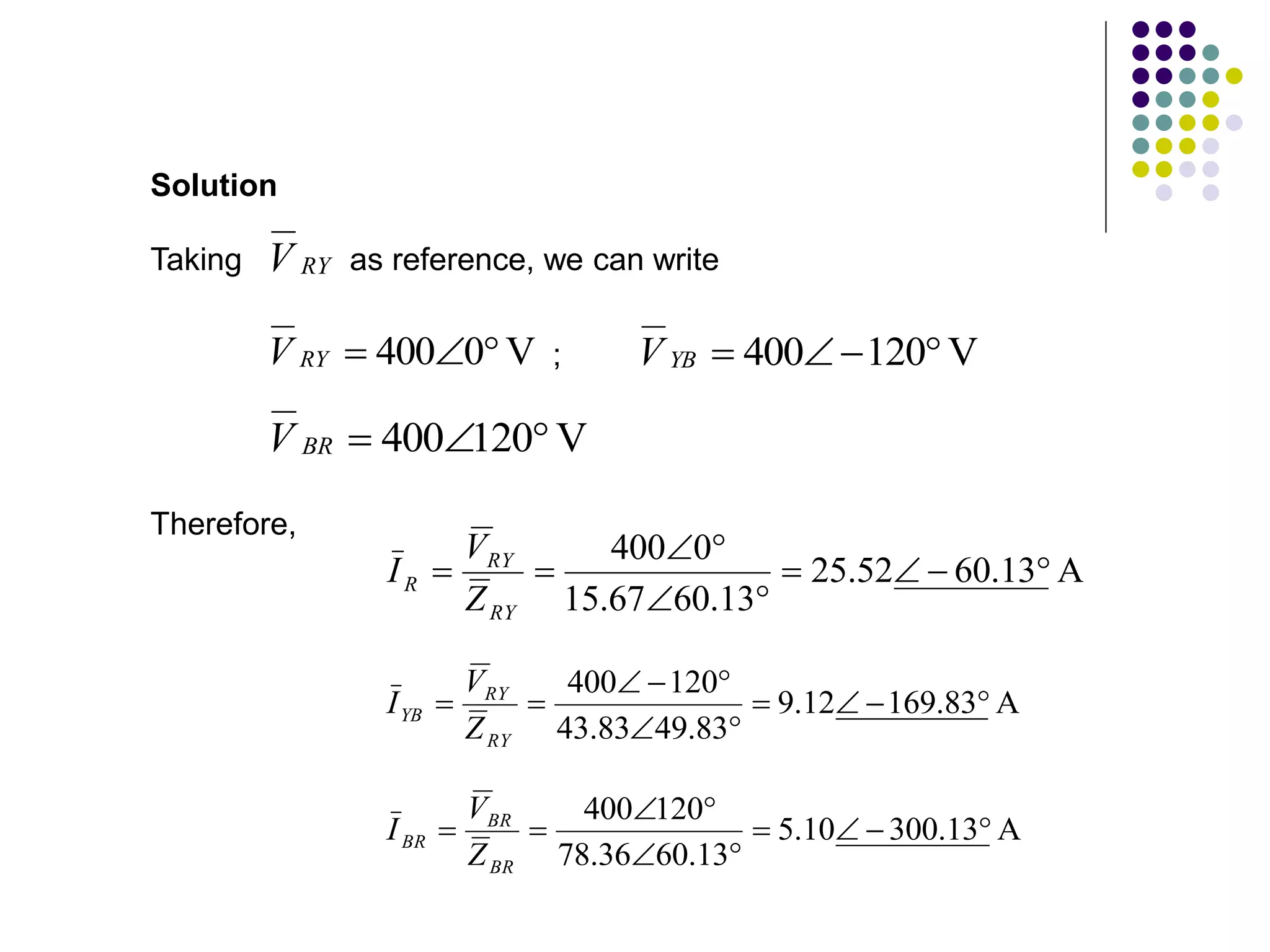
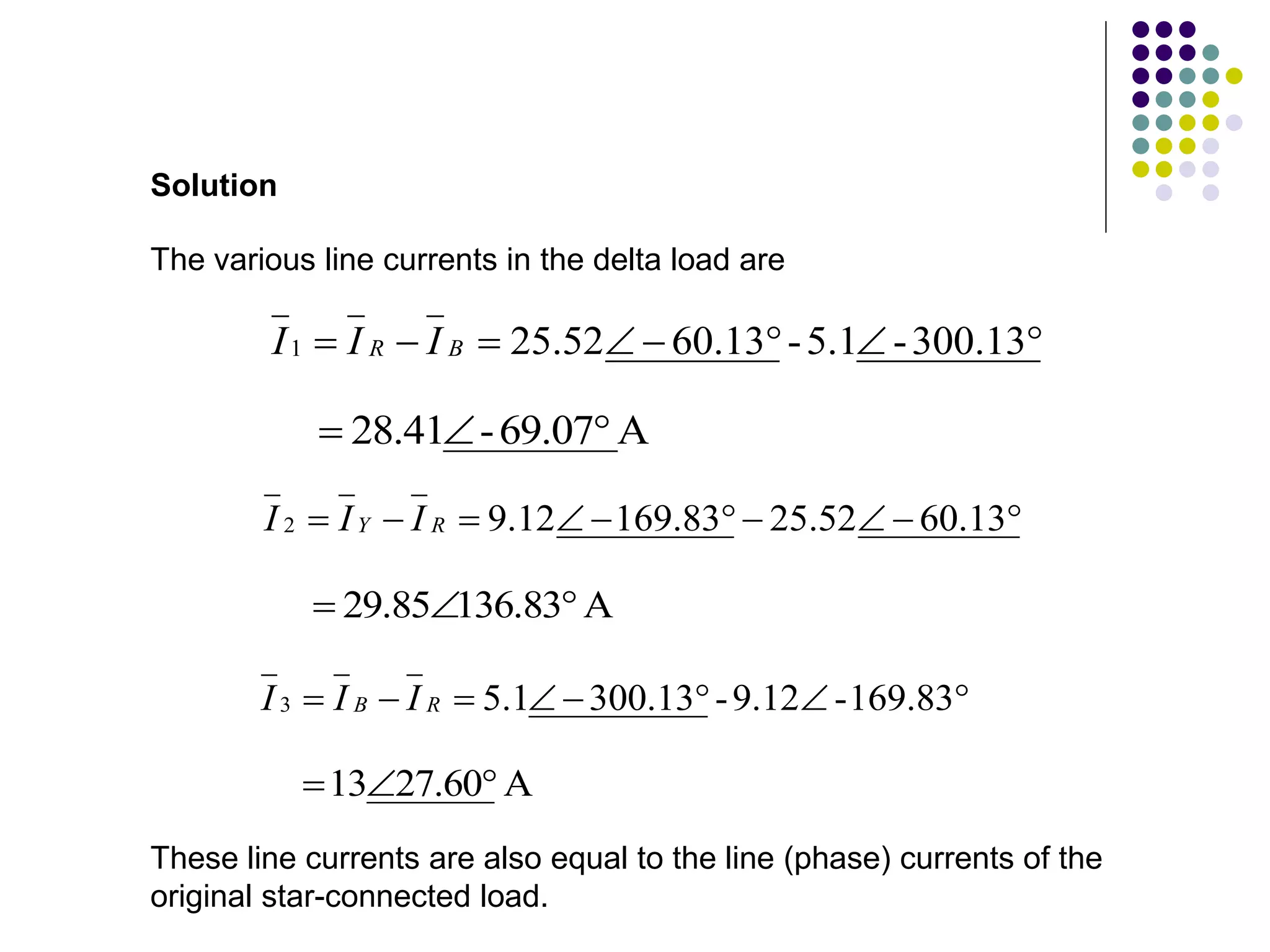
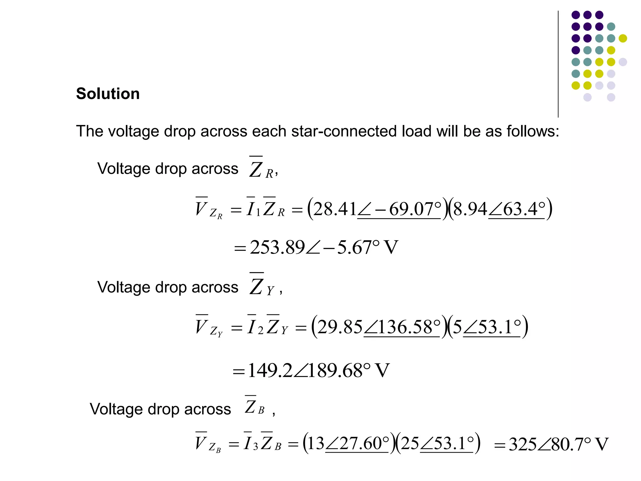
Lecture 4
Unbalanced Three-
Phase Systems
LEARNING OUTCOMES
After completing this lesson you will be able to:
Introduction
So far, we have considered balanced loads connected to balanced
systems. It is enough to solve problems, considering one phase only
on balanced loads; the conditions on other two phases being similar.
Problems on unbalanced three-phase loads are difficult to handle
because conditions in the three phases are different. However, the
source voltages are assumed to be balanced. If the system is a
three-wire system, the currents flowing towards the load in the three
lines must add to zero at any given instant. If the system is a four-
wire system, the sum of the three outgoing line currents is equal to
the return current in the neutral wire. We will now consider different
methods to handle unbalanced star-connected and delta-connected
loads.
An unbalance exists in a circuit when the impedances in
one or more phases differ from the impedances of the other
phases. In such a case, line or phase currents are different
and displaced from one another by unequal angles.
Definition
In practice, we may come across the following unbalanced loads:
1. Unbalanced four-wire star-connected load
2. Unbalanced three-wire star-connected load, and
3. Unbalanced delta-connected load
In practice, we may come across the following unbalanced loads:
1. Unbalanced four-wire star-connected load
2. Unbalanced three-wire star-connected load, and
3. Unbalanced delta-connected load
Figure below shows an unbalanced star load connected to a
balanced 3-phase 4-wire supply.
Unbalanced Four Wire Star-Connected Load
• The star point, NL, of the load is connected to the star point, NS of
the supply.
• It is the simplest case of an unbalanced load because of the
presence of the neutral wire; the star points of the supply NS
(generator) and the load NL are at the same potential.
Unbalanced Four Wire Star-Connected Load (continued)
• It means that the voltage across each load impedance is equal
to the phase voltage of the supply (generator), i.e. the voltages
across the three load impedances are equalised even though
load impedances are unequal.
Unbalanced Four Wire Star-Connected Load (continued)
Taking the phase voltage
V
0

 V
V RN
as reference, and assuming RYB phase sequences, we have the
three phase voltages as follows:
V
0

V
V RN V
120


V
V YN
;
V
120

V
V BN
The phase currents can therefore be determined by Ohm’s law;
Unbalanced Four Wire Star-Connected Load (continued)
A
0
1
1
1
1
1










Z
V
Z
V
Z
V
I RN
R
A
120
120
2
2
1
2
2












Z
V
Z
V
Z
V
I YN
Y
Unbalanced Four Wire Star-Connected Load (continued)
A
120
120
3
3
3
3
3











Z
V
Z
V
Z
V
I B
B
Obviously, the current in each phase (or line) will be different. Hence,
the vector sum of the currents in the three lines is not zero, but is
equal to neutral current, i.e.
Unbalanced Four Wire Star-Connected Load (continued)
0



 B
Y
R
N I
I
I
I
For the system below:
i. Calculate the magnitude of the voltage across each phase
of the load.
ii. Find the magnitude of the current through each phase of
the load.
iii. Determine the neutral current.
iv. Find the total watts, volt-amperes reactive, and volt-amperes.
Assume RYB phase sequence.
Worked Example 1
ZR = (10 + j10)
R
N
Y
B
ZB = (12 + j12) 
ZY = (2 + j2) 
208 V
208 V
208 V
IR
IN
IY
IB
Let be the reference phasor; that is let
Solution
RN
V
V
0
120
0
3
208






RN
V
Then
V
120
-
120
120
3
208







YN
V
and
V
120
120
120
3
208






BN
V
The phase currents are
A
45
485
.
8
6
6
10
10
0
120










 j
j
Z
V
I
R
RN
R
A
165
426
.
47
98
.
10
98
.
40
2
2
120
120












 j
j
Z
V
I
Y
YN
Y
A
75
07
.
7
83
.
6
83
.
1
12
12
120
120
3









 j
j
Z
V
I BN
B
and the neutral current is













 75
07
.
7
165
426
.
47
45
485
.
8
B
Y
R
N I
I
I
I
A
23
.
163
654
.
39 



An unbalanced four-wire, star-connected load has a balanced
voltage of 400 V, the loads are
Worked Example 2
 

 8
4 j
ZR  

 4
3 j
ZY  

 20
15 j
ZB
; ;
Calculate (i) line currents
(ii) current in the neutral wire and
(iii) total power
Solution
  




 40
.
63
94
.
8
8
4
1 j
Z
  




 53.1
5
4
3
2 j
Z
  




 53.13
25
20
15
3 j
Z
Let us assume RYB phase sequence.
Solution
The phase voltage
V
94
.
230
3
400


RN
V
.
Taking as the reference phasor, we have
RN
V
V
0
94
.
230 


RN
V
V
120
94
.
230 



YN
V
V
120
94
.
230 


BN
V
The three line currents are
A
4
.
63
83
.
25
4
.
63
94
.
8
0
94
.
230
1










Z
V
I RN
R
A
1
.
173
188
.
46
1
.
53
5
120
230
2











Z
V
I YN
Y
A
13
.
293
23
.
9
13
.
53
25
120
230
3










Z
V
I B
B
Solution
(i) To find the neutral current, we must add the three line currents.
The neutral current must then be equal and opposite to this sum.
Thus
Solution
 
B
Y
R
N I
I
I
I 



 A
293.13
-
9.23
173.1
-
46.188
4
.
63
83
.
25 










     
 A
48
.
8
62
.
3
54
.
5
85
.
45
09
.
23
56
.
11 j
j
j 







 A
15
.
20
67
.
30 j


In polar form,
A
30
.
33
69
.
36 


R
I
It’s phase with respect to is 33.3, the disposition of all the currents
is shown in the figure below.
Solution
Power in R phase,
Power in Y phase,
  W
75
.
2668
4
83
.
25
2
2



 R
R I
P
  W
77
.
6397
3
18
.
46
2
2



 Y
Y I
P
Power in B phase,
  W
89
.
1277
15
23
.
9
2
2



 B
B I
P
Total power absorbed by the load
W
41
.
10344

B
Y
R
T P
P
P
P 


W
89
.
1277
77
.
6397
75
.
2668 


Unbalanced Three Wire Star-Connected Load
• In three-phase, four-wire system if the connection between
supply neutral and load neutral is broken, it would result in an
unbalanced three-wire star load.
• This type of load is rarely found in practice, because all the three
wire star loads are balanced. Such a system is shown in the
figure below. Note that the supply star point NS is different from
that of the load star point NL.
Unbalanced Three Wire Star-Connected Load
• The potential of the load star point is different from that of the
supply star point. The result is that the load phase voltage is not
equal to the supply phase voltage; and they are only unequal in
magnitude, but also subtend angles other than 120 with each
other.
• The magnitude of each phase voltage depends upon the
individual phase loads.
Unbalanced Three Wire Star-Connected Load
• The potential of the load neutral point changes according to
changes in the impedances of the phases, that is why sometimes
the load neutral is also called a floating neutral point.
• All star-connected, unbalanced loads supplied from polyphase
systems without a neutral wire have floating neutral point.
• The phasor sum of the three unbalanced line currents is zero.
The phase voltage of the load is not of the line voltage.
• The unbalanced three-wire star load is difficult to deal with. It is
because load phase voltages cannot be determined directly from
the given supply line voltages.
There are many methods to solve unbalanced Y-connected loads.
Two frequently used methods are presented here. They are:
Solving Unbalanced Three Wire Star-Connected Loads
1. Star-delta conversion method, and
2. The application of Millman’s theorem
Figure below shows an unbalanced star-connected load. It has
already been shown earlier that a three-phase star-connected load
can be replaced by an equivalent delta-connected load. Thus the
star-connected load can be replaced by an equivalent delta as
shown in the below, where the impedances in each phase is given
by
Star-Delta Method to solve unbalanced load
B
R
B
B
Y
Y
R
RY
Z
Z
Z
Z
Z
Z
Z
Z



Y
R
B
B
Y
Y
R
YB
Z
Z
Z
Z
Z
Z
Z
Z



Y
R
B
B
Y
Y
R
BR
Z
Z
Z
Z
Z
Z
Z
Z



The problem is then solved as an unbalanced delta-connected
system. The currents so calculated are equal in magnitude and phase
to those taken by the original unbalanced wye (Y) connected load.
A 400 V, three-phase supply feeds an unbalanced three-wire, star-
connected load. The branch impedances of the load are
Example
 

 8
4 j
ZR
 

 4
3 j
ZY
 

 20
15 j
ZB
; ;
Find the line currents and voltage across each phase impedance.
Assume RYB sequence.
The unbalanced star load and its equivalent delta () is shown in the
figures below.
Solution
  




 40
.
63
94
.
8
8
4 j
ZR
  




 53.1
5
4
3 j
ZY
  




 53.13
25
20
15 j
ZB












13
.
60
67
.
15
1
.
53
25
23
.
113
80
.
391
B
R
B
B
Y
Y
R
RY
Z
Z
Z
Z
Z
Z
Z
Z
RY
Z YB
Z BR
Z
Calculate , and .
Solution
     
  

















4
.
63
94
.
8
1
.
53
25
1
.
53
25
31
.
5
5
1
.
53
5
40
.
63
94
.
8
R
B
B
Y
Y
R Z
Z
Z
Z
Z
Z


 23
.
113
80
.
391
Therefore,








4
.
63
94
.
8
23
.
113
80
.
391
Y
R
B
B
Y
Y
R
YB
Z
Z
Z
Z
Z
Z
Z
Z
Solution








1
.
53
5
23
.
113
80
.
391
Y
R
B
B
Y
Y
R
BR
Z
Z
Z
Z
Z
Z
Z
Z


 83
.
49
83
.
43


 13
.
60
36
.
78
RY
V
V
0
400 


RY
V
Taking as reference, we can write
Solution
V
120
400 



YB
V
V
120
400 


BR
V
A
13
.
60
52
.
25
13
.
60
67
.
15
0
400










RY
RY
R
Z
V
I
Therefore,
A
83
.
169
12
.
9
83
.
49
83
.
43
120
400











RY
RY
YB
Z
V
I
;
A
13
.
300
10
.
5
13
.
60
36
.
78
120
400










BR
BR
BR
Z
V
I
The various line currents in the delta load are







 300.13
-
5.1
-
13
.
60
52
.
25
1 B
R I
I
I
A
69.07
-
28.41 











 13
.
60
52
.
25
83
.
169
12
.
9
2 R
Y I
I
I
A
136.83
29.85 









 169.83
-
9.12
-
13
.
300
1
.
5
3 R
B I
I
I
A
60
.
27
13 


These line currents are also equal to the line (phase) currents of the
original star-connected load.
Solution
The voltage drop across each star-connected load will be as follows:
Solution
R
Z
Voltage drop across ,
  






 4
.
63
94
.
8
07
.
69
41
.
28
1 R
Z Z
I
V R
V
67
.
5
89
.
253 



Y
Z
Voltage drop across ,
  





 1
.
53
5
58
.
136
85
.
29
2 Y
Z Z
I
V Y
V
68
.
189
2
.
149 


Voltage drop across ,
B
Z
V
7
.
80
325 


  





 1
.
53
25
60
.
27
13
3 B
Z Z
I
V B
END OF FIRST PART
The star-delta conversion method of solving an unbalanced three-
wire star-connected load shown earlier is laborious and involved
lengthy calculations. By using Millman’s theorem, we can solve this
type of problem in a much easier way.
MILLMAN’S METHOD OF SOLVING UNBALANCED LOAD
Millman’s theorem is particularly useful for solving many circuits
which are encountered in both electronics and power applications. In
three-phase circuit analysis, for example, this theorem can be used
to find the potential difference between the star point of a wye-
connected source and the star-point of a star-connected load in an
unbalanced three-wire three-phase circuit.
Generalised Form of Millman’s Theorem
Consider a number of impedances , , , …, which
terminate at common point N’ (see figure below). The other ends
of the impedances are connected to voltage sources numbered
as , , , … . Let N be any other point in the
network.
1
Z 2
Z 3
Z n
Z
1
V 2
V 3
V n
V
Vn
  Zn
Vi
Zi
Z3
Z2
Z1
V2 V3
V1
N
I1 I2 I3 I4 In
N’
Application of Ohm’s law to the circuit leads to the following
equations:
1
'
1
1
!
Z
V
V
I
N
N
Z


2
'
2
2
Z
V
V
I
N
N
Z


3
'
3
3
Z
V
V
I
N
N
Z




n
N
N
n
Zn
Z
V
V
I
'


Vn
  Zn
Vi
Zi
Z3
Z2
Z1
V2 V3
V1
N
I1 I2 I3 I4 In
N’
BEF 23803 - Lecture 4 - Unbalanced Three - Phase Circuits.ppt

BEF 23803 - Lecture 4 - Unbalanced Three - Phase Circuits.ppt

  • 1.
  • 2.
    LEARNING OUTCOMES After completingthis lesson you will be able to:
  • 3.
    Introduction So far, wehave considered balanced loads connected to balanced systems. It is enough to solve problems, considering one phase only on balanced loads; the conditions on other two phases being similar. Problems on unbalanced three-phase loads are difficult to handle because conditions in the three phases are different. However, the source voltages are assumed to be balanced. If the system is a three-wire system, the currents flowing towards the load in the three lines must add to zero at any given instant. If the system is a four- wire system, the sum of the three outgoing line currents is equal to the return current in the neutral wire. We will now consider different methods to handle unbalanced star-connected and delta-connected loads.
  • 4.
    An unbalance existsin a circuit when the impedances in one or more phases differ from the impedances of the other phases. In such a case, line or phase currents are different and displaced from one another by unequal angles. Definition In practice, we may come across the following unbalanced loads: 1. Unbalanced four-wire star-connected load 2. Unbalanced three-wire star-connected load, and 3. Unbalanced delta-connected load
  • 5.
    In practice, wemay come across the following unbalanced loads: 1. Unbalanced four-wire star-connected load 2. Unbalanced three-wire star-connected load, and 3. Unbalanced delta-connected load
  • 6.
    Figure below showsan unbalanced star load connected to a balanced 3-phase 4-wire supply. Unbalanced Four Wire Star-Connected Load • The star point, NL, of the load is connected to the star point, NS of the supply. • It is the simplest case of an unbalanced load because of the presence of the neutral wire; the star points of the supply NS (generator) and the load NL are at the same potential.
  • 7.
    Unbalanced Four WireStar-Connected Load (continued) • It means that the voltage across each load impedance is equal to the phase voltage of the supply (generator), i.e. the voltages across the three load impedances are equalised even though load impedances are unequal.
  • 8.
    Unbalanced Four WireStar-Connected Load (continued) Taking the phase voltage V 0   V V RN as reference, and assuming RYB phase sequences, we have the three phase voltages as follows: V 0  V V RN V 120   V V YN ; V 120  V V BN
  • 9.
    The phase currentscan therefore be determined by Ohm’s law; Unbalanced Four Wire Star-Connected Load (continued) A 0 1 1 1 1 1           Z V Z V Z V I RN R A 120 120 2 2 1 2 2             Z V Z V Z V I YN Y
  • 10.
    Unbalanced Four WireStar-Connected Load (continued) A 120 120 3 3 3 3 3            Z V Z V Z V I B B
  • 11.
    Obviously, the currentin each phase (or line) will be different. Hence, the vector sum of the currents in the three lines is not zero, but is equal to neutral current, i.e. Unbalanced Four Wire Star-Connected Load (continued) 0     B Y R N I I I I
  • 12.
    For the systembelow: i. Calculate the magnitude of the voltage across each phase of the load. ii. Find the magnitude of the current through each phase of the load. iii. Determine the neutral current. iv. Find the total watts, volt-amperes reactive, and volt-amperes. Assume RYB phase sequence. Worked Example 1 ZR = (10 + j10) R N Y B ZB = (12 + j12)  ZY = (2 + j2)  208 V 208 V 208 V IR IN IY IB
  • 13.
    Let be thereference phasor; that is let Solution RN V V 0 120 0 3 208       RN V Then V 120 - 120 120 3 208        YN V and V 120 120 120 3 208       BN V
  • 14.
    The phase currentsare A 45 485 . 8 6 6 10 10 0 120            j j Z V I R RN R A 165 426 . 47 98 . 10 98 . 40 2 2 120 120              j j Z V I Y YN Y A 75 07 . 7 83 . 6 83 . 1 12 12 120 120 3           j j Z V I BN B and the neutral current is               75 07 . 7 165 426 . 47 45 485 . 8 B Y R N I I I I A 23 . 163 654 . 39    
  • 15.
    An unbalanced four-wire,star-connected load has a balanced voltage of 400 V, the loads are Worked Example 2     8 4 j ZR     4 3 j ZY     20 15 j ZB ; ; Calculate (i) line currents (ii) current in the neutral wire and (iii) total power
  • 16.
    Solution        40 . 63 94 . 8 8 4 1 j Z         53.1 5 4 3 2 j Z         53.13 25 20 15 3 j Z
  • 17.
    Let us assumeRYB phase sequence. Solution The phase voltage V 94 . 230 3 400   RN V . Taking as the reference phasor, we have RN V V 0 94 . 230    RN V V 120 94 . 230     YN V V 120 94 . 230    BN V
  • 18.
    The three linecurrents are A 4 . 63 83 . 25 4 . 63 94 . 8 0 94 . 230 1           Z V I RN R A 1 . 173 188 . 46 1 . 53 5 120 230 2            Z V I YN Y A 13 . 293 23 . 9 13 . 53 25 120 230 3           Z V I B B Solution
  • 19.
    (i) To findthe neutral current, we must add the three line currents. The neutral current must then be equal and opposite to this sum. Thus Solution   B Y R N I I I I      A 293.13 - 9.23 173.1 - 46.188 4 . 63 83 . 25                   A 48 . 8 62 . 3 54 . 5 85 . 45 09 . 23 56 . 11 j j j          A 15 . 20 67 . 30 j   In polar form, A 30 . 33 69 . 36    R I
  • 20.
    It’s phase withrespect to is 33.3, the disposition of all the currents is shown in the figure below. Solution
  • 21.
    Power in Rphase, Power in Y phase,   W 75 . 2668 4 83 . 25 2 2     R R I P   W 77 . 6397 3 18 . 46 2 2     Y Y I P Power in B phase,   W 89 . 1277 15 23 . 9 2 2     B B I P Total power absorbed by the load W 41 . 10344  B Y R T P P P P    W 89 . 1277 77 . 6397 75 . 2668   
  • 22.
    Unbalanced Three WireStar-Connected Load • In three-phase, four-wire system if the connection between supply neutral and load neutral is broken, it would result in an unbalanced three-wire star load. • This type of load is rarely found in practice, because all the three wire star loads are balanced. Such a system is shown in the figure below. Note that the supply star point NS is different from that of the load star point NL.
  • 23.
    Unbalanced Three WireStar-Connected Load • The potential of the load star point is different from that of the supply star point. The result is that the load phase voltage is not equal to the supply phase voltage; and they are only unequal in magnitude, but also subtend angles other than 120 with each other. • The magnitude of each phase voltage depends upon the individual phase loads.
  • 24.
    Unbalanced Three WireStar-Connected Load • The potential of the load neutral point changes according to changes in the impedances of the phases, that is why sometimes the load neutral is also called a floating neutral point. • All star-connected, unbalanced loads supplied from polyphase systems without a neutral wire have floating neutral point. • The phasor sum of the three unbalanced line currents is zero. The phase voltage of the load is not of the line voltage. • The unbalanced three-wire star load is difficult to deal with. It is because load phase voltages cannot be determined directly from the given supply line voltages.
  • 25.
    There are manymethods to solve unbalanced Y-connected loads. Two frequently used methods are presented here. They are: Solving Unbalanced Three Wire Star-Connected Loads 1. Star-delta conversion method, and 2. The application of Millman’s theorem
  • 26.
    Figure below showsan unbalanced star-connected load. It has already been shown earlier that a three-phase star-connected load can be replaced by an equivalent delta-connected load. Thus the star-connected load can be replaced by an equivalent delta as shown in the below, where the impedances in each phase is given by Star-Delta Method to solve unbalanced load B R B B Y Y R RY Z Z Z Z Z Z Z Z    Y R B B Y Y R YB Z Z Z Z Z Z Z Z    Y R B B Y Y R BR Z Z Z Z Z Z Z Z    The problem is then solved as an unbalanced delta-connected system. The currents so calculated are equal in magnitude and phase to those taken by the original unbalanced wye (Y) connected load.
  • 27.
    A 400 V,three-phase supply feeds an unbalanced three-wire, star- connected load. The branch impedances of the load are Example     8 4 j ZR     4 3 j ZY     20 15 j ZB ; ; Find the line currents and voltage across each phase impedance. Assume RYB sequence.
  • 28.
    The unbalanced starload and its equivalent delta () is shown in the figures below. Solution         40 . 63 94 . 8 8 4 j ZR         53.1 5 4 3 j ZY         53.13 25 20 15 j ZB
  • 29.
                13 . 60 67 . 15 1 . 53 25 23 . 113 80 . 391 B R B B Y Y R RY Z Z Z Z Z Z Z Z RY Z YB Z BR Z Calculate, and . Solution                           4 . 63 94 . 8 1 . 53 25 1 . 53 25 31 . 5 5 1 . 53 5 40 . 63 94 . 8 R B B Y Y R Z Z Z Z Z Z    23 . 113 80 . 391 Therefore,
  • 30.
  • 31.
    RY V V 0 400    RY V Taking asreference, we can write Solution V 120 400     YB V V 120 400    BR V A 13 . 60 52 . 25 13 . 60 67 . 15 0 400           RY RY R Z V I Therefore, A 83 . 169 12 . 9 83 . 49 83 . 43 120 400            RY RY YB Z V I ; A 13 . 300 10 . 5 13 . 60 36 . 78 120 400           BR BR BR Z V I
  • 32.
    The various linecurrents in the delta load are         300.13 - 5.1 - 13 . 60 52 . 25 1 B R I I I A 69.07 - 28.41              13 . 60 52 . 25 83 . 169 12 . 9 2 R Y I I I A 136.83 29.85            169.83 - 9.12 - 13 . 300 1 . 5 3 R B I I I A 60 . 27 13    These line currents are also equal to the line (phase) currents of the original star-connected load. Solution
  • 33.
    The voltage dropacross each star-connected load will be as follows: Solution R Z Voltage drop across ,           4 . 63 94 . 8 07 . 69 41 . 28 1 R Z Z I V R V 67 . 5 89 . 253     Y Z Voltage drop across ,          1 . 53 5 58 . 136 85 . 29 2 Y Z Z I V Y V 68 . 189 2 . 149    Voltage drop across , B Z V 7 . 80 325             1 . 53 25 60 . 27 13 3 B Z Z I V B
  • 34.
  • 35.
    The star-delta conversionmethod of solving an unbalanced three- wire star-connected load shown earlier is laborious and involved lengthy calculations. By using Millman’s theorem, we can solve this type of problem in a much easier way. MILLMAN’S METHOD OF SOLVING UNBALANCED LOAD Millman’s theorem is particularly useful for solving many circuits which are encountered in both electronics and power applications. In three-phase circuit analysis, for example, this theorem can be used to find the potential difference between the star point of a wye- connected source and the star-point of a star-connected load in an unbalanced three-wire three-phase circuit. Generalised Form of Millman’s Theorem
  • 36.
    Consider a numberof impedances , , , …, which terminate at common point N’ (see figure below). The other ends of the impedances are connected to voltage sources numbered as , , , … . Let N be any other point in the network. 1 Z 2 Z 3 Z n Z 1 V 2 V 3 V n V Vn   Zn Vi Zi Z3 Z2 Z1 V2 V3 V1 N I1 I2 I3 I4 In N’
  • 37.
    Application of Ohm’slaw to the circuit leads to the following equations: 1 ' 1 1 ! Z V V I N N Z   2 ' 2 2 Z V V I N N Z   3 ' 3 3 Z V V I N N Z     n N N n Zn Z V V I '   Vn   Zn Vi Zi Z3 Z2 Z1 V2 V3 V1 N I1 I2 I3 I4 In N’