Download as PDF, PPTX

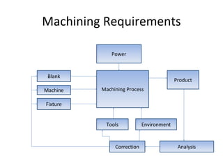
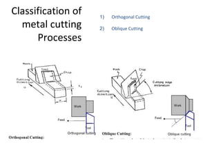
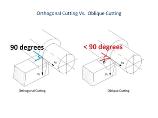
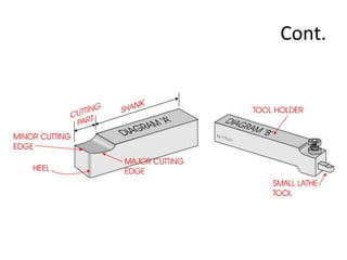
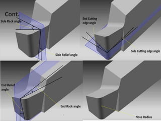
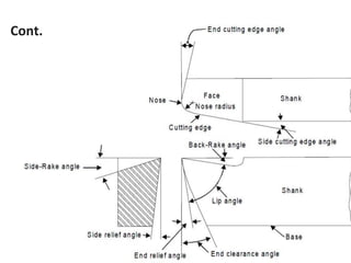
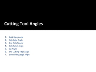
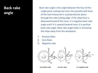
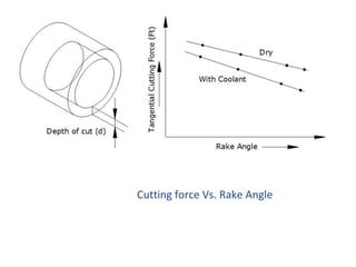
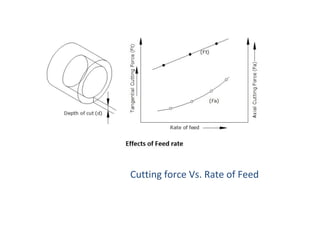
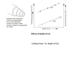
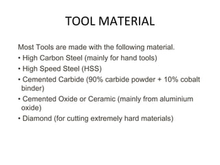
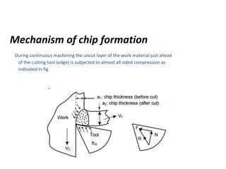
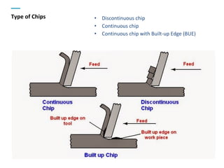
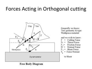
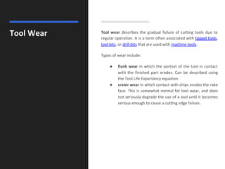


This document provides information on metal cutting processes and machining technology. It discusses: - The purpose, principles, and definition of machining as a process to produce parts to desired dimensions and surface finish through chip removal. - Classification of metal cutting processes as orthogonal or oblique cutting. It also discusses cutting tool angles like back rake angle and relief angles. - Factors that affect cutting forces like rake angle, feed rate, and depth of cut. - Tool designation systems like ASA and common tool materials like high-speed steel and cemented carbide. - The mechanism of chip formation and different chip types like continuous, discontinuous, and chips with built-up edge