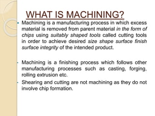
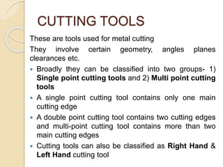
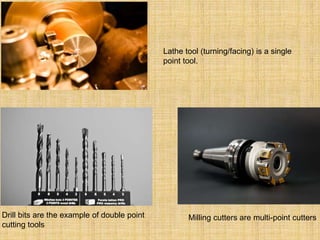
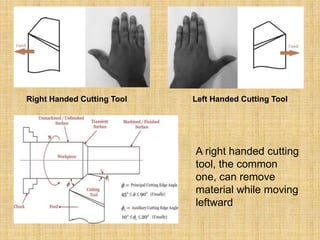
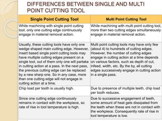
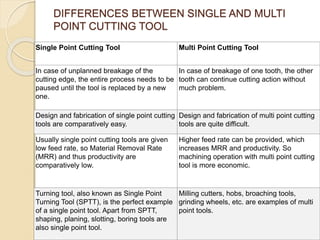
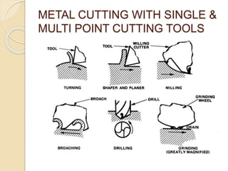
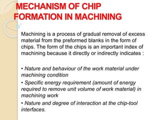
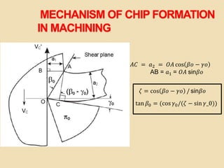
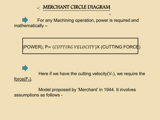
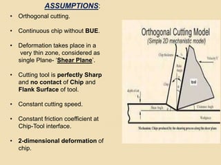
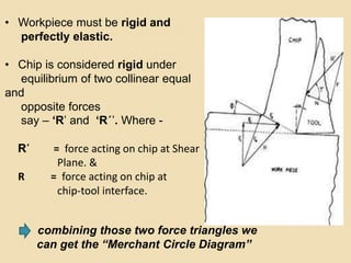
This document provides an overview of machining, defining it as a process that removes excess material from a parent material using cutting tools to achieve desired specifications. It discusses various types of cutting tools, their classifications, and compares single-point and multi-point tools, emphasizing their operational differences and efficiency. Additionally, the document examines chip formation mechanisms, types of cutting, and various factors influencing the machining process, including cutting forces and energy consumption.