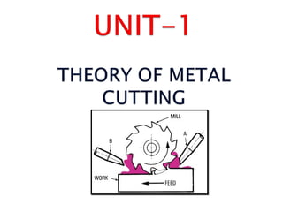
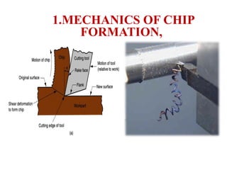
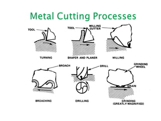
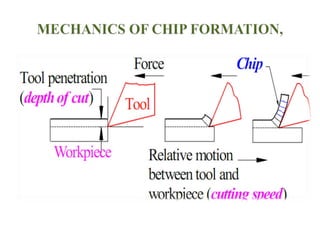
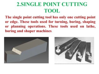
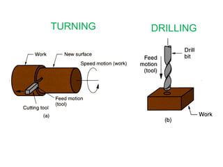
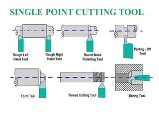
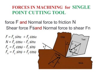
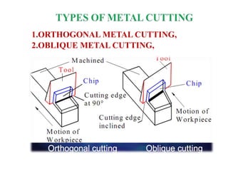
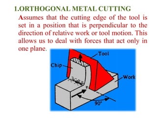
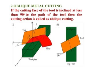
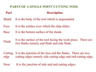
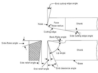
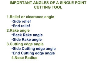
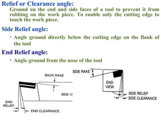
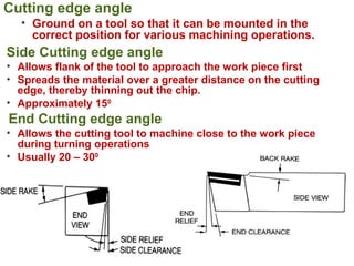
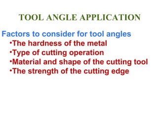
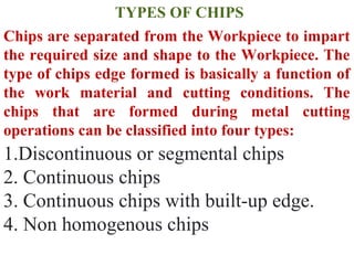
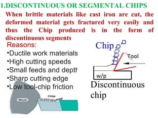
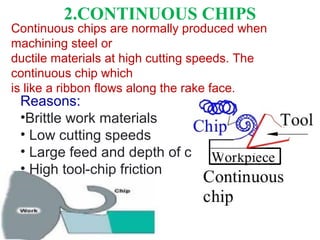
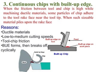
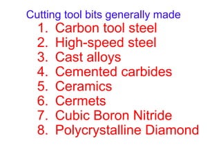
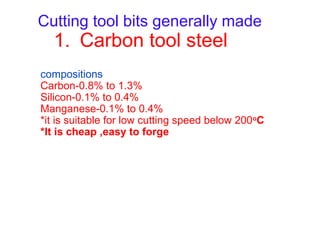
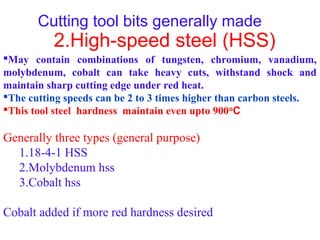
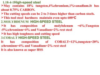
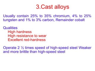
Prepared by
Mr.L.NARAYANAN,M.E.,
ASSISTANT PROFESSORS,
MECHANICAL DEPARTMENT.
1.Mechanics Of Chip Formation,
2.Single Point Cutting Tool,
a.Forces In Machining,
3.Types Of Chips
4.Cutting Temperature
5.Cutting Tools – Nomenclature,
6.Orthogonal Metal Cutting
7.Cutting Tool Materials
8.Tool Wear, Tool Life, Surface Finish,
9.Cutting Fluids And Machinability
Cast, formed and shaped products may need further
machining operations to give them the desired final shape,
after removal of extra material in the form of chips.
Machining processes or Metal cutting
process is defined as remove unwanted
material from a work piece by
1.CUTTING ( As in case of machine tools like lathe, shaper etc)
2.ABRASIVE ( As in case of a grinding wheel)
3.NON TRADITIONAL ( Processes such as EDM, ECM Etc.)
THEORY OF METAL CUTTING
1.MECHANICS OF CHIP
FORMATION,material to form a chip As chip is removed, new surface is exposed
(a) A cross sectional view of the machining process, (b) tool with‑
negative rake angle; compare with positive rake angle in (a).
2.SINGLE POINT CUTTING
TOOL
The single point cutting tool has only one cutting point
or edge. These tools used for turning, boring, shaping
or planning operations. These tools used on lathe,
boring and shaper machines.
Three most common machining processes: (a) turning,
TURNING DRILLING
force F and Normal force to friction N
Shear force Fsand Normal force to shear Fn
 The metal cutting is done by a relative motion
between the work piece and the hard edge of a
cutting tool. Metal cutting could be done either by
a single point cutting tool or a multi point cutting
tool. There are two basic types of metal cutting by
a single point cutting tool.
1.ORTHOGONAL METAL CUTTING,
2.OBLIQUE METAL CUTTING,
1.ORTHOGONAL METAL CUTTING
Assumes that the cutting edge of the tool is
set in a position that is perpendicular to the
direction of relative work or tool motion. This
allows us to deal with forces that act only in
one plane.
2.OBLIQUE METAL CUTTING,
If the cutting face of the tool is inclined at less
than 90o
to the path of the tool then the
cutting action is called as oblique cutting.
S.N
o. ORTHOGONAL METAL CUTTING OBLIQUE METAL CUTTING
1.
Cutting edge of the tool is
perpendicular to the direction
of tool travel.
The cutting edge is inclined at an
angle less than 90o
 to the
direction of tool travel.
2.
The direction of chip flow is
perpendicular to the cutting
edge.
The chip flows on the tool face
making an angle.
3.
The chip coils in a tight flat
spiral
The chip flows side ways in a long
curl.
4.
For same feed and depth of cut
the force which shears the metal
acts on a smaller areas.  So the
life of the tool is less.
The cutting force acts on larger
area and so tool life is more.
5. Produces sharp corners.
Produces a chamfer at the end of
the cut
6.
Smaller length of cutting edge is
in contact with the work.
For the same depth of cut greater
length of cutting edge is in
contact with the work.
7.
Generally parting off in lathe,
broaching and slotting operations
are done in this method.
This method of cutting is used in
almost all machining operations.
Elements of Metal Cutting
1.Cutting speed : The relative surface speed between the tool &
the job. It is the distance traveled by work surface related to the
cutting edge of Tool v = πdN / 1000 m / min
2.Feed (s) : The motion of cutting edge of tool with reference to
one revolution of work piece. 
3.Depth of cut (t) : It is measured perpendicular to axis of work
piece and in straight turning in one pass. This can be estimated
from the relation t = ( D - d ) / 2 mm
4.Undeformed chip (Fc) : The cross sectional area of chip before
it is removed from work piece. it is equal to the product of feed
and depth of cut. Fc = s x t mm2
All tools have a major and minor cutting edge. The major
cutting edge removes bulk of material. Where as the minor
cutting edge gives good surface finish.
Elements of Metal Cutting
3.SINGLE POINT CUTTING TOOLS
Nomenclature,
Part Description
Shank It is the body of the tool which is ungrounded.
Face It is the surface over which the chip slides.
Base It is the bottom surface of the shank.
Flank
It is the surface of the tool facing the work piece. There are
two flanks namely end flank and side flank.
Cutting
edge
It is the junction of the face end the flanks. There are two
cutting edges namely side cutting edge and end cutting edge.
Nose It is the junction of side and end cutting edges.
PARTS OF A SINGLE POINT CUTTING TOOL
IMPORTANT ANGLES OF A SINGLE POINT
CUTTING TOOL
1.Relief or clearance angle
•Side relief
•End relief
2.Rake angle
•Back Rake angle
•Side Rake angle
3.Cutting edge angle
•Side Cutting edge angle
•End Cutting edge angle
4.Nose Radius
Relief or Clearance angle:
Ground on the end and side faces of a tool to prevent it from
rubbing on the work piece. To enable only the cutting edge to
touch the work piece.
Side Relief angle:
• Angle ground directly below the cutting edge on the flank of
the tool
End Relief angle:
• Angle ground from the nose of the tool
Cutting edge angle
• Ground on a tool so that it can be mounted in the
correct position for various machining operations.
Side Cutting edge angle
• Allows flank of the tool to approach the work piece first
• Spreads the material over a greater distance on the cutting
edge, thereby thinning out the chip.
• Approximately 150
End Cutting edge angle
• Allows the cutting tool to machine close to the work piece
during turning operations
• Usually 20 – 300
TOOL ANGLE APPLICATION
Factors to consider for tool angles
•The hardness of the metal
•Type of cutting operation
•Material and shape of the cutting tool
•The strength of the cutting edge
TYPES OF CHIPS
Chips are separated from the Workpiece to impart
the required size and shape to the Workpiece. The
type of chips edge formed is basically a function of
the work material and cutting conditions. The
chips that are formed during metal cutting
operations can be classified into four types:
1.Discontinuous or segmental chips
2. Continuous chips
3. Continuous chips with built-up edge.
4. Non homogenous chips
When brittle materials like cast iron are cut, the
deformed material gets fractured very easily and
thus the Chip produced is in the form of
discontinuous segments
Reasons:
•Ductile work materials
•High cutting speeds
•Small feeds and depths
•Sharp cutting edge
•Low tool-chip friction
1.DISCONTINUOUS OR SEGMENTAL CHIPS
2.CONTINUOUS CHIPS
Continuous chips are normally produced when
machining steel or
ductile materials at high cutting speeds. The
continuous chip which
is like a ribbon flows along the rake face.
Reasons:
•Brittle work materials
• Low cutting speeds
• Large feed and depth of cut
• High tool-chip friction
3. Continuous chips with built-up edge.
When the friction between tool and chip is high while
machining ductile materials, some particles of chip adhere
to the tool rake face near the tool tip. When such sizeable
material piles upon the rake face
Reasons:
•Ductile materials
•Low-to-medium cutting speeds
•Tool-chip friction
•BUE forms, then breaks off,
cyclically
Cutting Tool Properties
1.Hardness
Cutting tool material must be 1 1/2 times harder than the
material it is being used to machine. hardness and strength at
high temperatures.
Capable of maintaining a red hardness during machining
operation
Red hardness: ability of cutting tool to maintain sharp cutting
edge at elevated temp.
It is also sometimes referred to as hot hardness or hot strength
2.Wear Resistance
Able to maintain sharpened edge throughout the cutting
operation
Same as abrasive resistance
3.Shock Resistance
Able to take the cutting loads and forces
4.Shape and Configuration
Must be available for use in different sizes and shapes.
CUTTING TOOL MATERIALS
A cutting tool is any tool that is used to remove
metal from the work piece by means of shear
deformation.
It is one of most important components in
machining process
It must be made of a material harder than the
material which is to be cut, and the tool must be
able to withstand the heat generated in the metal
cutting process.
Two basic types
•Single point
•Multiple point
SINGLE POINT CUTTING TOOL
MULTI POINT CUTTING TOOL
Cutting tool bits generally made
1. Carbon tool steel
2. High-speed steel
3. Cast alloys
4. Cemented carbides
5. Ceramics
6. Cermets
7. Cubic Boron Nitride
8. Polycrystalline Diamond
Cutting tool bits generally made
1. Carbon tool steel
compositions
Carbon-0.8% to 1.3%
Silicon-0.1% to 0.4%
Manganese-0.1% to 0.4%
*it is suitable for low cutting speed below 200o
C
*It is cheap ,easy to forge
Cutting tool bits generally made
2.High-speed steel (HSS)
May contain combinations of tungsten, chromium, vanadium,
molybdenum, cobalt can take heavy cuts, withstand shock and
maintain sharp cutting edge under red heat.
The cutting speeds can be 2 to 3 times higher than carbon steels.
This tool steel hardness maintain even upto 900o
C
Generally three types (general purpose)
1.18-4-1 HSS
2.Molybdenum hss
3.Cobalt hss
Cobalt added if more red hardness desired
1.18-4-1High-speed steel
May contains 18% tungsten,4%chromium,1%vanadium.It has
about 0.75% CARBON.
The cutting speeds can be 2 to 3 times higher than carbon steels.
This tool steel hardness maintain even upto 600o
C
2.MOLYBDENUM HIGH-SPEED STEEL
It has composition of molybdenum =6%;Tungsten
-5%;chrominm=4% and Vanadium=2% rest steel
It has high toughness and cutting speed
3.COBALT HIGH-SPEED STEEL
It has composition of COBALT=12%,tungsten=20%
;chrominm=4% and Vanadium=2% rest steel
It is also known as super HSS
3.Cast alloys
Usually contain 25% to 35% chromium, 4% to 25%
tungsten and 1% to 3% carbon, Remainder cobalt
Qualities
High hardness
High resistance to wear
Excellent red-hardness
Operate 2 ½ times speed of high-speed steel Weaker
and more brittle than high-speed steel

Unit1

  • 1.
  • 3.
    1.Mechanics Of ChipFormation, 2.Single Point Cutting Tool, a.Forces In Machining, 3.Types Of Chips 4.Cutting Temperature 5.Cutting Tools – Nomenclature, 6.Orthogonal Metal Cutting 7.Cutting Tool Materials 8.Tool Wear, Tool Life, Surface Finish, 9.Cutting Fluids And Machinability
  • 4.
    Cast, formed andshaped products may need further machining operations to give them the desired final shape, after removal of extra material in the form of chips. Machining processes or Metal cutting process is defined as remove unwanted material from a work piece by 1.CUTTING ( As in case of machine tools like lathe, shaper etc) 2.ABRASIVE ( As in case of a grinding wheel) 3.NON TRADITIONAL ( Processes such as EDM, ECM Etc.) THEORY OF METAL CUTTING
  • 5.
    1.MECHANICS OF CHIP FORMATION,materialto form a chip As chip is removed, new surface is exposed (a) A cross sectional view of the machining process, (b) tool with‑ negative rake angle; compare with positive rake angle in (a).
  • 8.
    2.SINGLE POINT CUTTING TOOL Thesingle point cutting tool has only one cutting point or edge. These tools used for turning, boring, shaping or planning operations. These tools used on lathe, boring and shaper machines.
  • 9.
    Three most commonmachining processes: (a) turning, TURNING DRILLING
  • 11.
    force F andNormal force to friction N Shear force Fsand Normal force to shear Fn
  • 12.
     The metalcutting is done by a relative motion between the work piece and the hard edge of a cutting tool. Metal cutting could be done either by a single point cutting tool or a multi point cutting tool. There are two basic types of metal cutting by a single point cutting tool.
  • 13.
  • 14.
    1.ORTHOGONAL METAL CUTTING Assumesthat the cutting edge of the tool is set in a position that is perpendicular to the direction of relative work or tool motion. This allows us to deal with forces that act only in one plane.
  • 15.
    2.OBLIQUE METAL CUTTING, Ifthe cutting face of the tool is inclined at less than 90o to the path of the tool then the cutting action is called as oblique cutting.
  • 16.
    S.N o. ORTHOGONAL METALCUTTING OBLIQUE METAL CUTTING 1. Cutting edge of the tool is perpendicular to the direction of tool travel. The cutting edge is inclined at an angle less than 90o  to the direction of tool travel. 2. The direction of chip flow is perpendicular to the cutting edge. The chip flows on the tool face making an angle. 3. The chip coils in a tight flat spiral The chip flows side ways in a long curl. 4. For same feed and depth of cut the force which shears the metal acts on a smaller areas.  So the life of the tool is less. The cutting force acts on larger area and so tool life is more. 5. Produces sharp corners. Produces a chamfer at the end of the cut 6. Smaller length of cutting edge is in contact with the work. For the same depth of cut greater length of cutting edge is in contact with the work. 7. Generally parting off in lathe, broaching and slotting operations are done in this method. This method of cutting is used in almost all machining operations.
  • 17.
    Elements of MetalCutting 1.Cutting speed : The relative surface speed between the tool & the job. It is the distance traveled by work surface related to the cutting edge of Tool v = πdN / 1000 m / min 2.Feed (s) : The motion of cutting edge of tool with reference to one revolution of work piece.  3.Depth of cut (t) : It is measured perpendicular to axis of work piece and in straight turning in one pass. This can be estimated from the relation t = ( D - d ) / 2 mm 4.Undeformed chip (Fc) : The cross sectional area of chip before it is removed from work piece. it is equal to the product of feed and depth of cut. Fc = s x t mm2 All tools have a major and minor cutting edge. The major cutting edge removes bulk of material. Where as the minor cutting edge gives good surface finish.
  • 18.
  • 19.
    3.SINGLE POINT CUTTINGTOOLS Nomenclature,
  • 20.
    Part Description Shank Itis the body of the tool which is ungrounded. Face It is the surface over which the chip slides. Base It is the bottom surface of the shank. Flank It is the surface of the tool facing the work piece. There are two flanks namely end flank and side flank. Cutting edge It is the junction of the face end the flanks. There are two cutting edges namely side cutting edge and end cutting edge. Nose It is the junction of side and end cutting edges. PARTS OF A SINGLE POINT CUTTING TOOL
  • 22.
    IMPORTANT ANGLES OFA SINGLE POINT CUTTING TOOL 1.Relief or clearance angle •Side relief •End relief 2.Rake angle •Back Rake angle •Side Rake angle 3.Cutting edge angle •Side Cutting edge angle •End Cutting edge angle 4.Nose Radius
  • 23.
    Relief or Clearanceangle: Ground on the end and side faces of a tool to prevent it from rubbing on the work piece. To enable only the cutting edge to touch the work piece. Side Relief angle: • Angle ground directly below the cutting edge on the flank of the tool End Relief angle: • Angle ground from the nose of the tool
  • 24.
    Cutting edge angle •Ground on a tool so that it can be mounted in the correct position for various machining operations. Side Cutting edge angle • Allows flank of the tool to approach the work piece first • Spreads the material over a greater distance on the cutting edge, thereby thinning out the chip. • Approximately 150 End Cutting edge angle • Allows the cutting tool to machine close to the work piece during turning operations • Usually 20 – 300
  • 25.
    TOOL ANGLE APPLICATION Factorsto consider for tool angles •The hardness of the metal •Type of cutting operation •Material and shape of the cutting tool •The strength of the cutting edge
  • 26.
    TYPES OF CHIPS Chipsare separated from the Workpiece to impart the required size and shape to the Workpiece. The type of chips edge formed is basically a function of the work material and cutting conditions. The chips that are formed during metal cutting operations can be classified into four types: 1.Discontinuous or segmental chips 2. Continuous chips 3. Continuous chips with built-up edge. 4. Non homogenous chips
  • 27.
    When brittle materialslike cast iron are cut, the deformed material gets fractured very easily and thus the Chip produced is in the form of discontinuous segments Reasons: •Ductile work materials •High cutting speeds •Small feeds and depths •Sharp cutting edge •Low tool-chip friction 1.DISCONTINUOUS OR SEGMENTAL CHIPS
  • 28.
    2.CONTINUOUS CHIPS Continuous chipsare normally produced when machining steel or ductile materials at high cutting speeds. The continuous chip which is like a ribbon flows along the rake face. Reasons: •Brittle work materials • Low cutting speeds • Large feed and depth of cut • High tool-chip friction
  • 29.
    3. Continuous chipswith built-up edge. When the friction between tool and chip is high while machining ductile materials, some particles of chip adhere to the tool rake face near the tool tip. When such sizeable material piles upon the rake face Reasons: •Ductile materials •Low-to-medium cutting speeds •Tool-chip friction •BUE forms, then breaks off, cyclically
  • 30.
    Cutting Tool Properties 1.Hardness Cuttingtool material must be 1 1/2 times harder than the material it is being used to machine. hardness and strength at high temperatures. Capable of maintaining a red hardness during machining operation Red hardness: ability of cutting tool to maintain sharp cutting edge at elevated temp. It is also sometimes referred to as hot hardness or hot strength 2.Wear Resistance Able to maintain sharpened edge throughout the cutting operation Same as abrasive resistance 3.Shock Resistance Able to take the cutting loads and forces 4.Shape and Configuration Must be available for use in different sizes and shapes.
  • 31.
    CUTTING TOOL MATERIALS Acutting tool is any tool that is used to remove metal from the work piece by means of shear deformation. It is one of most important components in machining process It must be made of a material harder than the material which is to be cut, and the tool must be able to withstand the heat generated in the metal cutting process. Two basic types •Single point •Multiple point
  • 32.
  • 33.
  • 34.
    Cutting tool bitsgenerally made 1. Carbon tool steel 2. High-speed steel 3. Cast alloys 4. Cemented carbides 5. Ceramics 6. Cermets 7. Cubic Boron Nitride 8. Polycrystalline Diamond
  • 35.
    Cutting tool bitsgenerally made 1. Carbon tool steel compositions Carbon-0.8% to 1.3% Silicon-0.1% to 0.4% Manganese-0.1% to 0.4% *it is suitable for low cutting speed below 200o C *It is cheap ,easy to forge
  • 36.
    Cutting tool bitsgenerally made 2.High-speed steel (HSS) May contain combinations of tungsten, chromium, vanadium, molybdenum, cobalt can take heavy cuts, withstand shock and maintain sharp cutting edge under red heat. The cutting speeds can be 2 to 3 times higher than carbon steels. This tool steel hardness maintain even upto 900o C Generally three types (general purpose) 1.18-4-1 HSS 2.Molybdenum hss 3.Cobalt hss Cobalt added if more red hardness desired
  • 37.
    1.18-4-1High-speed steel May contains18% tungsten,4%chromium,1%vanadium.It has about 0.75% CARBON. The cutting speeds can be 2 to 3 times higher than carbon steels. This tool steel hardness maintain even upto 600o C 2.MOLYBDENUM HIGH-SPEED STEEL It has composition of molybdenum =6%;Tungsten -5%;chrominm=4% and Vanadium=2% rest steel It has high toughness and cutting speed 3.COBALT HIGH-SPEED STEEL It has composition of COBALT=12%,tungsten=20% ;chrominm=4% and Vanadium=2% rest steel It is also known as super HSS
  • 38.
    3.Cast alloys Usually contain25% to 35% chromium, 4% to 25% tungsten and 1% to 3% carbon, Remainder cobalt Qualities High hardness High resistance to wear Excellent red-hardness Operate 2 ½ times speed of high-speed steel Weaker and more brittle than high-speed steel