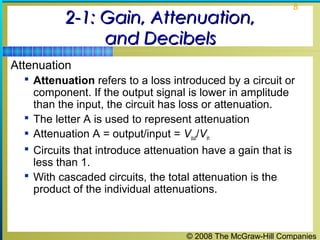
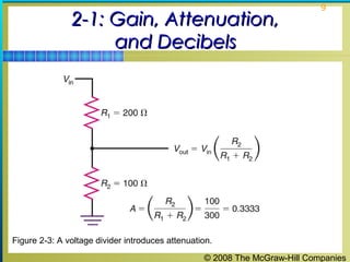
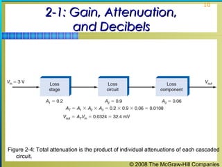
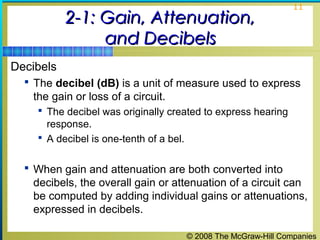
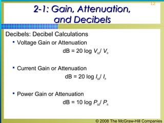
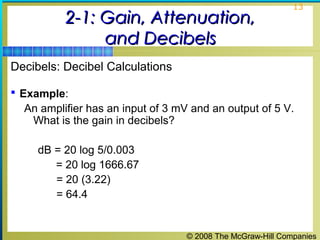
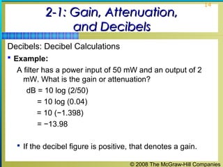
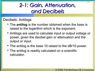
1
Principles of ElectronicPrinciples of Electronic
Communication SystemsCommunication Systems
Third Edition
Louis E. Frenzel, Jr.
© 2008 The McGraw-Hill Companies
2
Chapter 2Chapter 2
The Fundamentals of Electronics: A Review
© 2008 The McGraw-Hill Companies
3
Topics Covered in Chapter 2Topics Covered in Chapter 2
 2-1: Gain, Attenuation, and Decibels
 2-2: Tuned Circuits
 2-3: Filters
 2-4: Fourier Theory
© 2008 The McGraw-Hill Companies
4
2-1: Gain, Attenuation,2-1: Gain, Attenuation,
and Decibelsand Decibels
 Most circuits in electronic communication are used to
manipulate signals to produce a desired result.
 All signal processing circuits involve:
 Gain
 Attenuation
© 2008 The McGraw-Hill Companies
5
2-1: Gain, Attenuation,2-1: Gain, Attenuation,
and Decibelsand Decibels
Gain
 Gain means amplification. It is the ratio of a circuit’s output
to its input.
Figure 2-1: An amplifier has gain.
AV = =
output
input
Vout
Vin
© 2008 The McGraw-Hill Companies
6
2-1: Gain, Attenuation,2-1: Gain, Attenuation,
and Decibelsand Decibels
 Most amplifiers are also power amplifiers, so the same
procedure can be used to calculate power gain AP where Pin
is the power input and Pout is the power output.
Power gain (Ap) = Pout / Pin
 Example:
The power output of an amplifier is 6 watts (W). The power
gain is 80. What is the input power?
Ap = Pout/ Pin therefore Pin = Pout / Ap
Pin = 6 / 80 = 0.075 W = 75 mW
© 2008 The McGraw-Hill Companies
7
2-1: Gain, Attenuation,2-1: Gain, Attenuation,
and Decibelsand Decibels
 An amplifier is cascaded when two or more stages
are connected together.
 The overall gain is the product of the individual circuit
gains.
 Example:
Three cascaded amplifiers have power gains of 5, 2, and 17.
The input power is 40 mW. What is the output power?
Ap = A1 × A2 × A3 = 5 × 2 × 17 = 170
Ap = Pout / Pin therefore Pout = ApPin
Pout = 170 (40 × 10-3
) = 6.8W
© 2008 The McGraw-Hill Companies
8
2-1: Gain, Attenuation,2-1: Gain, Attenuation,
and Decibelsand Decibels
Attenuation
 Attenuation refers to a loss introduced by a circuit or
component. If the output signal is lower in amplitude
than the input, the circuit has loss or attenuation.
 The letter A is used to represent attenuation
 Attenuation A = output/input = Vout/Vin
 Circuits that introduce attenuation have a gain that is
less than 1.
 With cascaded circuits, the total attenuation is the
product of the individual attenuations.
© 2008 The McGraw-Hill Companies
9
2-1: Gain, Attenuation,2-1: Gain, Attenuation,
and Decibelsand Decibels
Figure 2-3: A voltage divider introduces attenuation.
© 2008 The McGraw-Hill Companies
10
2-1: Gain, Attenuation,2-1: Gain, Attenuation,
and Decibelsand Decibels
Figure 2-4: Total attenuation is the product of individual attenuations of each cascaded
circuit.
© 2008 The McGraw-Hill Companies
11
2-1: Gain, Attenuation,2-1: Gain, Attenuation,
and Decibelsand Decibels
Decibels
 The decibel (dB) is a unit of measure used to express
the gain or loss of a circuit.
 The decibel was originally created to express hearing
response.
 A decibel is one-tenth of a bel.
 When gain and attenuation are both converted into
decibels, the overall gain or attenuation of a circuit can
be computed by adding individual gains or attenuations,
expressed in decibels.
© 2008 The McGraw-Hill Companies
12
2-1: Gain, Attenuation,2-1: Gain, Attenuation,
and Decibelsand Decibels
Decibels: Decibel Calculations
 Voltage Gain or Attenuation
dB = 20 log Vout/ Vin
 Current Gain or Attenuation
dB = 20 log Iout/ Iin
 Power Gain or Attenuation
dB = 10 log Pout/ Pin
© 2008 The McGraw-Hill Companies
13
2-1: Gain, Attenuation,2-1: Gain, Attenuation,
and Decibelsand Decibels
Decibels: Decibel Calculations
 Example:
An amplifier has an input of 3 mV and an output of 5 V.
What is the gain in decibels?
dB = 20 log 5/0.003
= 20 log 1666.67
= 20 (3.22)
= 64.4
© 2008 The McGraw-Hill Companies
14
2-1: Gain, Attenuation,2-1: Gain, Attenuation,
and Decibelsand Decibels
Decibels: Decibel Calculations
 Example:
A filter has a power input of 50 mW and an output of 2
mW. What is the gain or attenuation?
dB = 10 log (2/50)
= 10 log (0.04)
= 10 (−1.398)
= −13.98
 If the decibel figure is positive, that denotes a gain.
© 2008 The McGraw-Hill Companies
15
2-1: Gain, Attenuation,2-1: Gain, Attenuation,
and Decibelsand Decibels
Decibels: Antilogs
 The antilog is the number obtained when the base is
raised to the logarithm which is the exponent.
 Antilogs are used to calculate input or output voltage or
power, given the decibel gain or attenuation and the
output or input.
 The antilog is the base 10 raised to the dB/10 power.
 The antilog is readily calculated on a scientific
calculator.
© 2008 The McGraw-Hill Companies
16
2-1: Gain, Attenuation,2-1: Gain, Attenuation,
and Decibelsand Decibels
Decibels: dBm and dBc
 When a decibel value is computed by comparing a
power value to 1 mW, the result is a value called the
dBm. This is a useful reference value.
 The value dBc is a decibel gain attenuation figure
where the reference is the carrier.
© 2008 The McGraw-Hill Companies
17
2-2: Tuned Circuits2-2: Tuned Circuits
 Virtually all communications equipment contains
tuned circuits made up of inductors and capacitors
that resonate at specific frequencies.
© 2008 The McGraw-Hill Companies
18
2-2: Tuned Circuits2-2: Tuned Circuits
Reactive Components
 All tuned circuits and many filters are made up of
inductive and capacitive elements.
 Opposition to alternating-current flow offered by coils
and capacitors is known as reactance.
 Reactance is expressed in ohms (Ω).
© 2008 The McGraw-Hill Companies
19
2-2: Tuned Circuits2-2: Tuned Circuits
Reactive Components: Capacitors
 A capacitor used in an ac circuit charges and
discharges.
 Capacitors tend to oppose voltage changes across
them.
 Opposition to alternating current offered by a capacitor
is known as capacitive reactance (Xc).
 Capacitive reactance (Xc) is inversely proportional to the
value of capacitance (C) and operating frequency (f).
© 2008 The McGraw-Hill Companies
20
2-1: Gain, Attenuation,2-1: Gain, Attenuation,
and Decibelsand Decibels
Reactive Components: Capacitors
 Example:
What is the capacitive reactance of a 100-pF capacitor at
2 MHz?
Xc = 1/2πfC
Xc = 1/6.28 (2 ×10⁶
) (100 × 10−12
)
= 796.2 Ω
© 2008 The McGraw-Hill Companies
21
2-2: Tuned Circuits2-2: Tuned Circuits
Figure 2-8: What a capacitor looks like at high frequencies.
© 2008 The McGraw-Hill Companies
22
2-2: Tuned Circuits2-2: Tuned Circuits
Reactive Components: Inductors
 An inductor, also called a coil or choke, is a winding of
multiple turns of wire.
 When a current is passed through a coil, a magnetic field is
produced around the coil.
 If the applied voltage and current are varying, this causes a
voltage to be self-induced into the coil winding.
 This process has the effect of opposing current changes in
the coil. This effect is known as inductance.
© 2008 The McGraw-Hill Companies
23
2-2: Tuned Circuits2-2: Tuned Circuits
Reactive Components: Inductors
 The basic unit of inductance is the henry (H). However,
practical inductance values are in the millihenry (mH =
10-3
), microhenry (μH = 10-6
), and nanohenry (nH = 10−9
H) regions.
 Opposition to alternating current offered by inductors is
continuous and constant and is known as inductive
reactance (XL).
© 2008 The McGraw-Hill Companies
24
2-2: Tuned Circuits2-2: Tuned Circuits
Figure 2-9: Types of inductors. (a) Heavy self-supporting wire coil. (b) Inductor made
as copper pattern. (c) Insulating form. (d) Toroidal inductor. (e) Ferrite bead inductor.
(f ) Chip inductor.
© 2008 The McGraw-Hill Companies
25
2-2: Tuned Circuits2-2: Tuned Circuits
Reactive Components: Inductors
 Inductive reactance (XL) is directly proportional to
frequency and inductance.
 Example:
What is the inductive reactance of a 40-μH coil at 18
MHz?
XL = 6.28 (18 × 106
) (40 × 10-6
)
= 4522 Ω
© 2008 The McGraw-Hill Companies
26
2-2: Tuned Circuits2-2: Tuned Circuits
Reactive Components: Resistors
 At low frequencies, a standard resistor offers nearly
pure resistance.
 At high frequencies, a resistor’s leads have inductance.
 A resistor’s lead inductance and stray capacitance
cause the resistor to act like a complex RLC circuit.
 Tiny resistor chips used in surface mount circuits
minimize inductance and stray capacitance.
 Film resistors minimize thermal effect noise.
© 2008 The McGraw-Hill Companies
27
2-2: Tuned Circuits2-2: Tuned Circuits
Figure 2-11: Equivalent circuit of a resistor at high (radio) frequencies.
© 2008 The McGraw-Hill Companies
28
2-2: Tuned Circuits2-2: Tuned Circuits
Reactive Components: Skin Effect.
 Skin effect is the tendency of electrons flowing in a
conductor to flow near and on the outer surface of the
conductor frequencies in the VHF, UHF, and microwave
regions.
 This process increases the resistance of the conductor
and greatly affects the performance of the circuit.
© 2008 The McGraw-Hill Companies
29
2-2: Tuned Circuits2-2: Tuned Circuits
Figure 2-12: Skin effect increases wire and inductor resistance at high frequencies.
© 2008 The McGraw-Hill Companies
30
2-2: Tuned Circuits2-2: Tuned Circuits
Tuned Circuits and Resonance
 A tuned circuit is made up of inductance and
capacitance and resonates at a specific frequency, the
resonant frequency.
 The terms tuned circuit and resonant circuit are used
interchangeably.
 Tuned circuits are frequency-selective and respond best
at their resonant frequency.
© 2008 The McGraw-Hill Companies
31
2-2: Tuned Circuits2-2: Tuned Circuits
Tuned Circuits and Resonance: Series Resonant Circuits
 A series resonant circuit is made up of inductance,
capacitance and resistance connected in series.
 Series resonant circuits are often referred to as LCR or
RLC circuits.
 Resonance occurs when inductive and capacitive
reactances are equal.
 Resonant frequency (fr) is inversely proportional to
inductance and capacitance.
fr =
1
2π√LC
© 2008 The McGraw-Hill Companies
32
2-2: Tuned Circuits2-2: Tuned Circuits
Figure 2-13: Series RLC circuit.
Figure 2-14 Variation of reactance with frequency.
© 2008 The McGraw-Hill Companies
33
2-2: Tuned Circuits2-2: Tuned Circuits
Tuned Circuits and Resonance: Series Resonant
Circuits
 Example:
What is the resonant frequency of a 2.7-pF capacitor and
a 33-nH inductor?
fr = 1/2π√LC
= 1/6.28√33 × 10−9
× 2.7 × 10−12
fr = 5.33 × 10⁸
Hz or 533 MHz
© 2008 The McGraw-Hill Companies
34
2-2: Tuned Circuits2-2: Tuned Circuits
Tuned Circuits and Resonance: Series Resonant Circuits
 The bandwidth (BW) of a series resonant circuit is the
narrow frequency range over which the current is highest.
 Half-power points are the current levels at which the
frequency response is 70.7% of the peak value of
resonance.
 The quality (Q) of a series resonant circuit is the ratio of
the inductive reactance to the total circuit resistance.
 Selectivity is how a circuit responds to varying
frequencies.
 The bandwidth of a circuit is inversely proportional to Q.
© 2008 The McGraw-Hill Companies
35
2-2: Tuned Circuits2-2: Tuned Circuits
Figure 2-16: Bandwidth of a series resonant circuit.
© 2008 The McGraw-Hill Companies
36
2-2: Tuned Circuits2-2: Tuned Circuits
Figure 2-17: The effect of Q on bandwidth and selectivity in a resonant circuit.
© 2008 The McGraw-Hill Companies
37
2-2: Tuned Circuits2-2: Tuned Circuits
Tuned Circuits and Resonance: Parallel Resonant
Circuits
 A parallel resonant circuit is formed when the inductor
and capacitor of a tuned circuit are connected in parallel
with the applied voltage.
 A parallel resonant circuit is often referred to as a LCR or
RLC circuit.
 Resonance occurs when inductive and capacitive
reactances are equal.
 The resonant frequency (fr) is inversely proportional to
inductance and capacitance.
© 2008 The McGraw-Hill Companies
38
2-2: Tuned Circuits2-2: Tuned Circuits
Figure 2-19: Parallel resonant circuit currents. (a) Parallel resonant circuit. (b) Current
relationships in parallel resonant circuit.
© 2008 The McGraw-Hill Companies
39
2-2: Tuned Circuits2-2: Tuned Circuits
Tuned Circuits and Resonance: Parallel Resonant
Circuits
 At resonance, a parallel tuned circuit appears to
 have infinite resistance
 draw no current from the source
 have infinite impedance
 act as an open circuit.
 However, there is a high circulating current between the
inductor and capacitor, storing and transferring energy
between them.
© 2008 The McGraw-Hill Companies
40
2-2: Tuned Circuits2-2: Tuned Circuits
Tuned Circuits and Resonance: Parallel Resonant
Circuit
 Because such a circuit acts as a kind of storage vessel
for electric energy, it is often referred to as a tank
circuit and the circulating current is referred to as the
tank current.
© 2008 The McGraw-Hill Companies
41
2-3: Filters2-3: Filters
 A filter is a frequency-selective circuit.
 Filters pass certain frequencies and reject others.
 Passive filters are created using components such
as: resistors, capacitors, and inductors that do not
amplify.
 Active filters use amplifying devices such as
transistors and operational amplifiers.
© 2008 The McGraw-Hill Companies
42
2-3: Filters2-3: Filters
 There are five basic kinds of filter circuits:
 Low-pass filters only pass frequencies below a critical
(cutoff) frequency.
 High-pass filters only pass frequencies above the
cutoff frequency.
 Bandpass filters pass frequencies over a narrow range
between lower and upper cutoff frequencies.
 Band-reject filters reject or stop frequencies over a
narrow range between lower and upper cutoff
frequencies.
 All-pass filters pass all frequencies over a desired
range but have a predictable phase shift characteristic.
© 2008 The McGraw-Hill Companies
43
2-3: Filters2-3: Filters
RC Filters
 RC filters use combinations of resistors and capacitors
to achieve a desired frequency response.
 Most RC filters are of the low-pass or high-pass type.
 Any low-pass or high-pass filter is effectively a
frequency-dependent voltage divider.
 An RC coupling circuit is a high-pass filter because the
ac input component is developed across the resistor
while dc voltage is blocked by a capacitor.
© 2008 The McGraw-Hill Companies
44
2-3: Filters2-3: Filters
RC Filters: Low-Pass Filter
 A low-pass filter is a circuit that introduces no
attenuation at frequencies below the cutoff frequency
but completely eliminates all signals with frequencies
above the cutoff.
 Low-pass filters are sometimes referred to as high cut
filters.
 The cutoff frequency of a filter is that point where the
resistance (R) and capacitive reactance (XC) are equal.
© 2008 The McGraw-Hill Companies
45
2-3: Filters2-3: Filters
Figure 2-24: RC low-pass filter. (a) Circuit. (b) Low-pass filter.
© 2008 The McGraw-Hill Companies
46
2-3: Filters2-3: Filters
RC Filters: High-Pass Filter
 A high-pass filter passes frequencies above the cutoff
frequency with little or no attenuation but greatly
attenuates those signals below the cutoff.
 The basic high-pass filter is a voltage divider with the
capacitor serving as the frequency-sensitive
component.
 A high-pass filter can be implemented with a coil and a
resistor.
© 2008 The McGraw-Hill Companies
47
2-3: Filters2-3: Filters
Figure 2-28: (a) RC high-pass filter. (b) RL high-pass filter.
© 2008 The McGraw-Hill Companies
48
2-3: Filters2-3: Filters
RC Filters: RC Notch Filter
 Notch filters, also called bandstop or band-reject
filters, attenuate a narrow range of frequencies around
a center point (frequency).
 A simple notch filter implemented with resistors and
capacitors is called a parallel-T or twin-T filter.
 The center notch frequency is calculated:
fnotch =
1
2πRC
© 2008 The McGraw-Hill Companies
49
2-3: Filters2-3: Filters
Figure 2-29: RC notch filter.
© 2008 The McGraw-Hill Companies
50
2-3: Filters2-3: Filters
LC Filters
 LC filters use combinations of inductors and capacitors
to achieve a desired frequency response.
 They are typically used with radio frequency (RF)
applications.
© 2008 The McGraw-Hill Companies
51
2-3: Filters2-3: Filters
LC Filters
 Passband is the frequency range over which the filter
passes signals.
 Stop band is the range of frequencies outside the
passband; that is, the range of frequencies that is
greatly attenuated by the filter.
 Attenuation is the amount by which undesired
frequencies in the stop band are reduced.
© 2008 The McGraw-Hill Companies
52
2-3: Filters2-3: Filters
LC Filters
 Insertion loss is the loss the filter introduces to the
signals in the passband.
 Impedance is the resistive value of the load and source
terminations of the filter.
 Ripple is a term used to describe the amplitude
variation with frequency in the passband.
 Shape factor is the ratio of the stop bandwidth to the
pass bandwidth of a bandpass filter.
© 2008 The McGraw-Hill Companies
53
2-3: Filters2-3: Filters
LC Filters
 A pole is a frequency at which there is a high
impedance in the circuit.
 Zero is a term used to refer to a frequency at which
there is zero impedance in the circuit.
 Envelope delay or time delay is the time it takes for a
specific point on an input waveform to pass through the
filter.
 Roll-off or attenuation rate is the rate of change of
amplitude with frequency in a filter.
© 2008 The McGraw-Hill Companies
54
2-3: Filters2-3: Filters
Types of Filters
 The most widely used LC filters are named after the
people who discovered them and developed the
analysis and design method for each.
 Butterworth: The Butterworth filter effect has
maximum flatness in response in the passband and a
uniform attenuation with frequency.
 Chebyshev: Has extremely good selectivity, and
attenuation just outside the passband is very high,
but has ripple in the passband.
© 2008 The McGraw-Hill Companies
55
2-3: Filters2-3: Filters
Types of Filters
 Cauer (Elliptical): Produces greater attenuation out of
the passband, but with higher ripple within and
outside of the passband.
 Bessel (Thomson): Provides the desired frequency
response (i.e., low-pass, bandpass, etc.) but has a
constant time delay in the passband.
© 2008 The McGraw-Hill Companies
56
2-3: Filters2-3: Filters
Figure 2-34: Butterworth, elliptical, Bessel, and Chebyshev response curves.
© 2008 The McGraw-Hill Companies
57
2-3: Filters2-3: Filters
Types of Filters: Mechanical and Bandpass Filters
 A mechanical filter uses resonant vibrations of
mechanical disks to provide the selectivity.
 Bandpass filters, configured with series or parallel
resonant circuits, allow a narrow range of frequencies
around a center frequency to pass with minimum
attenuation but rejects frequencies above and below
this range.
© 2008 The McGraw-Hill Companies
58
2-3: Filters2-3: Filters
Figure 2-36: Simple bandpass filters.
© 2008 The McGraw-Hill Companies
59
2-3: Filters2-3: Filters
Types of Filters: Band-Reject Filters
 Band-reject filters reject a narrow band of frequencies
around a center or notch frequency.
 Band-reject filters are also known as bandstop filters or
traps.
© 2008 The McGraw-Hill Companies
60
2-3: Filters2-3: Filters
Figure 2-39: LC tuned bandstop filters. (a) Shunt. (b) Series. (c) Response curve.
© 2008 The McGraw-Hill Companies
61
2-3: Filters2-3: Filters
Active Filters
 Active filters are frequency-selective circuits that
incorporate RC networks and amplifiers with feedback
to produce low-pass, high-pass, bandpass, and
bandstop performance. Advantages are:
 Gain
 No inductors
 Easy to tune
 Isolation
 Easier impedance matching
© 2008 The McGraw-Hill Companies
62
2-3: Filters2-3: Filters
Active Filters
 A special form of active filter is the variable-state filter,
which can simultaneously provide low-pass, high-pass,
and bandpass operation from one circuit.
© 2008 The McGraw-Hill Companies
63
2-3: Filters2-3: Filters
Crystal and Ceramic Filters
 Crystal and ceramic filters are made of thin slivers of
quartz crystal or certain other types of ceramic
materials.
 Crystals and ceramic elements are widely used in
oscillators to set frequency of operation to a precise
value.
 Crystals and ceramic elements are also used as circuit
elements to form filters, specifically bandpass filters.
© 2008 The McGraw-Hill Companies
64
2-3: Filters2-3: Filters
Figure 2-46: Quartz crystal. (a) Equivalent circuit. (b) Schematic symbol.
© 2008 The McGraw-Hill Companies
65
2-3: Filters2-3: Filters
Figure 2-50: Schematic symbol for a ceramic filter.
© 2008 The McGraw-Hill Companies
66
2-3: Filters2-3: Filters
Crystal and Ceramic Filters: Surface Acoustic Wave
Filters
 The surface acoustic wave (SAW) filter is a special
form of a crystal filter designed to provide the exact
selectivity required by a given application.
 SAW filters are normally used at very high radio
frequencies where selectivity is difficult to obtain.
 They are widely used in modern TV receivers, radar
receivers, wireless LANs, and cell phones.
© 2008 The McGraw-Hill Companies
67
2-3: Filters2-3: Filters
Figure 2-51: A surface acoustic wave filter.
© 2008 The McGraw-Hill Companies
68
2-3: Filters2-3: Filters
Switched Capacitor Filters
 Switched capacitor filters (SCFs), also known as
analog sampled data filters or commutating filters,
are active IC filters made of op amps, capacitors, and
transistor switches.
 They provide a way to make tuned or selective circuits
in an IC without the use of discrete inductors,
capacitors, or resistors.
 The secret to the SCF is that all resistors are replaced
by capacitors that are switched by MOSFET switches.
© 2008 The McGraw-Hill Companies
69
2-3: Filters2-3: Filters
Figure 2-52: IC integrators. (a) Conventional integrator. (b) Switched capacitor
integrator.
© 2008 The McGraw-Hill Companies
70
2-3: Filters2-3: Filters
Figure 2-53: A commutating SCF.
© 2008 The McGraw-Hill Companies
71
2-4: Fourier Theory2-4: Fourier Theory
 One method used to determine the characteristics and
performance of a communication circuit or system,
specifically for non-sine wave approach, is Fourier
analysis.
 The Fourier theory states that a nonsinusoidal
waveform can be broken down into individual
harmonically related sine wave or cosine wave
components.
 A square wave is one classic example of this
phenomenon.
© 2008 The McGraw-Hill Companies
72
2-4: Fourier Theory2-4: Fourier Theory
Figure 2-57: A sine wave and its harmonics.
© 2008 The McGraw-Hill Companies
73
2-4: Fourier Theory2-4: Fourier Theory
Figure 2-58: A square wave.
© 2008 The McGraw-Hill Companies
74
2-4: Fourier Theory2-4: Fourier Theory
Basic Concepts
 Fourier analysis states that a square wave is made up
of a sine wave at the fundamental frequency of the
square wave plus an infinite number of odd harmonics.
 Fourier analysis allows us to determine not only sine-
wave components in a complex signal but also a
signal’s bandwidth.
© 2008 The McGraw-Hill Companies
75
2-4: Fourier Theory2-4: Fourier Theory
Time Domain Versus Frequency Domain
 Analysis of variations of voltage, current, or power with
respect to time are expressed in the time domain.
 A frequency domain plots amplitude variations with
respect to frequency.
 Fourier theory gives us a new and different way to
express and illustrate complex signals, that is, with
respect to frequency.
© 2008 The McGraw-Hill Companies
76
2-4: Fourier Theory2-4: Fourier Theory
Figure 2-63: The relationship between time and frequency domains.
© 2008 The McGraw-Hill Companies
77
2-4: Fourier Theory2-4: Fourier Theory
Figure 2-61: Common nonsinusoidal waves and their Fourier equations. (e) Full
cosine wave.
© 2008 The McGraw-Hill Companies
78
2-4: Fourier Theory2-4: Fourier Theory
Time Domain Versus Frequency Domain
 A spectrum analyzer is an instrument used to produce
a frequency-domain display.
 It is the key test instrument in designing, analyzing, and
troubleshooting communication equipment.

Chapter02

  • 1.
    1 Principles of ElectronicPrinciplesof Electronic Communication SystemsCommunication Systems Third Edition Louis E. Frenzel, Jr. © 2008 The McGraw-Hill Companies
  • 2.
    2 Chapter 2Chapter 2 TheFundamentals of Electronics: A Review
  • 3.
    © 2008 TheMcGraw-Hill Companies 3 Topics Covered in Chapter 2Topics Covered in Chapter 2  2-1: Gain, Attenuation, and Decibels  2-2: Tuned Circuits  2-3: Filters  2-4: Fourier Theory
  • 4.
    © 2008 TheMcGraw-Hill Companies 4 2-1: Gain, Attenuation,2-1: Gain, Attenuation, and Decibelsand Decibels  Most circuits in electronic communication are used to manipulate signals to produce a desired result.  All signal processing circuits involve:  Gain  Attenuation
  • 5.
    © 2008 TheMcGraw-Hill Companies 5 2-1: Gain, Attenuation,2-1: Gain, Attenuation, and Decibelsand Decibels Gain  Gain means amplification. It is the ratio of a circuit’s output to its input. Figure 2-1: An amplifier has gain. AV = = output input Vout Vin
  • 6.
    © 2008 TheMcGraw-Hill Companies 6 2-1: Gain, Attenuation,2-1: Gain, Attenuation, and Decibelsand Decibels  Most amplifiers are also power amplifiers, so the same procedure can be used to calculate power gain AP where Pin is the power input and Pout is the power output. Power gain (Ap) = Pout / Pin  Example: The power output of an amplifier is 6 watts (W). The power gain is 80. What is the input power? Ap = Pout/ Pin therefore Pin = Pout / Ap Pin = 6 / 80 = 0.075 W = 75 mW
  • 7.
    © 2008 TheMcGraw-Hill Companies 7 2-1: Gain, Attenuation,2-1: Gain, Attenuation, and Decibelsand Decibels  An amplifier is cascaded when two or more stages are connected together.  The overall gain is the product of the individual circuit gains.  Example: Three cascaded amplifiers have power gains of 5, 2, and 17. The input power is 40 mW. What is the output power? Ap = A1 × A2 × A3 = 5 × 2 × 17 = 170 Ap = Pout / Pin therefore Pout = ApPin Pout = 170 (40 × 10-3 ) = 6.8W
  • 8.
    © 2008 TheMcGraw-Hill Companies 8 2-1: Gain, Attenuation,2-1: Gain, Attenuation, and Decibelsand Decibels Attenuation  Attenuation refers to a loss introduced by a circuit or component. If the output signal is lower in amplitude than the input, the circuit has loss or attenuation.  The letter A is used to represent attenuation  Attenuation A = output/input = Vout/Vin  Circuits that introduce attenuation have a gain that is less than 1.  With cascaded circuits, the total attenuation is the product of the individual attenuations.
  • 9.
    © 2008 TheMcGraw-Hill Companies 9 2-1: Gain, Attenuation,2-1: Gain, Attenuation, and Decibelsand Decibels Figure 2-3: A voltage divider introduces attenuation.
  • 10.
    © 2008 TheMcGraw-Hill Companies 10 2-1: Gain, Attenuation,2-1: Gain, Attenuation, and Decibelsand Decibels Figure 2-4: Total attenuation is the product of individual attenuations of each cascaded circuit.
  • 11.
    © 2008 TheMcGraw-Hill Companies 11 2-1: Gain, Attenuation,2-1: Gain, Attenuation, and Decibelsand Decibels Decibels  The decibel (dB) is a unit of measure used to express the gain or loss of a circuit.  The decibel was originally created to express hearing response.  A decibel is one-tenth of a bel.  When gain and attenuation are both converted into decibels, the overall gain or attenuation of a circuit can be computed by adding individual gains or attenuations, expressed in decibels.
  • 12.
    © 2008 TheMcGraw-Hill Companies 12 2-1: Gain, Attenuation,2-1: Gain, Attenuation, and Decibelsand Decibels Decibels: Decibel Calculations  Voltage Gain or Attenuation dB = 20 log Vout/ Vin  Current Gain or Attenuation dB = 20 log Iout/ Iin  Power Gain or Attenuation dB = 10 log Pout/ Pin
  • 13.
    © 2008 TheMcGraw-Hill Companies 13 2-1: Gain, Attenuation,2-1: Gain, Attenuation, and Decibelsand Decibels Decibels: Decibel Calculations  Example: An amplifier has an input of 3 mV and an output of 5 V. What is the gain in decibels? dB = 20 log 5/0.003 = 20 log 1666.67 = 20 (3.22) = 64.4
  • 14.
    © 2008 TheMcGraw-Hill Companies 14 2-1: Gain, Attenuation,2-1: Gain, Attenuation, and Decibelsand Decibels Decibels: Decibel Calculations  Example: A filter has a power input of 50 mW and an output of 2 mW. What is the gain or attenuation? dB = 10 log (2/50) = 10 log (0.04) = 10 (−1.398) = −13.98  If the decibel figure is positive, that denotes a gain.
  • 15.
    © 2008 TheMcGraw-Hill Companies 15 2-1: Gain, Attenuation,2-1: Gain, Attenuation, and Decibelsand Decibels Decibels: Antilogs  The antilog is the number obtained when the base is raised to the logarithm which is the exponent.  Antilogs are used to calculate input or output voltage or power, given the decibel gain or attenuation and the output or input.  The antilog is the base 10 raised to the dB/10 power.  The antilog is readily calculated on a scientific calculator.
  • 16.
    © 2008 TheMcGraw-Hill Companies 16 2-1: Gain, Attenuation,2-1: Gain, Attenuation, and Decibelsand Decibels Decibels: dBm and dBc  When a decibel value is computed by comparing a power value to 1 mW, the result is a value called the dBm. This is a useful reference value.  The value dBc is a decibel gain attenuation figure where the reference is the carrier.
  • 17.
    © 2008 TheMcGraw-Hill Companies 17 2-2: Tuned Circuits2-2: Tuned Circuits  Virtually all communications equipment contains tuned circuits made up of inductors and capacitors that resonate at specific frequencies.
  • 18.
    © 2008 TheMcGraw-Hill Companies 18 2-2: Tuned Circuits2-2: Tuned Circuits Reactive Components  All tuned circuits and many filters are made up of inductive and capacitive elements.  Opposition to alternating-current flow offered by coils and capacitors is known as reactance.  Reactance is expressed in ohms (Ω).
  • 19.
    © 2008 TheMcGraw-Hill Companies 19 2-2: Tuned Circuits2-2: Tuned Circuits Reactive Components: Capacitors  A capacitor used in an ac circuit charges and discharges.  Capacitors tend to oppose voltage changes across them.  Opposition to alternating current offered by a capacitor is known as capacitive reactance (Xc).  Capacitive reactance (Xc) is inversely proportional to the value of capacitance (C) and operating frequency (f).
  • 20.
    © 2008 TheMcGraw-Hill Companies 20 2-1: Gain, Attenuation,2-1: Gain, Attenuation, and Decibelsand Decibels Reactive Components: Capacitors  Example: What is the capacitive reactance of a 100-pF capacitor at 2 MHz? Xc = 1/2πfC Xc = 1/6.28 (2 ×10⁶ ) (100 × 10−12 ) = 796.2 Ω
  • 21.
    © 2008 TheMcGraw-Hill Companies 21 2-2: Tuned Circuits2-2: Tuned Circuits Figure 2-8: What a capacitor looks like at high frequencies.
  • 22.
    © 2008 TheMcGraw-Hill Companies 22 2-2: Tuned Circuits2-2: Tuned Circuits Reactive Components: Inductors  An inductor, also called a coil or choke, is a winding of multiple turns of wire.  When a current is passed through a coil, a magnetic field is produced around the coil.  If the applied voltage and current are varying, this causes a voltage to be self-induced into the coil winding.  This process has the effect of opposing current changes in the coil. This effect is known as inductance.
  • 23.
    © 2008 TheMcGraw-Hill Companies 23 2-2: Tuned Circuits2-2: Tuned Circuits Reactive Components: Inductors  The basic unit of inductance is the henry (H). However, practical inductance values are in the millihenry (mH = 10-3 ), microhenry (μH = 10-6 ), and nanohenry (nH = 10−9 H) regions.  Opposition to alternating current offered by inductors is continuous and constant and is known as inductive reactance (XL).
  • 24.
    © 2008 TheMcGraw-Hill Companies 24 2-2: Tuned Circuits2-2: Tuned Circuits Figure 2-9: Types of inductors. (a) Heavy self-supporting wire coil. (b) Inductor made as copper pattern. (c) Insulating form. (d) Toroidal inductor. (e) Ferrite bead inductor. (f ) Chip inductor.
  • 25.
    © 2008 TheMcGraw-Hill Companies 25 2-2: Tuned Circuits2-2: Tuned Circuits Reactive Components: Inductors  Inductive reactance (XL) is directly proportional to frequency and inductance.  Example: What is the inductive reactance of a 40-μH coil at 18 MHz? XL = 6.28 (18 × 106 ) (40 × 10-6 ) = 4522 Ω
  • 26.
    © 2008 TheMcGraw-Hill Companies 26 2-2: Tuned Circuits2-2: Tuned Circuits Reactive Components: Resistors  At low frequencies, a standard resistor offers nearly pure resistance.  At high frequencies, a resistor’s leads have inductance.  A resistor’s lead inductance and stray capacitance cause the resistor to act like a complex RLC circuit.  Tiny resistor chips used in surface mount circuits minimize inductance and stray capacitance.  Film resistors minimize thermal effect noise.
  • 27.
    © 2008 TheMcGraw-Hill Companies 27 2-2: Tuned Circuits2-2: Tuned Circuits Figure 2-11: Equivalent circuit of a resistor at high (radio) frequencies.
  • 28.
    © 2008 TheMcGraw-Hill Companies 28 2-2: Tuned Circuits2-2: Tuned Circuits Reactive Components: Skin Effect.  Skin effect is the tendency of electrons flowing in a conductor to flow near and on the outer surface of the conductor frequencies in the VHF, UHF, and microwave regions.  This process increases the resistance of the conductor and greatly affects the performance of the circuit.
  • 29.
    © 2008 TheMcGraw-Hill Companies 29 2-2: Tuned Circuits2-2: Tuned Circuits Figure 2-12: Skin effect increases wire and inductor resistance at high frequencies.
  • 30.
    © 2008 TheMcGraw-Hill Companies 30 2-2: Tuned Circuits2-2: Tuned Circuits Tuned Circuits and Resonance  A tuned circuit is made up of inductance and capacitance and resonates at a specific frequency, the resonant frequency.  The terms tuned circuit and resonant circuit are used interchangeably.  Tuned circuits are frequency-selective and respond best at their resonant frequency.
  • 31.
    © 2008 TheMcGraw-Hill Companies 31 2-2: Tuned Circuits2-2: Tuned Circuits Tuned Circuits and Resonance: Series Resonant Circuits  A series resonant circuit is made up of inductance, capacitance and resistance connected in series.  Series resonant circuits are often referred to as LCR or RLC circuits.  Resonance occurs when inductive and capacitive reactances are equal.  Resonant frequency (fr) is inversely proportional to inductance and capacitance. fr = 1 2π√LC
  • 32.
    © 2008 TheMcGraw-Hill Companies 32 2-2: Tuned Circuits2-2: Tuned Circuits Figure 2-13: Series RLC circuit. Figure 2-14 Variation of reactance with frequency.
  • 33.
    © 2008 TheMcGraw-Hill Companies 33 2-2: Tuned Circuits2-2: Tuned Circuits Tuned Circuits and Resonance: Series Resonant Circuits  Example: What is the resonant frequency of a 2.7-pF capacitor and a 33-nH inductor? fr = 1/2π√LC = 1/6.28√33 × 10−9 × 2.7 × 10−12 fr = 5.33 × 10⁸ Hz or 533 MHz
  • 34.
    © 2008 TheMcGraw-Hill Companies 34 2-2: Tuned Circuits2-2: Tuned Circuits Tuned Circuits and Resonance: Series Resonant Circuits  The bandwidth (BW) of a series resonant circuit is the narrow frequency range over which the current is highest.  Half-power points are the current levels at which the frequency response is 70.7% of the peak value of resonance.  The quality (Q) of a series resonant circuit is the ratio of the inductive reactance to the total circuit resistance.  Selectivity is how a circuit responds to varying frequencies.  The bandwidth of a circuit is inversely proportional to Q.
  • 35.
    © 2008 TheMcGraw-Hill Companies 35 2-2: Tuned Circuits2-2: Tuned Circuits Figure 2-16: Bandwidth of a series resonant circuit.
  • 36.
    © 2008 TheMcGraw-Hill Companies 36 2-2: Tuned Circuits2-2: Tuned Circuits Figure 2-17: The effect of Q on bandwidth and selectivity in a resonant circuit.
  • 37.
    © 2008 TheMcGraw-Hill Companies 37 2-2: Tuned Circuits2-2: Tuned Circuits Tuned Circuits and Resonance: Parallel Resonant Circuits  A parallel resonant circuit is formed when the inductor and capacitor of a tuned circuit are connected in parallel with the applied voltage.  A parallel resonant circuit is often referred to as a LCR or RLC circuit.  Resonance occurs when inductive and capacitive reactances are equal.  The resonant frequency (fr) is inversely proportional to inductance and capacitance.
  • 38.
    © 2008 TheMcGraw-Hill Companies 38 2-2: Tuned Circuits2-2: Tuned Circuits Figure 2-19: Parallel resonant circuit currents. (a) Parallel resonant circuit. (b) Current relationships in parallel resonant circuit.
  • 39.
    © 2008 TheMcGraw-Hill Companies 39 2-2: Tuned Circuits2-2: Tuned Circuits Tuned Circuits and Resonance: Parallel Resonant Circuits  At resonance, a parallel tuned circuit appears to  have infinite resistance  draw no current from the source  have infinite impedance  act as an open circuit.  However, there is a high circulating current between the inductor and capacitor, storing and transferring energy between them.
  • 40.
    © 2008 TheMcGraw-Hill Companies 40 2-2: Tuned Circuits2-2: Tuned Circuits Tuned Circuits and Resonance: Parallel Resonant Circuit  Because such a circuit acts as a kind of storage vessel for electric energy, it is often referred to as a tank circuit and the circulating current is referred to as the tank current.
  • 41.
    © 2008 TheMcGraw-Hill Companies 41 2-3: Filters2-3: Filters  A filter is a frequency-selective circuit.  Filters pass certain frequencies and reject others.  Passive filters are created using components such as: resistors, capacitors, and inductors that do not amplify.  Active filters use amplifying devices such as transistors and operational amplifiers.
  • 42.
    © 2008 TheMcGraw-Hill Companies 42 2-3: Filters2-3: Filters  There are five basic kinds of filter circuits:  Low-pass filters only pass frequencies below a critical (cutoff) frequency.  High-pass filters only pass frequencies above the cutoff frequency.  Bandpass filters pass frequencies over a narrow range between lower and upper cutoff frequencies.  Band-reject filters reject or stop frequencies over a narrow range between lower and upper cutoff frequencies.  All-pass filters pass all frequencies over a desired range but have a predictable phase shift characteristic.
  • 43.
    © 2008 TheMcGraw-Hill Companies 43 2-3: Filters2-3: Filters RC Filters  RC filters use combinations of resistors and capacitors to achieve a desired frequency response.  Most RC filters are of the low-pass or high-pass type.  Any low-pass or high-pass filter is effectively a frequency-dependent voltage divider.  An RC coupling circuit is a high-pass filter because the ac input component is developed across the resistor while dc voltage is blocked by a capacitor.
  • 44.
    © 2008 TheMcGraw-Hill Companies 44 2-3: Filters2-3: Filters RC Filters: Low-Pass Filter  A low-pass filter is a circuit that introduces no attenuation at frequencies below the cutoff frequency but completely eliminates all signals with frequencies above the cutoff.  Low-pass filters are sometimes referred to as high cut filters.  The cutoff frequency of a filter is that point where the resistance (R) and capacitive reactance (XC) are equal.
  • 45.
    © 2008 TheMcGraw-Hill Companies 45 2-3: Filters2-3: Filters Figure 2-24: RC low-pass filter. (a) Circuit. (b) Low-pass filter.
  • 46.
    © 2008 TheMcGraw-Hill Companies 46 2-3: Filters2-3: Filters RC Filters: High-Pass Filter  A high-pass filter passes frequencies above the cutoff frequency with little or no attenuation but greatly attenuates those signals below the cutoff.  The basic high-pass filter is a voltage divider with the capacitor serving as the frequency-sensitive component.  A high-pass filter can be implemented with a coil and a resistor.
  • 47.
    © 2008 TheMcGraw-Hill Companies 47 2-3: Filters2-3: Filters Figure 2-28: (a) RC high-pass filter. (b) RL high-pass filter.
  • 48.
    © 2008 TheMcGraw-Hill Companies 48 2-3: Filters2-3: Filters RC Filters: RC Notch Filter  Notch filters, also called bandstop or band-reject filters, attenuate a narrow range of frequencies around a center point (frequency).  A simple notch filter implemented with resistors and capacitors is called a parallel-T or twin-T filter.  The center notch frequency is calculated: fnotch = 1 2πRC
  • 49.
    © 2008 TheMcGraw-Hill Companies 49 2-3: Filters2-3: Filters Figure 2-29: RC notch filter.
  • 50.
    © 2008 TheMcGraw-Hill Companies 50 2-3: Filters2-3: Filters LC Filters  LC filters use combinations of inductors and capacitors to achieve a desired frequency response.  They are typically used with radio frequency (RF) applications.
  • 51.
    © 2008 TheMcGraw-Hill Companies 51 2-3: Filters2-3: Filters LC Filters  Passband is the frequency range over which the filter passes signals.  Stop band is the range of frequencies outside the passband; that is, the range of frequencies that is greatly attenuated by the filter.  Attenuation is the amount by which undesired frequencies in the stop band are reduced.
  • 52.
    © 2008 TheMcGraw-Hill Companies 52 2-3: Filters2-3: Filters LC Filters  Insertion loss is the loss the filter introduces to the signals in the passband.  Impedance is the resistive value of the load and source terminations of the filter.  Ripple is a term used to describe the amplitude variation with frequency in the passband.  Shape factor is the ratio of the stop bandwidth to the pass bandwidth of a bandpass filter.
  • 53.
    © 2008 TheMcGraw-Hill Companies 53 2-3: Filters2-3: Filters LC Filters  A pole is a frequency at which there is a high impedance in the circuit.  Zero is a term used to refer to a frequency at which there is zero impedance in the circuit.  Envelope delay or time delay is the time it takes for a specific point on an input waveform to pass through the filter.  Roll-off or attenuation rate is the rate of change of amplitude with frequency in a filter.
  • 54.
    © 2008 TheMcGraw-Hill Companies 54 2-3: Filters2-3: Filters Types of Filters  The most widely used LC filters are named after the people who discovered them and developed the analysis and design method for each.  Butterworth: The Butterworth filter effect has maximum flatness in response in the passband and a uniform attenuation with frequency.  Chebyshev: Has extremely good selectivity, and attenuation just outside the passband is very high, but has ripple in the passband.
  • 55.
    © 2008 TheMcGraw-Hill Companies 55 2-3: Filters2-3: Filters Types of Filters  Cauer (Elliptical): Produces greater attenuation out of the passband, but with higher ripple within and outside of the passband.  Bessel (Thomson): Provides the desired frequency response (i.e., low-pass, bandpass, etc.) but has a constant time delay in the passband.
  • 56.
    © 2008 TheMcGraw-Hill Companies 56 2-3: Filters2-3: Filters Figure 2-34: Butterworth, elliptical, Bessel, and Chebyshev response curves.
  • 57.
    © 2008 TheMcGraw-Hill Companies 57 2-3: Filters2-3: Filters Types of Filters: Mechanical and Bandpass Filters  A mechanical filter uses resonant vibrations of mechanical disks to provide the selectivity.  Bandpass filters, configured with series or parallel resonant circuits, allow a narrow range of frequencies around a center frequency to pass with minimum attenuation but rejects frequencies above and below this range.
  • 58.
    © 2008 TheMcGraw-Hill Companies 58 2-3: Filters2-3: Filters Figure 2-36: Simple bandpass filters.
  • 59.
    © 2008 TheMcGraw-Hill Companies 59 2-3: Filters2-3: Filters Types of Filters: Band-Reject Filters  Band-reject filters reject a narrow band of frequencies around a center or notch frequency.  Band-reject filters are also known as bandstop filters or traps.
  • 60.
    © 2008 TheMcGraw-Hill Companies 60 2-3: Filters2-3: Filters Figure 2-39: LC tuned bandstop filters. (a) Shunt. (b) Series. (c) Response curve.
  • 61.
    © 2008 TheMcGraw-Hill Companies 61 2-3: Filters2-3: Filters Active Filters  Active filters are frequency-selective circuits that incorporate RC networks and amplifiers with feedback to produce low-pass, high-pass, bandpass, and bandstop performance. Advantages are:  Gain  No inductors  Easy to tune  Isolation  Easier impedance matching
  • 62.
    © 2008 TheMcGraw-Hill Companies 62 2-3: Filters2-3: Filters Active Filters  A special form of active filter is the variable-state filter, which can simultaneously provide low-pass, high-pass, and bandpass operation from one circuit.
  • 63.
    © 2008 TheMcGraw-Hill Companies 63 2-3: Filters2-3: Filters Crystal and Ceramic Filters  Crystal and ceramic filters are made of thin slivers of quartz crystal or certain other types of ceramic materials.  Crystals and ceramic elements are widely used in oscillators to set frequency of operation to a precise value.  Crystals and ceramic elements are also used as circuit elements to form filters, specifically bandpass filters.
  • 64.
    © 2008 TheMcGraw-Hill Companies 64 2-3: Filters2-3: Filters Figure 2-46: Quartz crystal. (a) Equivalent circuit. (b) Schematic symbol.
  • 65.
    © 2008 TheMcGraw-Hill Companies 65 2-3: Filters2-3: Filters Figure 2-50: Schematic symbol for a ceramic filter.
  • 66.
    © 2008 TheMcGraw-Hill Companies 66 2-3: Filters2-3: Filters Crystal and Ceramic Filters: Surface Acoustic Wave Filters  The surface acoustic wave (SAW) filter is a special form of a crystal filter designed to provide the exact selectivity required by a given application.  SAW filters are normally used at very high radio frequencies where selectivity is difficult to obtain.  They are widely used in modern TV receivers, radar receivers, wireless LANs, and cell phones.
  • 67.
    © 2008 TheMcGraw-Hill Companies 67 2-3: Filters2-3: Filters Figure 2-51: A surface acoustic wave filter.
  • 68.
    © 2008 TheMcGraw-Hill Companies 68 2-3: Filters2-3: Filters Switched Capacitor Filters  Switched capacitor filters (SCFs), also known as analog sampled data filters or commutating filters, are active IC filters made of op amps, capacitors, and transistor switches.  They provide a way to make tuned or selective circuits in an IC without the use of discrete inductors, capacitors, or resistors.  The secret to the SCF is that all resistors are replaced by capacitors that are switched by MOSFET switches.
  • 69.
    © 2008 TheMcGraw-Hill Companies 69 2-3: Filters2-3: Filters Figure 2-52: IC integrators. (a) Conventional integrator. (b) Switched capacitor integrator.
  • 70.
    © 2008 TheMcGraw-Hill Companies 70 2-3: Filters2-3: Filters Figure 2-53: A commutating SCF.
  • 71.
    © 2008 TheMcGraw-Hill Companies 71 2-4: Fourier Theory2-4: Fourier Theory  One method used to determine the characteristics and performance of a communication circuit or system, specifically for non-sine wave approach, is Fourier analysis.  The Fourier theory states that a nonsinusoidal waveform can be broken down into individual harmonically related sine wave or cosine wave components.  A square wave is one classic example of this phenomenon.
  • 72.
    © 2008 TheMcGraw-Hill Companies 72 2-4: Fourier Theory2-4: Fourier Theory Figure 2-57: A sine wave and its harmonics.
  • 73.
    © 2008 TheMcGraw-Hill Companies 73 2-4: Fourier Theory2-4: Fourier Theory Figure 2-58: A square wave.
  • 74.
    © 2008 TheMcGraw-Hill Companies 74 2-4: Fourier Theory2-4: Fourier Theory Basic Concepts  Fourier analysis states that a square wave is made up of a sine wave at the fundamental frequency of the square wave plus an infinite number of odd harmonics.  Fourier analysis allows us to determine not only sine- wave components in a complex signal but also a signal’s bandwidth.
  • 75.
    © 2008 TheMcGraw-Hill Companies 75 2-4: Fourier Theory2-4: Fourier Theory Time Domain Versus Frequency Domain  Analysis of variations of voltage, current, or power with respect to time are expressed in the time domain.  A frequency domain plots amplitude variations with respect to frequency.  Fourier theory gives us a new and different way to express and illustrate complex signals, that is, with respect to frequency.
  • 76.
    © 2008 TheMcGraw-Hill Companies 76 2-4: Fourier Theory2-4: Fourier Theory Figure 2-63: The relationship between time and frequency domains.
  • 77.
    © 2008 TheMcGraw-Hill Companies 77 2-4: Fourier Theory2-4: Fourier Theory Figure 2-61: Common nonsinusoidal waves and their Fourier equations. (e) Full cosine wave.
  • 78.
    © 2008 TheMcGraw-Hill Companies 78 2-4: Fourier Theory2-4: Fourier Theory Time Domain Versus Frequency Domain  A spectrum analyzer is an instrument used to produce a frequency-domain display.  It is the key test instrument in designing, analyzing, and troubleshooting communication equipment.