
Recommended
More Related Content
Similar to Tuned radio frequency TRF receiver.docx
Similar to Tuned radio frequency TRF receiver.docx (20)
More from CyprianObota
More from CyprianObota (20)
Recently uploaded
Recently uploaded (20)
Tuned radio frequency TRF receiver.docx
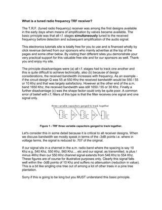
- 1. What is a tuned radio frequency TRF receiver? The T.R.F. (tuned radio frequency) receiver was among the first designs available in the early days when means of amplification by valves became available. The basic principle was that all r.f. stages simultaneously tuned to the received frequency before detection and subsequent amplification of the audio signal. This electronics tutorials site is totally free for you to use and is financed wholly by click revenue derived from our sponsors who mainly advertise at the top of the pages and some other below. By visiting their different sites you demonstrate your very practical support for this valuable free site and for our sponsors as well. Thank you and enjoy my site. The principle disadvantages were (a) all r.f. stages had to track one another and this is quite difficult to achieve technically, also (b) because of design considerations, the received bandwidth increases with frequency. As an example - if the circuit design Q was 55 at 550 Khz the received bandwidth would be 550 / 55 or 10 Khz and that was largely satisfactory. However at the other end of the a.m. band 1650 Khz, the received bandwidth was still 1650 / 55 or 30 Khz. Finally a further disadvantage (c) was the shape factor could only be quite poor. A common error of belief with r.f. filters of this type is that the filter receives one signal and one signal only. Figure 1 - TRF three variable capacitors ganged to track together. Let's consider this in some detail because it is critical to all receiver designs. When we discuss bandwidth we mostly speak in terms of the -3dB points i.e. where in voltage terms, the signal is reduced to .707 of the original. If our signal sits in a channel in the a.m. radio band where the spacing is say 10 Khz e.g. 540 Khz, 550 Khz, 560 Khz.... etc and our signal, as transmitted, is plus / minus 4Khz then our 550 Khz channel signal extends from 546 Khz to 554 Khz. These figures are of course for illustrative purposes only. Clearly this signal falls well within the -3dB points of 10 Khz and suffers no attenuation (reduction in value). This is a bit like singling one tree out of among a lot of other trees in a pine tree plantation. Sorry if this is going to be long but you MUST understand this basic principle.
- 2. Figure 2 - TRF shape factors against ideal In an idealised receiver we would want our signal to have a shape factor of 1:1, i.e. at the adjacent channel spacings we would want an attenuation of say -30 dB where the signal is reduced to .0316 or 3.16% of the original. Consider a long rectangle placed vertically much like a page printed out on your printer. The r.f. filter of 10 Khz occupies the page width at the top of the page and the bottom of the page where the signal is only 3.16% of the original it is still the width of the page. In the real world this never happens. A shape factor of 2:1 would be good for an L.C. filter. This means if the bottom of your page was 20 Khz wide then the middle half of the top of the page would be 10 Khz wide and this would be considered good!. Back to T.R.F. Receivers - their shape factors were nothing like this. Instead of being shaped like a page they tended to look more like a flat sand hill. The reason for this is it is exceedingly difficult or near impossible to build LC Filters with impressive channel spacing and shape factors at frequencies as high as the broadcast band. And this was in the days when the short wave bands (much higher in frequencies) were almost unheard of. Certain embellishments such as the regenerative detector were developed but they were to some extent unsatisfactory. HOME ELECTRONICS COMMUNICATIONS HISTORY TEST EQUIPMENT BUYING GUIDES RESOURCES
- 3. Tuned Radio Frequency Receiver: TRF The TRF, tuned radio frequency radio receiver was widely used in the early days of radio, but is hardly used today The tuned radio frequency receiver is one in which the tuning or selectivity is provided at the radio frequency stages. The tuned radio frequency receiver was used in the early days of wire-less technology but it is rarely used today as other techniques offering much better performance are available. Earliest tuned radio frequency receivers It could be argued that the very earliest tuned radio frequency receivers were crystal sets. These sets used a single tuned network, sometimes consisting of a number of coils. The output from this was fed directly into a crystal or "Cat’s Whisker” " detector and then into headphones.
- 4. Although crystal radios are seldom used these days because their levels of performance can easily be exceeded by other forms of radio, they are ideal for showing some of the basic principles of radio. . . . . . . Read more about the How does a crystal radio work Tuned radio frequency receiver basics The definition of the tuned radio frequency, TRF receiver is a receiver where the tuning, i.e. selectivity is provided by the radio frequency stages. In essence the simplest tuned radio frequency receiver is a simple crystal set. Tuning is provided by a tuned coil / capacitor combination, and then the signal is presented to a simple crystal or diode detector where the amplitude modulated signal, in this case, is recovered. This is then passed straight to the headphones. As vacuum tube / thermionic vale technology developed, these devices were added to provide more gain. Typically a TRF receiver would consist of three main sections: Tuned radio frequency stages: This consisted of one of more amplifying and tuning stages. Early sets often had several stages, each proving some gain and selectivity. Signal detector: The detector enabled the audio from the amplitude modulation signal to be extracted. It used a form of detection called envelope detection and used a diode to rectify the signal. Audio amplifier: Audio stages to provide audio amplification were normally, but not always included. Tuned radio frequency receiver, TRF, block diagram The tuned radio frequency receiver was popular in the 1920s as it provided sufficient gain and selectivity for the receiving the broadcast stations of the day. However tuning took a little while as each stage in the early radios needed to be adjusted separately. Later ganged tuning capacitors were introduced, but by this time the superheterodyne receiver was becoming more widespread. <p<="" p=""> Modern tuned radio frequency receivers The TRF receiver has largely been disregarded in recent years. Other receiver topologies offer far better levels of performance, and with integrated circuit technology, the additional circuitry of other types of receiver is not an issue. There was one attempt at making a sufficiently selective tuned radio frequency receiver integrated circuit.
- 5. The Ferranti ZN414 integrated circuit was introduced in 1972 and was successfully used in a number of designs. Later versions, the ZN415 and ZN416 included audio amplifiers. Performance of the chips was intended to allow operation on the medium wave band, up to frequencies of around 1.6 MHz. Generally the limit of operation of these chips was under 5 MHz. However with the demise of the Ferranti company, the design stopped production. However there have been a few replacement ICs on the market. These include: MK484, YS414, TA7642, UTC7642, LMF501T, LA1050. These can sometimes be purchased on the open market and used in small radios to fit in matchboxes, etc. </p