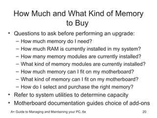
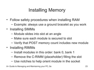
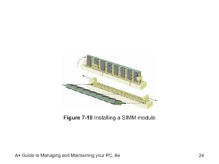
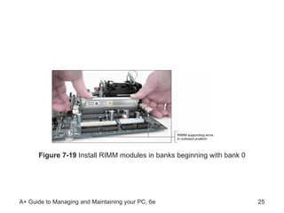
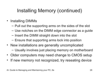
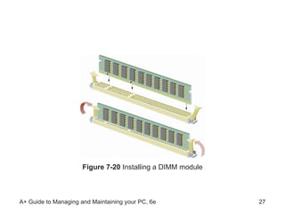
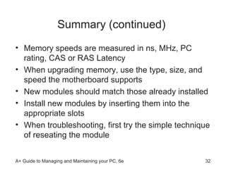
A+ Guide to Managing and Maintaining your PC, 6e Chapter 7 Upgrading Memory
Objectives Learn about the different kinds of physical memory and how they work Learn how to upgrade memory Learn how to troubleshoot problems with memory
Introduction Memory technologies have evolved rapidly  Study development to grasp current technology Memory-related tasks performed by a PC technician  Upgrading memory Adding more memory to a system  Troubleshooting problems with memory
RAM Technologies RAM (random access memory) Holds data and instructions used by CPU  Volatile (data does not persist after PC is turned off)  ROM (read-only memory) In firmware on motherboard; e.g., ROM BIOS  Non-volatile (retains data after PC is turned off) Reviewing other salient features of RAM  RAM is stored in modules: DIMMs, RIMMs, SIMMs Types: static RAM (SRAM) and dynamic RAM (DRAM) Memory cache is made up of SRAM (it is faster)
Figure 7-1  DRAM on most motherboards today is stored on DIMMs
RAM Technologies (continued) Differences among DIMM, RIMM, and SIMM modules Width of the data path each module accommodates The way data moves from system bus to the module  Older DRAM worked asynchronously with system bus Newer DRAM works synchronously with system bus Retrieves data faster as it keeps time with system clock Goal of each new technology Increase overall throughput while retaining accuracy
Figure 7-2  Types of memory modules
SIMM Technologies SIMMS have a 32-bit data path  Speeds (access times): 60, 70, 80 nanoseconds (ns) Smaller number indicates greater speed Components making up the access time Processor requests the data Memory controller locates data on the SIMM Data is placed on the memory bus The processor reads the data off the bus Memory controller refreshes memory chip on SIMM
DIMM Technologies DIMM (dual inline memory module) Has independent pins on opposite sides of module Can have memory chips on one or two sides Has 168, 184, or 240 pins on edge connector Has a 64-bit data path and holds 8 MB - 2 GB RAM Synchronous DRAM (SDRAM) Has two notches, and uses 168 pins DDR (Double Data Rate) and DDR2 DIMM  DDR SDRAM runs 2 x faster than regular SDRAM DDR2 SDRAM is faster than DDR, uses less power
DIMM Technologies (continued) Buffered and registered DIMMs Hold data and amplify a signal before data is written Unbuffered DIMM: no support of buffers or registers SDRAM modules use registers FB-DIMM is fully buffered Notches on module indicate supported technologies Dual channeling  Controller communicates with 2 DIMMs at same time Example: two 64-bit DIMMs form 128-bit data path DIMM pairs must have same size, speed, features
Figure 7-3  The positions of two notches on a SDRAM DIMM identify the type of DIMM and the voltage requirement and also prevent the wrong type from being installed on the motherboard
Figure 7-4  Using dual channels, the memory controller can read from two DIMMs at the same time
RIMM Technologies Direct Rambus DRAM (RDRAM or Direct RDRAM) Uses RIMM memory modules Expensive and slower than current DIMMs C-RIMM (Continuity RIMM): placeholder module Concurrent RDRAM: not as fast as Direct RDRAM Rambus does not actually make RIMMs Licenses technology to memory  manufacturers
Error Checking and Parity Bank: smallest group of working memory chips Example: eight memory chips used in 8-bit data path Parity: error-checking based on an extra (ninth) bit Odd parity: parity bit is set to make odd number of ones  Even parity: parity bit set to make even number of ones Parity error: number of bits conflicts with parity used Example: odd number of bits read in even parity system ECC (error-correcting code) Detects and corrects an error in a single bit  Application: ECC makes 64-bit DIMM a 72-bit module
Figure 7-6  Eight chips and a parity chip hold nine bits that represent the letter A in ASCII with even parity
CAS Latency and RAS Latency Two ways of measuring speed CAS stands for “column access strobe” RAS stands for “row access strobe” Both types measure read/write clock cycles  Two or three clock cycles per column or row of data CAS latency is used more than RAS latency
Tin or Gold Leads Connectors inside memory slots are tin or gold Edge connectors on memory modules follow suit  Tin leads should match tin connectors  Gold leads should match gold connectors  Prevents corrosive chemical reactions between metals
Memory Speeds Measures: ns, MHz, PC rating, CAS or RAS Latency Example: SDRAM, DDR, and RIMM measured in MHz PC rating: total bandwidth between module and CPU  Example: 200 MHz x 8 bytes = 1600 MB/sec = PC1600 Factors to consider when looking at overall speed: How much RAM is installed and the technology used Speed of memory in ns, MHz, or PC rating ECC/parity or non-ECC/nonparity CL or RL rating  Use of dual channeling
How to Upgrade Memory The basic technique: add more RAM modules Problems solved with new memory: Slow performance Applications refusing to load An unstable system Note empty memory slots on most new computers Accommodate new DIMM or RIMM
How Much and What Kind of Memory to Buy  Questions to ask before performing an upgrade: How much memory do I need? How much RAM is currently installed in my system? How many memory modules are currently installed?  What kind of memory modules are currently installed?  How much memory can I fit on my motherboard? What kind of memory can I fit on my motherboard? How do I select and purchase the right memory?  Refer to system utilities to determine capacity  Motherboard documentation guides choice of add-ons
Figure 7-14  How three DIMM slots can use four 64-bit memory banks supported by a motherboard chipset
Figure 7-16  Selecting memory off the Crucial Web site
Installing Memory Follow safety procedures when installing RAM Example: always use a ground bracelet as you work Installing SIMMs Module slides into slot at an angle  Make sure each module is secured to slot Verify that POST memory count includes new module Installing RIMMs Install modules in this order: bank 0, bank 1 Remove the C-RIMM (placeholder) filling the slot Use notches to help orient module in the socket
Figure 7-18  Installing a SIMM module
Figure 7-19  Install RIMM modules in banks beginning with bank 0
Installing Memory (continued) Installing DIMMs Pull out the supporting arms on the sides of the slot  Use notches on the DIMM edge connector as a guide  Insert the DIMM straight down into the slot Ensure that supporting arms lock into position New installations are generally uncomplicated  Usually involves just placing memory on motherboard Older computers may need change to CMOS setup  If new memory not recognized, try reseating device
Figure 7-20  Installing a DIMM module
Troubleshooting Memory Common problems: Boot failure A system that hangs, freezes, or becomes unstable Intermittent application errors General Protection Fault (GPF) errors  Caused by memory errors in Windows
Upgrade Problems Dealing with unrecognized add-on or error message Remove and reinstall the module Check for the suitability of the module for the board Ensure that the module is the correct size Remove the module and check for error message Test the module in another socket Clean the module edge connectors Try flashing BIOS
Recurring Problems Symptoms of an unreliable memory: The system locks up  Error messages about illegal operations often display  General Protection Faults occur during normal operation Some troubleshooting tasks Run updated antivirus software to check for viruses Replace memory modules one at a time Try uninstalling the new hardware Test, reseat, or replace RAM Verify that virtual memory settings are optimized
Summary  RAM categories: static RAM (SRAM), dynamic RAM (dRAM) Modules used to store DRAM: SIMM, DIMM, RIMM Synchronous DRAM (SDRAM): moves to the beat of the system clock Simple parity checks identify one corrupted bit  Error correcting code (ECC) detects and corrects one flipped bit
Summary (continued)  Memory speeds are measured in ns, MHz, PC rating, CAS or RAS Latency When upgrading memory, use the type, size, and speed the motherboard supports  New modules should match those already installed Install new modules by inserting them into the appropriate slots When troubleshooting, first try the simple technique of reseating the module

Chapter 7 Memory

  • 1.
    A+ Guide toManaging and Maintaining your PC, 6e Chapter 7 Upgrading Memory
  • 2.
    Objectives Learn aboutthe different kinds of physical memory and how they work Learn how to upgrade memory Learn how to troubleshoot problems with memory
  • 3.
    Introduction Memory technologieshave evolved rapidly Study development to grasp current technology Memory-related tasks performed by a PC technician Upgrading memory Adding more memory to a system Troubleshooting problems with memory
  • 4.
    RAM Technologies RAM(random access memory) Holds data and instructions used by CPU Volatile (data does not persist after PC is turned off) ROM (read-only memory) In firmware on motherboard; e.g., ROM BIOS Non-volatile (retains data after PC is turned off) Reviewing other salient features of RAM RAM is stored in modules: DIMMs, RIMMs, SIMMs Types: static RAM (SRAM) and dynamic RAM (DRAM) Memory cache is made up of SRAM (it is faster)
  • 5.
    Figure 7-1 DRAM on most motherboards today is stored on DIMMs
  • 6.
    RAM Technologies (continued)Differences among DIMM, RIMM, and SIMM modules Width of the data path each module accommodates The way data moves from system bus to the module Older DRAM worked asynchronously with system bus Newer DRAM works synchronously with system bus Retrieves data faster as it keeps time with system clock Goal of each new technology Increase overall throughput while retaining accuracy
  • 7.
    Figure 7-2 Types of memory modules
  • 8.
    SIMM Technologies SIMMShave a 32-bit data path Speeds (access times): 60, 70, 80 nanoseconds (ns) Smaller number indicates greater speed Components making up the access time Processor requests the data Memory controller locates data on the SIMM Data is placed on the memory bus The processor reads the data off the bus Memory controller refreshes memory chip on SIMM
  • 9.
    DIMM Technologies DIMM(dual inline memory module) Has independent pins on opposite sides of module Can have memory chips on one or two sides Has 168, 184, or 240 pins on edge connector Has a 64-bit data path and holds 8 MB - 2 GB RAM Synchronous DRAM (SDRAM) Has two notches, and uses 168 pins DDR (Double Data Rate) and DDR2 DIMM DDR SDRAM runs 2 x faster than regular SDRAM DDR2 SDRAM is faster than DDR, uses less power
  • 10.
    DIMM Technologies (continued)Buffered and registered DIMMs Hold data and amplify a signal before data is written Unbuffered DIMM: no support of buffers or registers SDRAM modules use registers FB-DIMM is fully buffered Notches on module indicate supported technologies Dual channeling Controller communicates with 2 DIMMs at same time Example: two 64-bit DIMMs form 128-bit data path DIMM pairs must have same size, speed, features
  • 11.
    Figure 7-3 The positions of two notches on a SDRAM DIMM identify the type of DIMM and the voltage requirement and also prevent the wrong type from being installed on the motherboard
  • 12.
    Figure 7-4 Using dual channels, the memory controller can read from two DIMMs at the same time
  • 13.
    RIMM Technologies DirectRambus DRAM (RDRAM or Direct RDRAM) Uses RIMM memory modules Expensive and slower than current DIMMs C-RIMM (Continuity RIMM): placeholder module Concurrent RDRAM: not as fast as Direct RDRAM Rambus does not actually make RIMMs Licenses technology to memory manufacturers
  • 14.
    Error Checking andParity Bank: smallest group of working memory chips Example: eight memory chips used in 8-bit data path Parity: error-checking based on an extra (ninth) bit Odd parity: parity bit is set to make odd number of ones Even parity: parity bit set to make even number of ones Parity error: number of bits conflicts with parity used Example: odd number of bits read in even parity system ECC (error-correcting code) Detects and corrects an error in a single bit Application: ECC makes 64-bit DIMM a 72-bit module
  • 15.
    Figure 7-6 Eight chips and a parity chip hold nine bits that represent the letter A in ASCII with even parity
  • 16.
    CAS Latency andRAS Latency Two ways of measuring speed CAS stands for “column access strobe” RAS stands for “row access strobe” Both types measure read/write clock cycles Two or three clock cycles per column or row of data CAS latency is used more than RAS latency
  • 17.
    Tin or GoldLeads Connectors inside memory slots are tin or gold Edge connectors on memory modules follow suit Tin leads should match tin connectors Gold leads should match gold connectors Prevents corrosive chemical reactions between metals
  • 18.
    Memory Speeds Measures:ns, MHz, PC rating, CAS or RAS Latency Example: SDRAM, DDR, and RIMM measured in MHz PC rating: total bandwidth between module and CPU Example: 200 MHz x 8 bytes = 1600 MB/sec = PC1600 Factors to consider when looking at overall speed: How much RAM is installed and the technology used Speed of memory in ns, MHz, or PC rating ECC/parity or non-ECC/nonparity CL or RL rating Use of dual channeling
  • 19.
    How to UpgradeMemory The basic technique: add more RAM modules Problems solved with new memory: Slow performance Applications refusing to load An unstable system Note empty memory slots on most new computers Accommodate new DIMM or RIMM
  • 20.
    How Much andWhat Kind of Memory to Buy Questions to ask before performing an upgrade: How much memory do I need? How much RAM is currently installed in my system? How many memory modules are currently installed? What kind of memory modules are currently installed? How much memory can I fit on my motherboard? What kind of memory can I fit on my motherboard? How do I select and purchase the right memory? Refer to system utilities to determine capacity Motherboard documentation guides choice of add-ons
  • 21.
    Figure 7-14 How three DIMM slots can use four 64-bit memory banks supported by a motherboard chipset
  • 22.
    Figure 7-16 Selecting memory off the Crucial Web site
  • 23.
    Installing Memory Followsafety procedures when installing RAM Example: always use a ground bracelet as you work Installing SIMMs Module slides into slot at an angle Make sure each module is secured to slot Verify that POST memory count includes new module Installing RIMMs Install modules in this order: bank 0, bank 1 Remove the C-RIMM (placeholder) filling the slot Use notches to help orient module in the socket
  • 24.
    Figure 7-18 Installing a SIMM module
  • 25.
    Figure 7-19 Install RIMM modules in banks beginning with bank 0
  • 26.
    Installing Memory (continued)Installing DIMMs Pull out the supporting arms on the sides of the slot Use notches on the DIMM edge connector as a guide Insert the DIMM straight down into the slot Ensure that supporting arms lock into position New installations are generally uncomplicated Usually involves just placing memory on motherboard Older computers may need change to CMOS setup If new memory not recognized, try reseating device
  • 27.
    Figure 7-20 Installing a DIMM module
  • 28.
    Troubleshooting Memory Commonproblems: Boot failure A system that hangs, freezes, or becomes unstable Intermittent application errors General Protection Fault (GPF) errors Caused by memory errors in Windows
  • 29.
    Upgrade Problems Dealingwith unrecognized add-on or error message Remove and reinstall the module Check for the suitability of the module for the board Ensure that the module is the correct size Remove the module and check for error message Test the module in another socket Clean the module edge connectors Try flashing BIOS
  • 30.
    Recurring Problems Symptomsof an unreliable memory: The system locks up Error messages about illegal operations often display General Protection Faults occur during normal operation Some troubleshooting tasks Run updated antivirus software to check for viruses Replace memory modules one at a time Try uninstalling the new hardware Test, reseat, or replace RAM Verify that virtual memory settings are optimized
  • 31.
    Summary RAMcategories: static RAM (SRAM), dynamic RAM (dRAM) Modules used to store DRAM: SIMM, DIMM, RIMM Synchronous DRAM (SDRAM): moves to the beat of the system clock Simple parity checks identify one corrupted bit Error correcting code (ECC) detects and corrects one flipped bit
  • 32.
    Summary (continued) Memory speeds are measured in ns, MHz, PC rating, CAS or RAS Latency When upgrading memory, use the type, size, and speed the motherboard supports New modules should match those already installed Install new modules by inserting them into the appropriate slots When troubleshooting, first try the simple technique of reseating the module