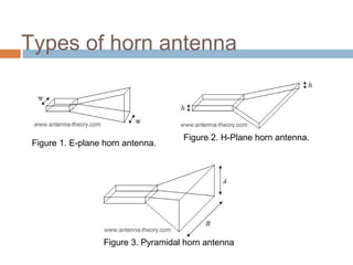
SlideShare a Scribd company logo
CHAPTER 5
MICROWAVE ANTENNAS
5.1.1:
INTRODUCTION OF
MICROWAVE ANTENNA
RADIO W
AVE PROPAGATION
INTRODUCTION

EM waves travel in straight lines, unless acted upon by
some outside force. They travel faster through a vacuum
than through any other medium.
As EM waves spread out from the point of origin, they
decrease in strength in what is described as an inverse
square relationship.
For example: a signal 2 km from its starting point will be
only 1/4 as strong as that 1 km from the source. A signal 3
km from the source will be only 1/9 that at the 1 km point.
RADIO WAVES
x

Electric
Field, E

y
z

Direction of
Propagation

Magnetic
Field, H





Electromagnetic radiation comprises both an Electric and a Magnetic Field.
The two fields are at right-angles to each other and the direction of propagation is at right-angles to both
fields.
The Plane of the Electric Field defines the Polarisation of the wave.
POLARIZATION






The polarization of an antenna is the orientation of
the electric field with respect to the Earth's surface
and is determined by the physical structure of the
antenna and by its orientation.
Radio waves from a vertical antenna will usually
be vertically polarized.
Radio waves from a horizontal antenna are
usually horizontally polarized.
Di
rec
tio
n

of

Pr
op

ag
ati
on

Direction of Propagation
Di
re

cti
o

no

fP
ro
p

ag
a

tio
n

ECM 717 - BY DR MOHD
Direction of Propagation
TARMIZI ALI
Vertically polarized
omnidirectional
dipole antenna

Horizontally polarized directional
yagi antennaDR MOHD
ECM 717 - BY
TARMIZI ALI
W
hat is an ‘antenna’?
 An antenna is a device that is made to efficiently

radiate and receive radiated electromagnetic waves.



An antenna is an electrical conductor or system of
conductors.





Transmission - radiates electromagnetic
energy into space
Reception - collects electromagnetic energy
from space.

In two-way communication, the same antenna can be
used for transmission and reception.
Transmitter

Receiver
5.1.2:
TYPES OF
MICROWAVE ANTENNA
Antenna Types








Horn Antenna
Parabolic Antenna
Slot Antenna
Dipole Antenna
Dielectric Antenna
Printed Antenna
Phase Array Antenna
Horn Antenna






Horn antennas are very popular at UHF (300
MHz-3 GHz) and higher frequencies.
Horn antennas often have a directional radiation
pattern with a high antenna gain, which can range
up to 25 dB in some cases, with 10-20 dB being
typical.
Horn antennas have a wide impedance
bandwidth, implying that the input impedance is
slowly varying over a wide frequency range.
Horn Antenna








The gain of horn antennas often increases as the
frequency of operation is increased.
This is because the size of the horn aperture is always
measured in wavelengths, a higher frequency has a
smaller wavelength.
Since the horn antenna has a fixed physical size, the
aperture is more wavelengths across at higher
frequencies.
Horn antennas have very little loss, so the directivity of
a horn is roughly equal to its gain.
Types of horn antenna

Figure 1. E-plane horn antenna.

Figure 2. H-Plane horn antenna.

Figure 3. Pyramidal horn antenna
Parabolic Antennas
Parabolic Antenna




The most well-known reflector antenna is the parabolic
reflector antenna, commonly known as a satellite dish
antenna.
Examples of this dish antenna are shown in the following
Figures.

Figure 1. The "big dish" antenna of
Stanford University.

Figure 2. A random direcTV dish
antenna on a roof.
Parabolic Antenna








Parabolic reflectors typically have a very high gain (30-40 dB
is common) and low cross polarization.
They also have a reasonable bandwidth, with the fractional
bandwidth being at least 5% on commercially available
models, and can be very wideband in the case of huge dishes.
The smaller dish antennas typically operate somewhere
between 2 and 28 GHz.
The large dishes can operate in the VHF region (30-300 MHz),
but typically need to be extremely large at this operating band.
Slot Antenna








A slot antenna consists of a metal surface, usually
a flat plate, with a hole or slot cut out.
When the plate is driven as an antenna by a
driving frequency, the slot
radiates electromagnetic waves in similar way to
a dipole antenna.
Often the radio waves are provided by
a waveguide, and the antenna consists of slots in
the waveguide.
Slot antennas are used typically at frequencies
Slot Antenna






Slot antennas are often used
at UHF and microwave frequencies instead of line
antennas when greater control of the radiation
pattern is required.
Widely used in radar antennas, for the sector
antennas
used for cell phone base stations.
Often found in standard
desktop microwave sources used for research
purposes.
Slot Antenna
Dipole Antenna










Dipole antenna with a very thin radius is considered.
For very small dipole antennas, the input impedance is
capacitive, which means the impedance is dominated by a
negative reactance value.
As the dipole gets larger, the input resistance increases, along
with the reactance.
At slightly less than 0.5 the antenna has zero imaginary
component to the impedance, and the antenna is said to be
resonant.
If the dipole antenna's length becomes close to one
wavelength, the input impedance becomes infinite.
Dipole antenna basics






Dipole antenna consists of two terminals or "poles" into which
radio frequency current flows.
This current and the associated voltage causes and
electromagnetic or radio signal to be radiated.
Dipole is generally taken to be an antenna that consists of a
resonant length of conductor cut to enable it to be connected
to the feeder.

The basic half wave dipole antenna












The current distribution along a dipole is roughly
sinusoidal.
falls to zero at the end and is at a maximum in the
middle.
voltage is low at the middle and rises to a maximum at
the ends.
It is generally fed at the centre, at the point where the
current is at a maximum and the voltage a minimum.
This provides a low impedance feed point which is
convenient to handle.
High voltage feed points are far less convenient and
more difficult to use.






When multiple half wavelength dipoles are used,
they are similarly normally fed in the centre.
Here again the voltage is at a minimum and the
current at a maximum.
Theoretically any of the current maximum nodes
could be used.
Dipole polar diagram




The polar diagram of a half wave dipole antenna that the
direction of maximum sensitivity or radiation is at right
angles to the axis of the RF antenna.
The radiation falls to zero along the axis of the RF
antenna as might be expected.

Polar diagram of a half wave dipole in free space






If the length of the dipole antenna is changed
then the radiation pattern is altered.
As the length of the antenna is extended it can
be seen that the familiar figure of eight pattern
changes to give main lobes and a few side
lobes.
The main lobes move progressively towards
the axis of the antenna as the length
increases.






The dipole antenna is a particularly important
form of RF antenna which is very widely used
for radio transmitting and receiving
applications.
The dipole is often used on its own as an RF
antenna, but it also forms the essential
element in many other types of RF antenna.
As such it is the possibly the most important
form of RF antenna.
Radiation pattern and gain








Dipoles have a radiation pattern, shaped like a toroid (doughnut)
symmetrical about the axis of the dipole.
The radiation is maximum at right angles to the dipole, dropping off
to zero on the antenna's axis.
The theoretical maximum gain of a Hertzian dipole is 10 log 1.5 or
1.76 dBi.
The maximum theoretical gain of a λ/2-dipole is 10 log 1.64 or 2.15
dBi.
Dipole types





Short dipole
Half-wave dipole
Quarter-wave monopole
Folded dipole
Short dipole






A short dipole is a physically
feasible dipole formed by two
conductors with a total length L
very small compared with the
wavelength λ.
The two conducting wires are fed
at the center of the dipole.
The current is assumed to be
maximal at the center (where the
dipole is fed) and to decrease
linearly to zero at the ends of the
wires.

Half-wave dipole




Typically a dipole antenna is
formed by two quarterwavelength conductors or
elements placed back to back
for a total length of L = λ/2.
The larger the differential
voltage, the greater the current
between the elements.
Quarter-wave monopole




The quarter-wave monopole
antenna is a single-element
antenna fed at one end, that
behaves as a dipole antenna.
The quarter-wave conductor
and its image together form a
half-wave dipole that radiates
only in the upper half of space.

Folded dipole






A folded dipole is a half-wave
dipole with an additional wire
connecting its two ends.
the antenna are folded back until
they almost meet at the feed point,
such that the antenna comprises
one entire wavelength.
This arrangement has a greater
bandwidth than a standard halfwave dipole.
Dielectric Antenna
Dielectric Antenna








An antenna in the form of a section of dielectric rod
excited by a radio wave guide or the post of a coaxial
cable.
A surface wave is generated in the rod of the antenna
and propagates along the axis of the rod.
Dielectric antennas are essentially traveling-wave
antennas, consisting of elementary electric and magnetic
dipoles.
The radiation maximum coincides with the axis of the
rod, as does the maximum of any traveling-wave








The type of radiation of a dielectric antenna depends on the
phase velocity of propagation of the surface wave, which
decreases with an increase in the diameter of the dielectric
rod and in the dielectric constant of its material.
The lower the phase velocity, the greater the length of the rod.
As the phase velocity decreases, or as it approaches the
speed of light in the surrounding medium (air), the dielectric
rod begins to lose its wave-guide properties.
This leads to an abrupt decrease in the field intensity near the
end of the rod, an increase of radiation into the medium
surrounding the antenna (directly from the open end of the
wave guide), and a decrease in the antenna’s efficiency.






The rods of dielectric antennas are made from
dielectric materials with low attenuation of
electromagnetic waves.
Dielectric antennas are used mainly in aircraft
radio equipment, which operates on centimeter
or decimeter wavelengths.
low cost alternative to free space high gain
antenna designs such as Yagi-Uda and horn
antennas, which are often more difficult to
manufacture at these frequencies
Printed Antenna




Printed antenna technology used for wireless
system
Printed antenna application are:
- Arrays for low or medium directivity
- Efficient radiators
- Planar antenna
Printed Antenna


Originated from the use of planar microwave technologies.



The begin antenna printed in the mid 1970.







The layered structure with 2 parallel conductors separated
by a thin dielectric substrate and the lower conductor acting
as a ground plane.
Printed belongs to the class or resonant antennas. Printed
antennas have found use in most classical microwave
applications.
Operates typically from 1- 100 GHz.
Printed Antenna
Phase Array Antenna






A phased array is an array of antennas in which the
relative phases of the respective signals feeding the
antennas are varied in such a way that the effective
radiation pattern of the array is reinforced in a desired
direction and suppressed in undesired directions.
An antenna array is a group of multiple active
antennas coupled to a common source or load to
produce a directive radiation pattern.
Usually, the spatial relationship of the individual
antennas also contributes to the directivity of the
antenna array.
Phase Array Antenna




Use of the term "active antennas" is intended
to describe elements whose energy output is
modified due to the presence of a source of
energy in the element or an element in which
the energy output from a source of energy is
controlled by the signal input.
One common application of this is with a
standard multiband television antenna, which
has multiple elements coupled together.
PAVE PAW Radar Clear AFS
S
Alaska
5.1.3:
TYPES OF FEEDER FOR PARABOLIC
ANTENNA
Feeder Types





Gregorian
Cassegrain
Horn feed
Omnidirectional
Antenna Feed






Antenna feed refers to the components of an antenna which
feed the radio waves to the rest of the antenna structure, or in
receiving antennas collect the incoming radio waves, convert
them to electric currents and transmit them to the receiver.
Antennas typically consist of a feed and additional reflecting or
directive structures whose function is to form the radio waves
from the feed into a beam or other desired radiation pattern.
Feed consists of a dipole driven element, which converts the
radio waves to an electric current, and a coaxial cable or twin
lead transmission line which conducts the received signal from
the antenna into the house to the television receiver.
Gregorian Antenna




It is a type of parabolic antenna used at earth
station
Its design is similar to Cassegrain antenna
(secondary reflector is convex), only
Gregorian antenna’s secondary reflector is
concave
Gregorian antenna




In another word, Gregorian antenna is a
double reflector antenna with the second
reflector located at a distance greater than the
main reflector
In modern world, Gregorian is less compact
than Cassegrain in term of design but with a
smaller second reflector thus the advantages
of beam blocking result in more efficient
antenna
Antenna diagram
Cassegrain Antenna.
Th
i
of s is
ca exa
an sseg mp
ten ra le
na in

Cassegrain antennas are a subcategory of reflector antennas. Reflector
antennas have been used from discovery of electromagnetic wave propagation
Onwards.
Cassegrain antenna consists of two reflectors (primary and secondary) and a
feeder. The main characteristics of Cassegrain antennas is their high
directivity.The bigger diameter of antenna reflector is used, the better
gain is achieved.
Application Cassegrain Antenna.





RADAR.
SPACE COMMUNICATION
RADIO ASTRONOMY
WIRELESS COMMUNICATION.
Operation cassegrain antenna


In telecommunications and radar, a Cassegrain antenna is a parabolic antenna in
which the feed radiator is mounted at or behind the surface of the concave main
parabolic reflector dish and is aimed at a smaller convex secondary reflector
suspended in front of the primary reflector. The beam of radio waves from the
feed illuminates the secondary reflector, which reflects it back to the main
reflector dish, which reflects it forward again to form the desired beam.

n
io
at
er na
op ten
of an
d
te in
ra ra
st eg
Illu ass
c
Cassegrain antenna.
 
Closeup of the convex secondary
reflector in a large satellite
communications antenna in
Pleumeur-Bodou, France

Cassegrain satellite
communication antenna in
Sweden. The convex secondary
reflector can be seen suspended
above the dish, and the feed horn
is visible projecting from the
center of the dish.
RADIATION PATTERN

Another important aspect of the antenna is the front-to-back ratio. It
measures the directivity of the antenna. It is a ratio of energy which
antenna is directing in a particular direction, which depends on its
radiation pattern to the energy which is left behind the antenna or
wasted. The higher the gain of the antenna, the higher the front-toback ratio is. A good antenna front-to-back ratio is normally 20 dB.
Advantage of cassegrain antenna


The feed antennas and associated waveguides and "front end" electronics can be
located on or behind the dish, rather than suspended in front where they block
part of the outgoing beam.



the feed antenna is directed forward, rather than backward toward the dish as in a
front-fed antenna, the spillover side lobes caused by portions of the beam that
miss the secondary reflector are directed upwards toward the sky rather than
downwards towards the warm earth.



Dual reflector shaping: The presence of a second reflector in the signal path allows
additional opportunities for tailoring the radiation pattern for maximum
performance.



increase the focal length of the antenna, to improve the field of view Parabolic
reflectors used in dish antennas have a large curvature and short focal length, to
locate the focal point near the mouth of the dish, to reduce the length of the
supports required to hold the feed structure or secondary reflector.
Disadvantage of cassegrain
antenna


A disadvantage of the Cassegrain is that the feed horn(s) must have a
narrower beamwidth (higher gain) to focus its radiation on the smaller
secondary reflector, instead of the wider primary reflector as in front-fed
dishes. The angular width the secondary reflector subtends at the feed
horn is typically 10° - 15°, as opposed to 120° - 180° the main reflector
subtends in a front-fed dish. Therefore the feed horn must be longer for a
given wavelength.
Horn antenna







Also known as microwave horn, it is an
antenna which is the waveguide is hornshaped
This is to direct radio waves into a beam
Usually used for UHF and microwave
frequency, which is above 300MHz
They used as a feeder (called feed horn) for
larger structure such as parabolic antenna
Feed horn





It is a small horn antenna used to convey radio
waves between transmitter and receiver, and
also the reflector
Generally used in parabolic antenna
Usually used in SHF
Operation


In transmitting antenna, it convert the radio
frequency alternating current from transmitter
to radio waves, which is then feed the radio
waves to the antenna to be focused into beam
Operation


In receiving antenna, the received radio waves
is gathered and focused by the antenna’s
reflector to the feed horn, which is then
converted into radio frequency amplified by
the receiver
Omnidirectional antenna
Th
is
om is e
nid xam
an irec ple
ten tio
o
nn nal f
a.

An omnidirectional antenna is an antenna that has a non-directional pattern (circular pattern) in a given
plane with a directional pattern in any orthogonal plane. Examples of omnidirectional antennas are dipoles
and collinear antennas. In radio communication, an omnidirectional antenna is an antenna which radiates
radio wave power uniformly in all directions in one plane, with the radiated power decreasing with elevation
angle above or below the plane, dropping to zero on the antenna's axis. This radiation pattern is often
described as "doughnut shaped".
Application of omnidirectional
antenna







Cell phones
Fm radio
Walkie talkie
Wireless computer network.
Cordless phone.
Gps
Operation of omnidirectional
antenna.
The omnidirectional antenna radiates or receives equally well in all directions. It is
also called the "non-directional" antenna because it does
not favor any particular direction. The pattern for an omnidirectional antenna, with
the four cardinal signals. This type of pattern is commonly associated with verticals,
ground planes and other antenna types in which the radiator element is vertical with
respect
to the Earth's surface.
Illustrate
block diag
ram
antenna o
mnidirectio
nal
antenna
Radiation pattern omnidirectional antenna

Omnidirectional antennas have a similar radiation pattern. These antennas provide
a 360 degree horizontal radiation pattern. These are used when coverage is
required in all directions (horizontally) from the antenna with varying degrees of
vertical coverage. Polarization is the physical orientation of the element on the
antenna that actually emits the RF energy. An omnidirectional antenna, for
example, is usually a vertical polarized antenna.
Advantage of omnidirectional
antenna
advantage



An omni directional antenne receives or transmits signals from all directions as in
360 degrees.
disadvantage

Signal strength is uniform with omnidirectional antennas.
If you use an omnidirectional antenna all signals are noise sources look into the
same antenna gain. There is neither increase of the desired signal, nor
suppression of undesired signals. On a crowded band, the omnidirectional
antenna confers no SNR
advantage.
5.2:
CHARACTERISTIC OF
HORN & PARABOLIC
ANTENNA
Antenna Radiation Patterns


An antenna radiation pattern or antenna pattern is defined
as a mathematical function or a graphical representation
of the radiation properties of the antenna as a function of
space coordinates.



In most cases, the radiation pattern is determined in the
far field region and is represented as a function of the
directional coordinates.
Types of Radiation Patterns
Idealized
Point Radiator

Isotropic

Vertical Dipole

Omnidirectional

Radar Dish

Directional
Antenna Radiation Pattern
Main beam / side lobe region




The peak of the main beam represents the
highest level of field strength and
approximately 70% of the radiated energy is
enclosed.
The side lobe region represents a potential
source of interference into the communication
link, and for this reason is generally required
to be of low level.
Antenna Side lobes


While most of the power radiated by an antenna
is contained in the ”main lobe", a certain amount
of power can be transmitted, (or received), in offaxis directions.



Side lobes are an intrinsic property of antenna
radiation and cannot be completely eliminated.



However, side lobes are also due to antenna
defects that can be minimized with proper
design.
Horn Antenna Radiation Pattern




This antenna is
simulated using a
commercial solver.
The radiation pattern at
2 GHz is shown in Figure
1.
Figure 1



The gain of the horn is
18.1 dB in the +z-
Parabolic Antenna Radiation
Pattern






This example will be for a parabolic dish reflector with
the diameter of the dish D equal to 11 wavelengths.
A circular horn antenna will be used as the feed.
The maximum gain from the physical aperture is the
actual gain is 29.3 dB = 851, so we can conclude that
the overall efficiency is 77%.
Gain, directivity and efficiency


Gain and directivity are quantities which define
the ability to concentrate energy in a particular
direction and are directly related to the antenna
radiation pattern.



It includes all ohmic and dissipative losses arising
from conductivity of metal and dielectric loss.



Antenna efficiency is a coefficient that accounts
for all the different losses present in an antenna
system.
Antenna Gain
• The fields across the aperture of the parabolic
reflector is responsible for this antenna's
radiation.
• Directivity or gain is the ratio of the power
radiated by an antenna in its direction of
maximum radiation to the power radiated by a
reference antenna in the same direction.
• Is measured in dBi (dB referenced to an
isotropic antenna) or dBd (dB referenced to a
half wavelength dipole).
Antenna Gain


Parabolic Antenna Gain,
G = 6D2/λ2
where D = diameter



Horn Antenna Gain
G = 10A/λ2
A =flange area
Antenna Efficiency
Antenna efficiency is affected by:
1.The sub reflector and supporting structure
blockage.
2.The main reflector rms surface deviation.
3.Illumination efficiency, which accounts for the non
uniformity of the illumination, phase distribution
across the antenna surface, and power radiated in
the side lobes.
4.The power that is radiated in the side lobes.
Radiation Efficiency






The radiation efficiency is the usual efficiency
that deals with ohmic losses.
Horn antennas are often used as feeds, and
these have very little loss.
Parabolic reflector is typically metallic with a
very high conductivity, this efficiency is
typically close to 1 and can be neglected.
The effective antenna aperture is the ratio of the

available power at the terminals of the antenna to
the power flux density of a plane wave incident upon
the antenna, which is polarization matched to the
antenna.

Effective Aperture

If there is no specific direction chosen, the direction

of maximum radiation intensity is implied.
THANK YOU…

More Related Content

What's hot

Horn antenna
Horn antennaHorn antenna
Horn antenna
Alankrit Mishra
 
Multiple access techniques
Multiple access techniquesMultiple access techniques
Multiple access techniques
RCC Institute of Information Technology
 
microwave-tubes
 microwave-tubes microwave-tubes
microwave-tubes
ATTO RATHORE
 
Antenna Basics
Antenna BasicsAntenna Basics
Antenna Basics
Md Mustafizur Rahman
 
Antennas and Wave Propagation
Antennas and Wave Propagation Antennas and Wave Propagation
Antennas and Wave Propagation
VenkataRatnam14
 
Microwave link budget
Microwave link budgetMicrowave link budget
Microwave link budget
Akram AL-khazaliy
 
optical transmitter
optical transmitteroptical transmitter
optical transmitter
@zenafaris91
 
Microwave basics
Microwave basicsMicrowave basics
Microwave basics
Islam Saleh
 
Antenna PARAMETERS
Antenna PARAMETERSAntenna PARAMETERS
Antenna PARAMETERS
AJAL A J
 
Antenna
AntennaAntenna
Cw and fm cw radar
Cw and fm cw radarCw and fm cw radar
Cw and fm cw radar
Vijendrasingh Rathor
 
Microstripline
MicrostriplineMicrostripline
Microstripline
Aysu COSKUN
 
OPTICAL COMMUNICATION Unit 2
OPTICAL COMMUNICATION Unit 2OPTICAL COMMUNICATION Unit 2
OPTICAL COMMUNICATION Unit 2
Asif Iqbal
 
Microstrip patch antenna with DGS
Microstrip patch antenna with DGSMicrostrip patch antenna with DGS
Microstrip patch antenna with DGS
Ankit Pandey
 
Ultra wideband technology (UWB)
Ultra wideband technology (UWB)Ultra wideband technology (UWB)
Ultra wideband technology (UWB)
Mustafa Khaleel
 
EC6602-Antenna fundamentals new
EC6602-Antenna fundamentals new EC6602-Antenna fundamentals new
EC6602-Antenna fundamentals new
krishnamrm
 
smart antennas ppt
smart antennas pptsmart antennas ppt
smart antennas ppt
santhu652
 
Radio Wave propagation
Radio Wave propagationRadio Wave propagation
Radio Wave propagation
Ritika De
 

What's hot (20)

Horn antenna
Horn antennaHorn antenna
Horn antenna
 
Multiple access techniques
Multiple access techniquesMultiple access techniques
Multiple access techniques
 
microwave-tubes
 microwave-tubes microwave-tubes
microwave-tubes
 
Antenna Basics
Antenna BasicsAntenna Basics
Antenna Basics
 
Antennas and Wave Propagation
Antennas and Wave Propagation Antennas and Wave Propagation
Antennas and Wave Propagation
 
Microwave link budget
Microwave link budgetMicrowave link budget
Microwave link budget
 
Antenna (2)
Antenna (2)Antenna (2)
Antenna (2)
 
optical transmitter
optical transmitteroptical transmitter
optical transmitter
 
Microwave basics
Microwave basicsMicrowave basics
Microwave basics
 
Antenna PARAMETERS
Antenna PARAMETERSAntenna PARAMETERS
Antenna PARAMETERS
 
Antenna
AntennaAntenna
Antenna
 
Cw and fm cw radar
Cw and fm cw radarCw and fm cw radar
Cw and fm cw radar
 
Microstripline
MicrostriplineMicrostripline
Microstripline
 
OPTICAL COMMUNICATION Unit 2
OPTICAL COMMUNICATION Unit 2OPTICAL COMMUNICATION Unit 2
OPTICAL COMMUNICATION Unit 2
 
Microstrip patch antenna with DGS
Microstrip patch antenna with DGSMicrostrip patch antenna with DGS
Microstrip patch antenna with DGS
 
Ultra wideband technology (UWB)
Ultra wideband technology (UWB)Ultra wideband technology (UWB)
Ultra wideband technology (UWB)
 
EC6602-Antenna fundamentals new
EC6602-Antenna fundamentals new EC6602-Antenna fundamentals new
EC6602-Antenna fundamentals new
 
Spiral Antenna
Spiral Antenna  Spiral Antenna
Spiral Antenna
 
smart antennas ppt
smart antennas pptsmart antennas ppt
smart antennas ppt
 
Radio Wave propagation
Radio Wave propagationRadio Wave propagation
Radio Wave propagation
 

Viewers also liked

Point to point microwave
Point to point microwavePoint to point microwave
Point to point microwave
nandkishorsuman
 
Modulation by sanjay
Modulation by sanjay Modulation by sanjay
Modulation by sanjay Sanjay Songra
 
Frequency modulation
Frequency modulationFrequency modulation
Frequency modulation
Akanksha_Seth
 
Fm
FmFm
Amplitude Modulation ppt
Amplitude Modulation pptAmplitude Modulation ppt
Amplitude Modulation ppt
Priyanka Mathur
 
Antenna types
Antenna typesAntenna types
Antenna types
youssef ramzy
 
Antenna basics
Antenna basicsAntenna basics
Antenna basicsjpratt59
 
Cdma presentation final
Cdma presentation finalCdma presentation final
Cdma presentation finalAmit Gaikwad
 
Routing over ericsson mini link
Routing over ericsson mini linkRouting over ericsson mini link
Routing over ericsson mini link
Ahmed Nabeeh
 
Chap06 Telecommunications and Networks
Chap06 Telecommunications and NetworksChap06 Telecommunications and Networks
Chap06 Telecommunications and Networks
Turu Turuu
 
Training on microwave communication
Training on microwave communicationTraining on microwave communication
Training on microwave communication
Tempus Telcosys
 
Microwave_Transmission_Associate Certification
Microwave_Transmission_Associate CertificationMicrowave_Transmission_Associate Certification
Microwave_Transmission_Associate Certificationahmed kamal
 
Microwave_Transmission_Professional_Certification
Microwave_Transmission_Professional_CertificationMicrowave_Transmission_Professional_Certification
Microwave_Transmission_Professional_Certificationahmed kamal
 
Microwave Transmission
Microwave TransmissionMicrowave Transmission
Microwave TransmissionDevang Bhatti
 
Gsm
GsmGsm
Digital microwave communication principles
Digital microwave communication principles Digital microwave communication principles
Digital microwave communication principles Mohamed Sewailam
 
Microwave link communication system
Microwave link communication systemMicrowave link communication system
Microwave link communication systembillyjoe585
 
CDMA
CDMACDMA
Mw training slide
Mw training slideMw training slide
Mw training slidededoyin
 

Viewers also liked (20)

Point to point microwave
Point to point microwavePoint to point microwave
Point to point microwave
 
Modulation by sanjay
Modulation by sanjay Modulation by sanjay
Modulation by sanjay
 
Frequency modulation
Frequency modulationFrequency modulation
Frequency modulation
 
Fm
FmFm
Fm
 
Amplitude Modulation ppt
Amplitude Modulation pptAmplitude Modulation ppt
Amplitude Modulation ppt
 
Introduction to mapinfo
Introduction to mapinfoIntroduction to mapinfo
Introduction to mapinfo
 
Antenna types
Antenna typesAntenna types
Antenna types
 
Antenna basics
Antenna basicsAntenna basics
Antenna basics
 
Cdma presentation final
Cdma presentation finalCdma presentation final
Cdma presentation final
 
Routing over ericsson mini link
Routing over ericsson mini linkRouting over ericsson mini link
Routing over ericsson mini link
 
Chap06 Telecommunications and Networks
Chap06 Telecommunications and NetworksChap06 Telecommunications and Networks
Chap06 Telecommunications and Networks
 
Training on microwave communication
Training on microwave communicationTraining on microwave communication
Training on microwave communication
 
Microwave_Transmission_Associate Certification
Microwave_Transmission_Associate CertificationMicrowave_Transmission_Associate Certification
Microwave_Transmission_Associate Certification
 
Microwave_Transmission_Professional_Certification
Microwave_Transmission_Professional_CertificationMicrowave_Transmission_Professional_Certification
Microwave_Transmission_Professional_Certification
 
Microwave Transmission
Microwave TransmissionMicrowave Transmission
Microwave Transmission
 
Gsm
GsmGsm
Gsm
 
Digital microwave communication principles
Digital microwave communication principles Digital microwave communication principles
Digital microwave communication principles
 
Microwave link communication system
Microwave link communication systemMicrowave link communication system
Microwave link communication system
 
CDMA
CDMACDMA
CDMA
 
Mw training slide
Mw training slideMw training slide
Mw training slide
 

Similar to Microwave Antenna

Microwave Antenna -- MW Transmission
Microwave Antenna -- MW TransmissionMicrowave Antenna -- MW Transmission
Microwave Antenna -- MW Transmission
Mohamed Sewailam
 
Antennas Part I slides.pdf
Antennas Part I slides.pdfAntennas Part I slides.pdf
Antennas Part I slides.pdf
PhumzileMalindi
 
N 6-ee302-lesson-13-antenna-fundamentals
N 6-ee302-lesson-13-antenna-fundamentalsN 6-ee302-lesson-13-antenna-fundamentals
N 6-ee302-lesson-13-antenna-fundamentals
15010192
 
Antenna
AntennaAntenna
Dipole antenna aerial tutorial
Dipole antenna  aerial tutorialDipole antenna  aerial tutorial
Dipole antenna aerial tutorial
Manoj Kumar Rai
 
Fundamentals of cellular antenna creating magic in the air
Fundamentals of cellular antenna creating magic in the airFundamentals of cellular antenna creating magic in the air
Fundamentals of cellular antenna creating magic in the air
Sukhvinder Singh Malik
 
Antennas
AntennasAntennas
Antennas
irfan sultan
 
ppt of BE
ppt of BEppt of BE
ppt of BE
Nirali Akabari
 
RADIO ENGINEERING Week 9 Lecture 9 various types of antenna
RADIO ENGINEERINGWeek 9 Lecture 9various types of antennaRADIO ENGINEERINGWeek 9 Lecture 9various types of antenna
RADIO ENGINEERING Week 9 Lecture 9 various types of antenna
MdSharifUddinShajib
 
DESIGN AND ANALYSIS OF DISCONE ANTENNA
DESIGN AND ANALYSIS OF DISCONE ANTENNADESIGN AND ANALYSIS OF DISCONE ANTENNA
Antenna and It's Parameters by YEASIN NEWAJ
Antenna and It's Parameters by YEASIN NEWAJ Antenna and It's Parameters by YEASIN NEWAJ
Antenna and It's Parameters by YEASIN NEWAJ
YeasinNewaj
 
Dipole Antenna Design, Working, and Types.pdf
Dipole Antenna Design, Working, and Types.pdfDipole Antenna Design, Working, and Types.pdf
Dipole Antenna Design, Working, and Types.pdf
Gurleen Nayar
 
Design of a 600 mhz ddipole antenna
Design of a 600 mhz ddipole antennaDesign of a 600 mhz ddipole antenna
Design of a 600 mhz ddipole antenna
Sabrina Chowdhury
 
lec-antennas.ppt
lec-antennas.pptlec-antennas.ppt
lec-antennas.ppt
ADITYABHARDWAJ165456
 
lec-antennas.ppt
lec-antennas.pptlec-antennas.ppt
lec-antennas.ppt
FirstknightPhyo
 
Half wave dipole antenna
Half wave dipole antennaHalf wave dipole antenna
Half wave dipole antenna
Roshan Kattel
 
Fianl Year Project Report
Fianl Year Project ReportFianl Year Project Report
Fianl Year Project ReportShruti Nadkarni
 
Dipole Antenna Design, Working, Application, and Types (1).pdf
Dipole Antenna Design, Working, Application, and Types (1).pdfDipole Antenna Design, Working, Application, and Types (1).pdf
Dipole Antenna Design, Working, Application, and Types (1).pdf
Gurleen Nayar
 
Antenna
AntennaAntenna
Antenna
Izah Asmadi
 

Similar to Microwave Antenna (20)

Microwave Antenna -- MW Transmission
Microwave Antenna -- MW TransmissionMicrowave Antenna -- MW Transmission
Microwave Antenna -- MW Transmission
 
antennas
antennasantennas
antennas
 
Antennas Part I slides.pdf
Antennas Part I slides.pdfAntennas Part I slides.pdf
Antennas Part I slides.pdf
 
N 6-ee302-lesson-13-antenna-fundamentals
N 6-ee302-lesson-13-antenna-fundamentalsN 6-ee302-lesson-13-antenna-fundamentals
N 6-ee302-lesson-13-antenna-fundamentals
 
Antenna
AntennaAntenna
Antenna
 
Dipole antenna aerial tutorial
Dipole antenna  aerial tutorialDipole antenna  aerial tutorial
Dipole antenna aerial tutorial
 
Fundamentals of cellular antenna creating magic in the air
Fundamentals of cellular antenna creating magic in the airFundamentals of cellular antenna creating magic in the air
Fundamentals of cellular antenna creating magic in the air
 
Antennas
AntennasAntennas
Antennas
 
ppt of BE
ppt of BEppt of BE
ppt of BE
 
RADIO ENGINEERING Week 9 Lecture 9 various types of antenna
RADIO ENGINEERINGWeek 9 Lecture 9various types of antennaRADIO ENGINEERINGWeek 9 Lecture 9various types of antenna
RADIO ENGINEERING Week 9 Lecture 9 various types of antenna
 
DESIGN AND ANALYSIS OF DISCONE ANTENNA
DESIGN AND ANALYSIS OF DISCONE ANTENNADESIGN AND ANALYSIS OF DISCONE ANTENNA
DESIGN AND ANALYSIS OF DISCONE ANTENNA
 
Antenna and It's Parameters by YEASIN NEWAJ
Antenna and It's Parameters by YEASIN NEWAJ Antenna and It's Parameters by YEASIN NEWAJ
Antenna and It's Parameters by YEASIN NEWAJ
 
Dipole Antenna Design, Working, and Types.pdf
Dipole Antenna Design, Working, and Types.pdfDipole Antenna Design, Working, and Types.pdf
Dipole Antenna Design, Working, and Types.pdf
 
Design of a 600 mhz ddipole antenna
Design of a 600 mhz ddipole antennaDesign of a 600 mhz ddipole antenna
Design of a 600 mhz ddipole antenna
 
lec-antennas.ppt
lec-antennas.pptlec-antennas.ppt
lec-antennas.ppt
 
lec-antennas.ppt
lec-antennas.pptlec-antennas.ppt
lec-antennas.ppt
 
Half wave dipole antenna
Half wave dipole antennaHalf wave dipole antenna
Half wave dipole antenna
 
Fianl Year Project Report
Fianl Year Project ReportFianl Year Project Report
Fianl Year Project Report
 
Dipole Antenna Design, Working, Application, and Types (1).pdf
Dipole Antenna Design, Working, Application, and Types (1).pdfDipole Antenna Design, Working, Application, and Types (1).pdf
Dipole Antenna Design, Working, Application, and Types (1).pdf
 
Antenna
AntennaAntenna
Antenna
 

Recently uploaded

special B.ed 2nd year old paper_20240531.pdf
special B.ed 2nd year old paper_20240531.pdfspecial B.ed 2nd year old paper_20240531.pdf
special B.ed 2nd year old paper_20240531.pdf
Special education needs
 
PART A. Introduction to Costumer Service
PART A. Introduction to Costumer ServicePART A. Introduction to Costumer Service
PART A. Introduction to Costumer Service
PedroFerreira53928
 
aaaaaaaaaaaaaaaaaaaaaaaaaaaaaaaaaaaaaaaaa
aaaaaaaaaaaaaaaaaaaaaaaaaaaaaaaaaaaaaaaaaaaaaaaaaaaaaaaaaaaaaaaaaaaaaaaaaaaaaaaaaa
aaaaaaaaaaaaaaaaaaaaaaaaaaaaaaaaaaaaaaaaa
siemaillard
 
ESC Beyond Borders _From EU to You_ InfoPack general.pdf
ESC Beyond Borders _From EU to You_ InfoPack general.pdfESC Beyond Borders _From EU to You_ InfoPack general.pdf
ESC Beyond Borders _From EU to You_ InfoPack general.pdf
Fundacja Rozwoju Społeczeństwa Przedsiębiorczego
 
GIÁO ÁN DẠY THÊM (KẾ HOẠCH BÀI BUỔI 2) - TIẾNG ANH 8 GLOBAL SUCCESS (2 CỘT) N...
GIÁO ÁN DẠY THÊM (KẾ HOẠCH BÀI BUỔI 2) - TIẾNG ANH 8 GLOBAL SUCCESS (2 CỘT) N...GIÁO ÁN DẠY THÊM (KẾ HOẠCH BÀI BUỔI 2) - TIẾNG ANH 8 GLOBAL SUCCESS (2 CỘT) N...
GIÁO ÁN DẠY THÊM (KẾ HOẠCH BÀI BUỔI 2) - TIẾNG ANH 8 GLOBAL SUCCESS (2 CỘT) N...
Nguyen Thanh Tu Collection
 
Thesis Statement for students diagnonsed withADHD.ppt
Thesis Statement for students diagnonsed withADHD.pptThesis Statement for students diagnonsed withADHD.ppt
Thesis Statement for students diagnonsed withADHD.ppt
EverAndrsGuerraGuerr
 
Polish students' mobility in the Czech Republic
Polish students' mobility in the Czech RepublicPolish students' mobility in the Czech Republic
Polish students' mobility in the Czech Republic
Anna Sz.
 
Chapter 3 - Islamic Banking Products and Services.pptx
Chapter 3 - Islamic Banking Products and Services.pptxChapter 3 - Islamic Banking Products and Services.pptx
Chapter 3 - Islamic Banking Products and Services.pptx
Mohd Adib Abd Muin, Senior Lecturer at Universiti Utara Malaysia
 
Sha'Carri Richardson Presentation 202345
Sha'Carri Richardson Presentation 202345Sha'Carri Richardson Presentation 202345
Sha'Carri Richardson Presentation 202345
beazzy04
 
The Roman Empire A Historical Colossus.pdf
The Roman Empire A Historical Colossus.pdfThe Roman Empire A Historical Colossus.pdf
The Roman Empire A Historical Colossus.pdf
kaushalkr1407
 
Sectors of the Indian Economy - Class 10 Study Notes pdf
Sectors of the Indian Economy - Class 10 Study Notes pdfSectors of the Indian Economy - Class 10 Study Notes pdf
Sectors of the Indian Economy - Class 10 Study Notes pdf
Vivekanand Anglo Vedic Academy
 
TESDA TM1 REVIEWER FOR NATIONAL ASSESSMENT WRITTEN AND ORAL QUESTIONS WITH A...
TESDA TM1 REVIEWER  FOR NATIONAL ASSESSMENT WRITTEN AND ORAL QUESTIONS WITH A...TESDA TM1 REVIEWER  FOR NATIONAL ASSESSMENT WRITTEN AND ORAL QUESTIONS WITH A...
TESDA TM1 REVIEWER FOR NATIONAL ASSESSMENT WRITTEN AND ORAL QUESTIONS WITH A...
EugeneSaldivar
 
2024.06.01 Introducing a competency framework for languag learning materials ...
2024.06.01 Introducing a competency framework for languag learning materials ...2024.06.01 Introducing a competency framework for languag learning materials ...
2024.06.01 Introducing a competency framework for languag learning materials ...
Sandy Millin
 
Home assignment II on Spectroscopy 2024 Answers.pdf
Home assignment II on Spectroscopy 2024 Answers.pdfHome assignment II on Spectroscopy 2024 Answers.pdf
Home assignment II on Spectroscopy 2024 Answers.pdf
Tamralipta Mahavidyalaya
 
How libraries can support authors with open access requirements for UKRI fund...
How libraries can support authors with open access requirements for UKRI fund...How libraries can support authors with open access requirements for UKRI fund...
How libraries can support authors with open access requirements for UKRI fund...
Jisc
 
Operation Blue Star - Saka Neela Tara
Operation Blue Star   -  Saka Neela TaraOperation Blue Star   -  Saka Neela Tara
Operation Blue Star - Saka Neela Tara
Balvir Singh
 
Cambridge International AS A Level Biology Coursebook - EBook (MaryFosbery J...
Cambridge International AS  A Level Biology Coursebook - EBook (MaryFosbery J...Cambridge International AS  A Level Biology Coursebook - EBook (MaryFosbery J...
Cambridge International AS A Level Biology Coursebook - EBook (MaryFosbery J...
AzmatAli747758
 
Language Across the Curriculm LAC B.Ed.
Language Across the  Curriculm LAC B.Ed.Language Across the  Curriculm LAC B.Ed.
Language Across the Curriculm LAC B.Ed.
Atul Kumar Singh
 
Phrasal Verbs.XXXXXXXXXXXXXXXXXXXXXXXXXX
Phrasal Verbs.XXXXXXXXXXXXXXXXXXXXXXXXXXPhrasal Verbs.XXXXXXXXXXXXXXXXXXXXXXXXXX
Phrasal Verbs.XXXXXXXXXXXXXXXXXXXXXXXXXX
MIRIAMSALINAS13
 
Mule 4.6 & Java 17 Upgrade | MuleSoft Mysore Meetup #46
Mule 4.6 & Java 17 Upgrade | MuleSoft Mysore Meetup #46Mule 4.6 & Java 17 Upgrade | MuleSoft Mysore Meetup #46
Mule 4.6 & Java 17 Upgrade | MuleSoft Mysore Meetup #46
MysoreMuleSoftMeetup
 

Recently uploaded (20)

special B.ed 2nd year old paper_20240531.pdf
special B.ed 2nd year old paper_20240531.pdfspecial B.ed 2nd year old paper_20240531.pdf
special B.ed 2nd year old paper_20240531.pdf
 
PART A. Introduction to Costumer Service
PART A. Introduction to Costumer ServicePART A. Introduction to Costumer Service
PART A. Introduction to Costumer Service
 
aaaaaaaaaaaaaaaaaaaaaaaaaaaaaaaaaaaaaaaaa
aaaaaaaaaaaaaaaaaaaaaaaaaaaaaaaaaaaaaaaaaaaaaaaaaaaaaaaaaaaaaaaaaaaaaaaaaaaaaaaaaa
aaaaaaaaaaaaaaaaaaaaaaaaaaaaaaaaaaaaaaaaa
 
ESC Beyond Borders _From EU to You_ InfoPack general.pdf
ESC Beyond Borders _From EU to You_ InfoPack general.pdfESC Beyond Borders _From EU to You_ InfoPack general.pdf
ESC Beyond Borders _From EU to You_ InfoPack general.pdf
 
GIÁO ÁN DẠY THÊM (KẾ HOẠCH BÀI BUỔI 2) - TIẾNG ANH 8 GLOBAL SUCCESS (2 CỘT) N...
GIÁO ÁN DẠY THÊM (KẾ HOẠCH BÀI BUỔI 2) - TIẾNG ANH 8 GLOBAL SUCCESS (2 CỘT) N...GIÁO ÁN DẠY THÊM (KẾ HOẠCH BÀI BUỔI 2) - TIẾNG ANH 8 GLOBAL SUCCESS (2 CỘT) N...
GIÁO ÁN DẠY THÊM (KẾ HOẠCH BÀI BUỔI 2) - TIẾNG ANH 8 GLOBAL SUCCESS (2 CỘT) N...
 
Thesis Statement for students diagnonsed withADHD.ppt
Thesis Statement for students diagnonsed withADHD.pptThesis Statement for students diagnonsed withADHD.ppt
Thesis Statement for students diagnonsed withADHD.ppt
 
Polish students' mobility in the Czech Republic
Polish students' mobility in the Czech RepublicPolish students' mobility in the Czech Republic
Polish students' mobility in the Czech Republic
 
Chapter 3 - Islamic Banking Products and Services.pptx
Chapter 3 - Islamic Banking Products and Services.pptxChapter 3 - Islamic Banking Products and Services.pptx
Chapter 3 - Islamic Banking Products and Services.pptx
 
Sha'Carri Richardson Presentation 202345
Sha'Carri Richardson Presentation 202345Sha'Carri Richardson Presentation 202345
Sha'Carri Richardson Presentation 202345
 
The Roman Empire A Historical Colossus.pdf
The Roman Empire A Historical Colossus.pdfThe Roman Empire A Historical Colossus.pdf
The Roman Empire A Historical Colossus.pdf
 
Sectors of the Indian Economy - Class 10 Study Notes pdf
Sectors of the Indian Economy - Class 10 Study Notes pdfSectors of the Indian Economy - Class 10 Study Notes pdf
Sectors of the Indian Economy - Class 10 Study Notes pdf
 
TESDA TM1 REVIEWER FOR NATIONAL ASSESSMENT WRITTEN AND ORAL QUESTIONS WITH A...
TESDA TM1 REVIEWER  FOR NATIONAL ASSESSMENT WRITTEN AND ORAL QUESTIONS WITH A...TESDA TM1 REVIEWER  FOR NATIONAL ASSESSMENT WRITTEN AND ORAL QUESTIONS WITH A...
TESDA TM1 REVIEWER FOR NATIONAL ASSESSMENT WRITTEN AND ORAL QUESTIONS WITH A...
 
2024.06.01 Introducing a competency framework for languag learning materials ...
2024.06.01 Introducing a competency framework for languag learning materials ...2024.06.01 Introducing a competency framework for languag learning materials ...
2024.06.01 Introducing a competency framework for languag learning materials ...
 
Home assignment II on Spectroscopy 2024 Answers.pdf
Home assignment II on Spectroscopy 2024 Answers.pdfHome assignment II on Spectroscopy 2024 Answers.pdf
Home assignment II on Spectroscopy 2024 Answers.pdf
 
How libraries can support authors with open access requirements for UKRI fund...
How libraries can support authors with open access requirements for UKRI fund...How libraries can support authors with open access requirements for UKRI fund...
How libraries can support authors with open access requirements for UKRI fund...
 
Operation Blue Star - Saka Neela Tara
Operation Blue Star   -  Saka Neela TaraOperation Blue Star   -  Saka Neela Tara
Operation Blue Star - Saka Neela Tara
 
Cambridge International AS A Level Biology Coursebook - EBook (MaryFosbery J...
Cambridge International AS  A Level Biology Coursebook - EBook (MaryFosbery J...Cambridge International AS  A Level Biology Coursebook - EBook (MaryFosbery J...
Cambridge International AS A Level Biology Coursebook - EBook (MaryFosbery J...
 
Language Across the Curriculm LAC B.Ed.
Language Across the  Curriculm LAC B.Ed.Language Across the  Curriculm LAC B.Ed.
Language Across the Curriculm LAC B.Ed.
 
Phrasal Verbs.XXXXXXXXXXXXXXXXXXXXXXXXXX
Phrasal Verbs.XXXXXXXXXXXXXXXXXXXXXXXXXXPhrasal Verbs.XXXXXXXXXXXXXXXXXXXXXXXXXX
Phrasal Verbs.XXXXXXXXXXXXXXXXXXXXXXXXXX
 
Mule 4.6 & Java 17 Upgrade | MuleSoft Mysore Meetup #46
Mule 4.6 & Java 17 Upgrade | MuleSoft Mysore Meetup #46Mule 4.6 & Java 17 Upgrade | MuleSoft Mysore Meetup #46
Mule 4.6 & Java 17 Upgrade | MuleSoft Mysore Meetup #46
 

Microwave Antenna

  • 3. RADIO W AVE PROPAGATION INTRODUCTION EM waves travel in straight lines, unless acted upon by some outside force. They travel faster through a vacuum than through any other medium. As EM waves spread out from the point of origin, they decrease in strength in what is described as an inverse square relationship. For example: a signal 2 km from its starting point will be only 1/4 as strong as that 1 km from the source. A signal 3 km from the source will be only 1/9 that at the 1 km point.
  • 4. RADIO WAVES x Electric Field, E y z Direction of Propagation Magnetic Field, H    Electromagnetic radiation comprises both an Electric and a Magnetic Field. The two fields are at right-angles to each other and the direction of propagation is at right-angles to both fields. The Plane of the Electric Field defines the Polarisation of the wave.
  • 5. POLARIZATION    The polarization of an antenna is the orientation of the electric field with respect to the Earth's surface and is determined by the physical structure of the antenna and by its orientation. Radio waves from a vertical antenna will usually be vertically polarized. Radio waves from a horizontal antenna are usually horizontally polarized.
  • 7. Vertically polarized omnidirectional dipole antenna Horizontally polarized directional yagi antennaDR MOHD ECM 717 - BY TARMIZI ALI
  • 8. W hat is an ‘antenna’?  An antenna is a device that is made to efficiently radiate and receive radiated electromagnetic waves.  An antenna is an electrical conductor or system of conductors.    Transmission - radiates electromagnetic energy into space Reception - collects electromagnetic energy from space. In two-way communication, the same antenna can be used for transmission and reception.
  • 11. Antenna Types        Horn Antenna Parabolic Antenna Slot Antenna Dipole Antenna Dielectric Antenna Printed Antenna Phase Array Antenna
  • 12. Horn Antenna    Horn antennas are very popular at UHF (300 MHz-3 GHz) and higher frequencies. Horn antennas often have a directional radiation pattern with a high antenna gain, which can range up to 25 dB in some cases, with 10-20 dB being typical. Horn antennas have a wide impedance bandwidth, implying that the input impedance is slowly varying over a wide frequency range.
  • 13. Horn Antenna     The gain of horn antennas often increases as the frequency of operation is increased. This is because the size of the horn aperture is always measured in wavelengths, a higher frequency has a smaller wavelength. Since the horn antenna has a fixed physical size, the aperture is more wavelengths across at higher frequencies. Horn antennas have very little loss, so the directivity of a horn is roughly equal to its gain.
  • 14. Types of horn antenna Figure 1. E-plane horn antenna. Figure 2. H-Plane horn antenna. Figure 3. Pyramidal horn antenna
  • 16. Parabolic Antenna   The most well-known reflector antenna is the parabolic reflector antenna, commonly known as a satellite dish antenna. Examples of this dish antenna are shown in the following Figures. Figure 1. The "big dish" antenna of Stanford University. Figure 2. A random direcTV dish antenna on a roof.
  • 17. Parabolic Antenna     Parabolic reflectors typically have a very high gain (30-40 dB is common) and low cross polarization. They also have a reasonable bandwidth, with the fractional bandwidth being at least 5% on commercially available models, and can be very wideband in the case of huge dishes. The smaller dish antennas typically operate somewhere between 2 and 28 GHz. The large dishes can operate in the VHF region (30-300 MHz), but typically need to be extremely large at this operating band.
  • 18. Slot Antenna     A slot antenna consists of a metal surface, usually a flat plate, with a hole or slot cut out. When the plate is driven as an antenna by a driving frequency, the slot radiates electromagnetic waves in similar way to a dipole antenna. Often the radio waves are provided by a waveguide, and the antenna consists of slots in the waveguide. Slot antennas are used typically at frequencies
  • 19. Slot Antenna    Slot antennas are often used at UHF and microwave frequencies instead of line antennas when greater control of the radiation pattern is required. Widely used in radar antennas, for the sector antennas used for cell phone base stations. Often found in standard desktop microwave sources used for research purposes.
  • 21. Dipole Antenna      Dipole antenna with a very thin radius is considered. For very small dipole antennas, the input impedance is capacitive, which means the impedance is dominated by a negative reactance value. As the dipole gets larger, the input resistance increases, along with the reactance. At slightly less than 0.5 the antenna has zero imaginary component to the impedance, and the antenna is said to be resonant. If the dipole antenna's length becomes close to one wavelength, the input impedance becomes infinite.
  • 22. Dipole antenna basics    Dipole antenna consists of two terminals or "poles" into which radio frequency current flows. This current and the associated voltage causes and electromagnetic or radio signal to be radiated. Dipole is generally taken to be an antenna that consists of a resonant length of conductor cut to enable it to be connected to the feeder. The basic half wave dipole antenna
  • 23.       The current distribution along a dipole is roughly sinusoidal. falls to zero at the end and is at a maximum in the middle. voltage is low at the middle and rises to a maximum at the ends. It is generally fed at the centre, at the point where the current is at a maximum and the voltage a minimum. This provides a low impedance feed point which is convenient to handle. High voltage feed points are far less convenient and more difficult to use.
  • 24.    When multiple half wavelength dipoles are used, they are similarly normally fed in the centre. Here again the voltage is at a minimum and the current at a maximum. Theoretically any of the current maximum nodes could be used.
  • 25. Dipole polar diagram   The polar diagram of a half wave dipole antenna that the direction of maximum sensitivity or radiation is at right angles to the axis of the RF antenna. The radiation falls to zero along the axis of the RF antenna as might be expected. Polar diagram of a half wave dipole in free space
  • 26.    If the length of the dipole antenna is changed then the radiation pattern is altered. As the length of the antenna is extended it can be seen that the familiar figure of eight pattern changes to give main lobes and a few side lobes. The main lobes move progressively towards the axis of the antenna as the length increases.
  • 27.    The dipole antenna is a particularly important form of RF antenna which is very widely used for radio transmitting and receiving applications. The dipole is often used on its own as an RF antenna, but it also forms the essential element in many other types of RF antenna. As such it is the possibly the most important form of RF antenna.
  • 28. Radiation pattern and gain     Dipoles have a radiation pattern, shaped like a toroid (doughnut) symmetrical about the axis of the dipole. The radiation is maximum at right angles to the dipole, dropping off to zero on the antenna's axis. The theoretical maximum gain of a Hertzian dipole is 10 log 1.5 or 1.76 dBi. The maximum theoretical gain of a λ/2-dipole is 10 log 1.64 or 2.15 dBi.
  • 29. Dipole types     Short dipole Half-wave dipole Quarter-wave monopole Folded dipole
  • 30. Short dipole    A short dipole is a physically feasible dipole formed by two conductors with a total length L very small compared with the wavelength λ. The two conducting wires are fed at the center of the dipole. The current is assumed to be maximal at the center (where the dipole is fed) and to decrease linearly to zero at the ends of the wires. Half-wave dipole   Typically a dipole antenna is formed by two quarterwavelength conductors or elements placed back to back for a total length of L = λ/2. The larger the differential voltage, the greater the current between the elements.
  • 31. Quarter-wave monopole   The quarter-wave monopole antenna is a single-element antenna fed at one end, that behaves as a dipole antenna. The quarter-wave conductor and its image together form a half-wave dipole that radiates only in the upper half of space. Folded dipole    A folded dipole is a half-wave dipole with an additional wire connecting its two ends. the antenna are folded back until they almost meet at the feed point, such that the antenna comprises one entire wavelength. This arrangement has a greater bandwidth than a standard halfwave dipole.
  • 33. Dielectric Antenna     An antenna in the form of a section of dielectric rod excited by a radio wave guide or the post of a coaxial cable. A surface wave is generated in the rod of the antenna and propagates along the axis of the rod. Dielectric antennas are essentially traveling-wave antennas, consisting of elementary electric and magnetic dipoles. The radiation maximum coincides with the axis of the rod, as does the maximum of any traveling-wave
  • 34.     The type of radiation of a dielectric antenna depends on the phase velocity of propagation of the surface wave, which decreases with an increase in the diameter of the dielectric rod and in the dielectric constant of its material. The lower the phase velocity, the greater the length of the rod. As the phase velocity decreases, or as it approaches the speed of light in the surrounding medium (air), the dielectric rod begins to lose its wave-guide properties. This leads to an abrupt decrease in the field intensity near the end of the rod, an increase of radiation into the medium surrounding the antenna (directly from the open end of the wave guide), and a decrease in the antenna’s efficiency.
  • 35.    The rods of dielectric antennas are made from dielectric materials with low attenuation of electromagnetic waves. Dielectric antennas are used mainly in aircraft radio equipment, which operates on centimeter or decimeter wavelengths. low cost alternative to free space high gain antenna designs such as Yagi-Uda and horn antennas, which are often more difficult to manufacture at these frequencies
  • 36. Printed Antenna   Printed antenna technology used for wireless system Printed antenna application are: - Arrays for low or medium directivity - Efficient radiators - Planar antenna
  • 37. Printed Antenna  Originated from the use of planar microwave technologies.  The begin antenna printed in the mid 1970.    The layered structure with 2 parallel conductors separated by a thin dielectric substrate and the lower conductor acting as a ground plane. Printed belongs to the class or resonant antennas. Printed antennas have found use in most classical microwave applications. Operates typically from 1- 100 GHz.
  • 39. Phase Array Antenna    A phased array is an array of antennas in which the relative phases of the respective signals feeding the antennas are varied in such a way that the effective radiation pattern of the array is reinforced in a desired direction and suppressed in undesired directions. An antenna array is a group of multiple active antennas coupled to a common source or load to produce a directive radiation pattern. Usually, the spatial relationship of the individual antennas also contributes to the directivity of the antenna array.
  • 40. Phase Array Antenna   Use of the term "active antennas" is intended to describe elements whose energy output is modified due to the presence of a source of energy in the element or an element in which the energy output from a source of energy is controlled by the signal input. One common application of this is with a standard multiband television antenna, which has multiple elements coupled together.
  • 41. PAVE PAW Radar Clear AFS S Alaska
  • 42. 5.1.3: TYPES OF FEEDER FOR PARABOLIC ANTENNA
  • 44. Antenna Feed    Antenna feed refers to the components of an antenna which feed the radio waves to the rest of the antenna structure, or in receiving antennas collect the incoming radio waves, convert them to electric currents and transmit them to the receiver. Antennas typically consist of a feed and additional reflecting or directive structures whose function is to form the radio waves from the feed into a beam or other desired radiation pattern. Feed consists of a dipole driven element, which converts the radio waves to an electric current, and a coaxial cable or twin lead transmission line which conducts the received signal from the antenna into the house to the television receiver.
  • 45. Gregorian Antenna   It is a type of parabolic antenna used at earth station Its design is similar to Cassegrain antenna (secondary reflector is convex), only Gregorian antenna’s secondary reflector is concave
  • 46. Gregorian antenna   In another word, Gregorian antenna is a double reflector antenna with the second reflector located at a distance greater than the main reflector In modern world, Gregorian is less compact than Cassegrain in term of design but with a smaller second reflector thus the advantages of beam blocking result in more efficient antenna
  • 48. Cassegrain Antenna. Th i of s is ca exa an sseg mp ten ra le na in Cassegrain antennas are a subcategory of reflector antennas. Reflector antennas have been used from discovery of electromagnetic wave propagation Onwards. Cassegrain antenna consists of two reflectors (primary and secondary) and a feeder. The main characteristics of Cassegrain antennas is their high directivity.The bigger diameter of antenna reflector is used, the better gain is achieved.
  • 49. Application Cassegrain Antenna.     RADAR. SPACE COMMUNICATION RADIO ASTRONOMY WIRELESS COMMUNICATION.
  • 50. Operation cassegrain antenna  In telecommunications and radar, a Cassegrain antenna is a parabolic antenna in which the feed radiator is mounted at or behind the surface of the concave main parabolic reflector dish and is aimed at a smaller convex secondary reflector suspended in front of the primary reflector. The beam of radio waves from the feed illuminates the secondary reflector, which reflects it back to the main reflector dish, which reflects it forward again to form the desired beam. n io at er na op ten of an d te in ra ra st eg Illu ass c
  • 51. Cassegrain antenna.   Closeup of the convex secondary reflector in a large satellite communications antenna in Pleumeur-Bodou, France Cassegrain satellite communication antenna in Sweden. The convex secondary reflector can be seen suspended above the dish, and the feed horn is visible projecting from the center of the dish.
  • 52. RADIATION PATTERN Another important aspect of the antenna is the front-to-back ratio. It measures the directivity of the antenna. It is a ratio of energy which antenna is directing in a particular direction, which depends on its radiation pattern to the energy which is left behind the antenna or wasted. The higher the gain of the antenna, the higher the front-toback ratio is. A good antenna front-to-back ratio is normally 20 dB.
  • 53. Advantage of cassegrain antenna  The feed antennas and associated waveguides and "front end" electronics can be located on or behind the dish, rather than suspended in front where they block part of the outgoing beam.  the feed antenna is directed forward, rather than backward toward the dish as in a front-fed antenna, the spillover side lobes caused by portions of the beam that miss the secondary reflector are directed upwards toward the sky rather than downwards towards the warm earth.  Dual reflector shaping: The presence of a second reflector in the signal path allows additional opportunities for tailoring the radiation pattern for maximum performance.  increase the focal length of the antenna, to improve the field of view Parabolic reflectors used in dish antennas have a large curvature and short focal length, to locate the focal point near the mouth of the dish, to reduce the length of the supports required to hold the feed structure or secondary reflector.
  • 54. Disadvantage of cassegrain antenna  A disadvantage of the Cassegrain is that the feed horn(s) must have a narrower beamwidth (higher gain) to focus its radiation on the smaller secondary reflector, instead of the wider primary reflector as in front-fed dishes. The angular width the secondary reflector subtends at the feed horn is typically 10° - 15°, as opposed to 120° - 180° the main reflector subtends in a front-fed dish. Therefore the feed horn must be longer for a given wavelength.
  • 55. Horn antenna     Also known as microwave horn, it is an antenna which is the waveguide is hornshaped This is to direct radio waves into a beam Usually used for UHF and microwave frequency, which is above 300MHz They used as a feeder (called feed horn) for larger structure such as parabolic antenna
  • 56. Feed horn    It is a small horn antenna used to convey radio waves between transmitter and receiver, and also the reflector Generally used in parabolic antenna Usually used in SHF
  • 57. Operation  In transmitting antenna, it convert the radio frequency alternating current from transmitter to radio waves, which is then feed the radio waves to the antenna to be focused into beam
  • 58. Operation  In receiving antenna, the received radio waves is gathered and focused by the antenna’s reflector to the feed horn, which is then converted into radio frequency amplified by the receiver
  • 59. Omnidirectional antenna Th is om is e nid xam an irec ple ten tio o nn nal f a. An omnidirectional antenna is an antenna that has a non-directional pattern (circular pattern) in a given plane with a directional pattern in any orthogonal plane. Examples of omnidirectional antennas are dipoles and collinear antennas. In radio communication, an omnidirectional antenna is an antenna which radiates radio wave power uniformly in all directions in one plane, with the radiated power decreasing with elevation angle above or below the plane, dropping to zero on the antenna's axis. This radiation pattern is often described as "doughnut shaped".
  • 60. Application of omnidirectional antenna       Cell phones Fm radio Walkie talkie Wireless computer network. Cordless phone. Gps
  • 61. Operation of omnidirectional antenna. The omnidirectional antenna radiates or receives equally well in all directions. It is also called the "non-directional" antenna because it does not favor any particular direction. The pattern for an omnidirectional antenna, with the four cardinal signals. This type of pattern is commonly associated with verticals, ground planes and other antenna types in which the radiator element is vertical with respect to the Earth's surface. Illustrate block diag ram antenna o mnidirectio nal antenna
  • 62. Radiation pattern omnidirectional antenna Omnidirectional antennas have a similar radiation pattern. These antennas provide a 360 degree horizontal radiation pattern. These are used when coverage is required in all directions (horizontally) from the antenna with varying degrees of vertical coverage. Polarization is the physical orientation of the element on the antenna that actually emits the RF energy. An omnidirectional antenna, for example, is usually a vertical polarized antenna.
  • 63. Advantage of omnidirectional antenna advantage  An omni directional antenne receives or transmits signals from all directions as in 360 degrees. disadvantage Signal strength is uniform with omnidirectional antennas. If you use an omnidirectional antenna all signals are noise sources look into the same antenna gain. There is neither increase of the desired signal, nor suppression of undesired signals. On a crowded band, the omnidirectional antenna confers no SNR advantage.
  • 64. 5.2: CHARACTERISTIC OF HORN & PARABOLIC ANTENNA
  • 65. Antenna Radiation Patterns  An antenna radiation pattern or antenna pattern is defined as a mathematical function or a graphical representation of the radiation properties of the antenna as a function of space coordinates.  In most cases, the radiation pattern is determined in the far field region and is represented as a function of the directional coordinates.
  • 66. Types of Radiation Patterns Idealized Point Radiator Isotropic Vertical Dipole Omnidirectional Radar Dish Directional
  • 68. Main beam / side lobe region   The peak of the main beam represents the highest level of field strength and approximately 70% of the radiated energy is enclosed. The side lobe region represents a potential source of interference into the communication link, and for this reason is generally required to be of low level.
  • 69. Antenna Side lobes  While most of the power radiated by an antenna is contained in the ”main lobe", a certain amount of power can be transmitted, (or received), in offaxis directions.  Side lobes are an intrinsic property of antenna radiation and cannot be completely eliminated.  However, side lobes are also due to antenna defects that can be minimized with proper design.
  • 70. Horn Antenna Radiation Pattern   This antenna is simulated using a commercial solver. The radiation pattern at 2 GHz is shown in Figure 1. Figure 1  The gain of the horn is 18.1 dB in the +z-
  • 71. Parabolic Antenna Radiation Pattern    This example will be for a parabolic dish reflector with the diameter of the dish D equal to 11 wavelengths. A circular horn antenna will be used as the feed. The maximum gain from the physical aperture is the actual gain is 29.3 dB = 851, so we can conclude that the overall efficiency is 77%.
  • 72. Gain, directivity and efficiency  Gain and directivity are quantities which define the ability to concentrate energy in a particular direction and are directly related to the antenna radiation pattern.  It includes all ohmic and dissipative losses arising from conductivity of metal and dielectric loss.  Antenna efficiency is a coefficient that accounts for all the different losses present in an antenna system.
  • 73. Antenna Gain • The fields across the aperture of the parabolic reflector is responsible for this antenna's radiation. • Directivity or gain is the ratio of the power radiated by an antenna in its direction of maximum radiation to the power radiated by a reference antenna in the same direction. • Is measured in dBi (dB referenced to an isotropic antenna) or dBd (dB referenced to a half wavelength dipole).
  • 74. Antenna Gain  Parabolic Antenna Gain, G = 6D2/λ2 where D = diameter  Horn Antenna Gain G = 10A/λ2 A =flange area
  • 75. Antenna Efficiency Antenna efficiency is affected by: 1.The sub reflector and supporting structure blockage. 2.The main reflector rms surface deviation. 3.Illumination efficiency, which accounts for the non uniformity of the illumination, phase distribution across the antenna surface, and power radiated in the side lobes. 4.The power that is radiated in the side lobes.
  • 76. Radiation Efficiency    The radiation efficiency is the usual efficiency that deals with ohmic losses. Horn antennas are often used as feeds, and these have very little loss. Parabolic reflector is typically metallic with a very high conductivity, this efficiency is typically close to 1 and can be neglected.
  • 77. The effective antenna aperture is the ratio of the available power at the terminals of the antenna to the power flux density of a plane wave incident upon the antenna, which is polarization matched to the antenna. Effective Aperture If there is no specific direction chosen, the direction of maximum radiation intensity is implied.

Editor's Notes

  1. An axial surface wave is a plane wave that propagates in the axial direction of a cylindrical interface of two different media without radiation.
  2. and the effective aperture area Ae = A (for an ideal antenna) where: d= antenna diameter
  3. Aperture efficiencies between 55 percent and 75 percent are typically attainable.