Download to read offline
![Page 13 28
E
N = aR(N−1)Te j[ωt−(N−1)δ]
By the principle of superposition, the resultant amplitude is given by
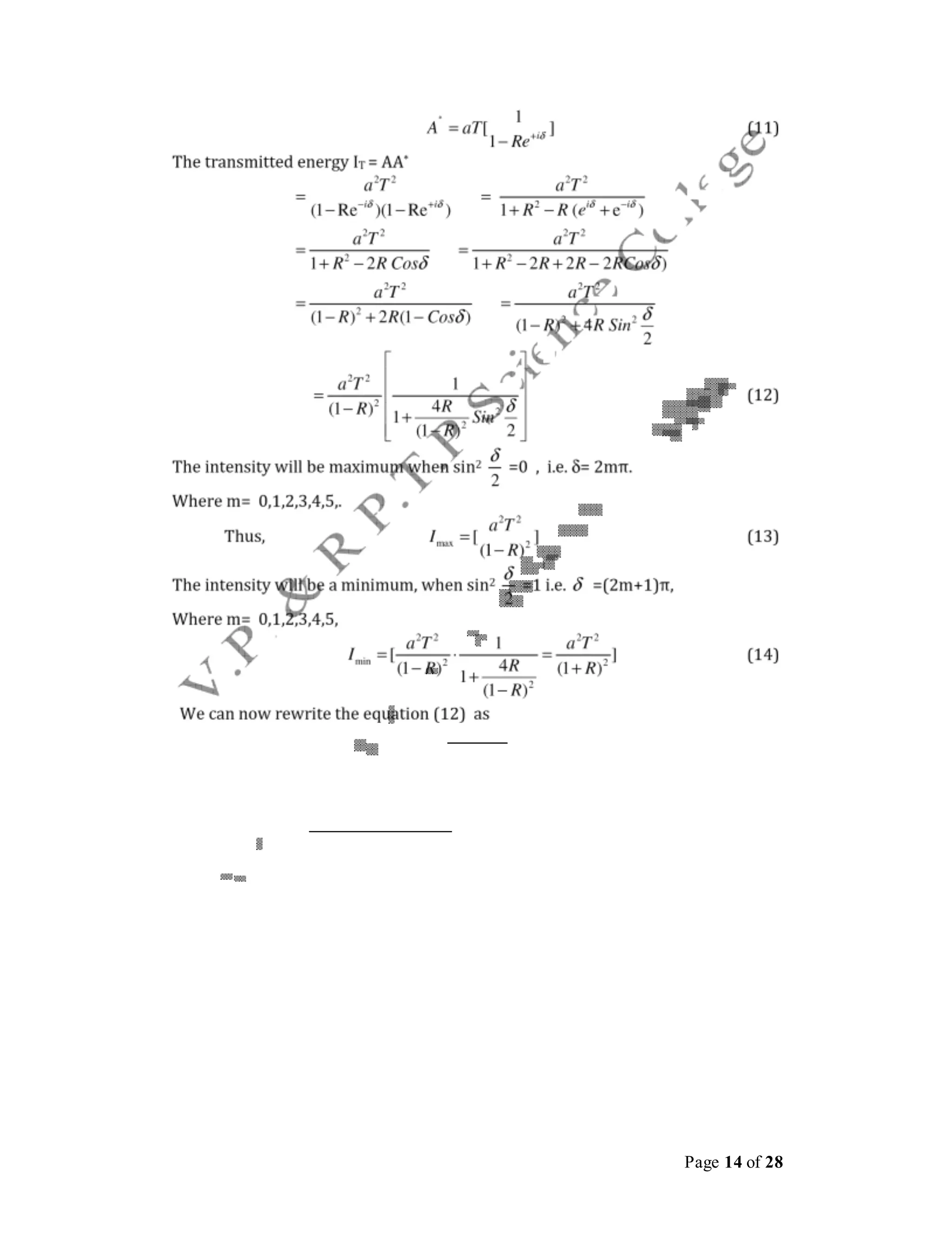
A=aT+aTRe−iδ
+aTR2e−2iδ
+aTR3e−3iδ
+...... (8)
A=aT[1+Re−iδ+R2e−2iδ+R3e−3iδ +......]
Using this expression for sum of the terms of a geometrical progression, we get
1−RNe−iNδ
A = aT −iδ (9)
1−Re
When the number of terms in the above expressionapproaches infinity,the term
RN
e−iNδ
tends to zero, and the transmitted amplitude reduces to
1
A=aT[ −iδ]
1−Re
The complex conjugate of A is givenby](https://image.slidesharecdn.com/us03cphy01unit2interferencediffractionpmp-210613193916/75/unit2-interference-amp-diffraction-13-2048.jpg)
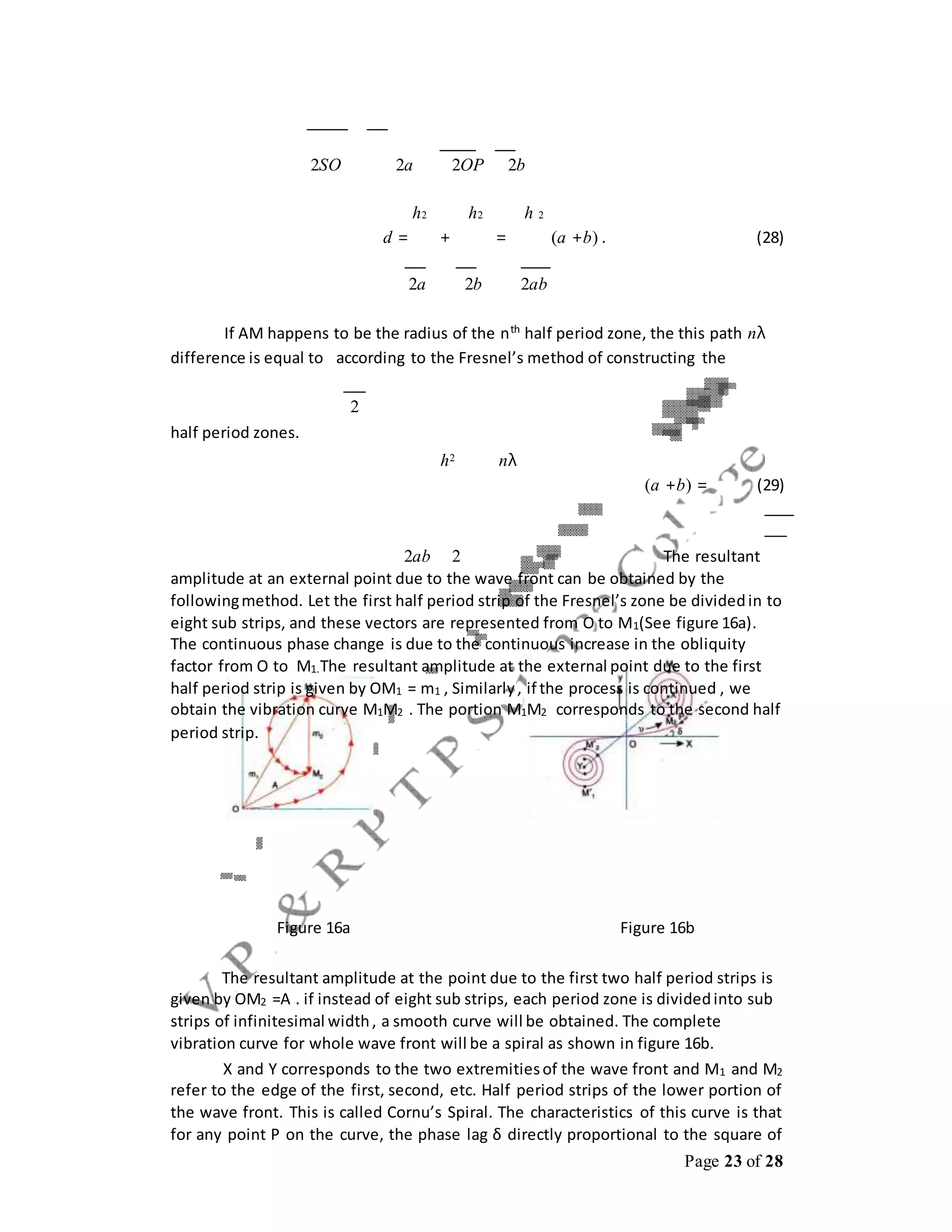
![Page 24 of 28
the v. The distance is measured along the length of the curve from the point O. For
oath difference of λ , the phase difference 2π. Hence, for a path difference of d , the
phase difference δ is given by
2π
δ= d (30)
λ
Substituting the value of d from equation 28, we get ,
π 2h2(a +b)
δ= [ ] (31)
2 abλ
π 2
δ= v (32)
2
The value of v is given by
2 2h2(a +b) 2(a + b)
v = or v = h (33)
abλ abλ
Cornu’s Spiral can be used for any diffraction problem irrespective of the values of a
,b and λ.
Fraunhoffer Diffraction
We have already seen about the Fraunhoffer diffraction and we also know
that in this type of diffraction, the source of light and the screen are effectively at
infinite distances from the obstacle. And we have also seen that this problem is
simple to handle mathematically because the rays are parallel. The incoming light is
rendered parallel with a lens and diffracted beam is focused on the screen with
another lens.
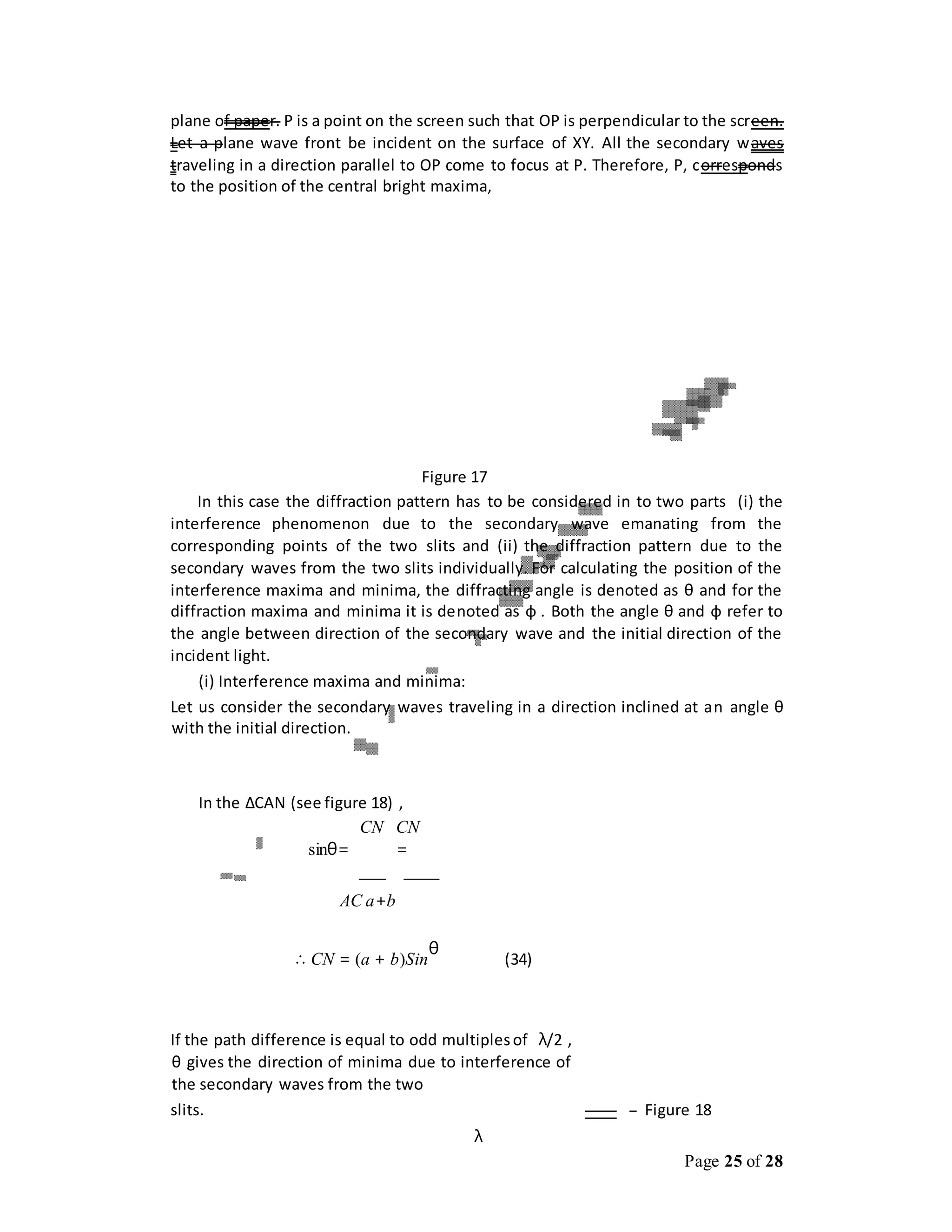
Fraunhoffer Diffraction at Double Slit:
In figure 17, AB and CD are two rectangular slits parallel to one another and
perpendicular to the plane of the paper. The width of each slit is a and the width of
opaque portion is b. L is a collecting lens and MN is a screen perpendicular to the](https://image.slidesharecdn.com/us03cphy01unit2interferencediffractionpmp-210613193916/75/unit2-interference-amp-diffraction-24-2048.jpg)


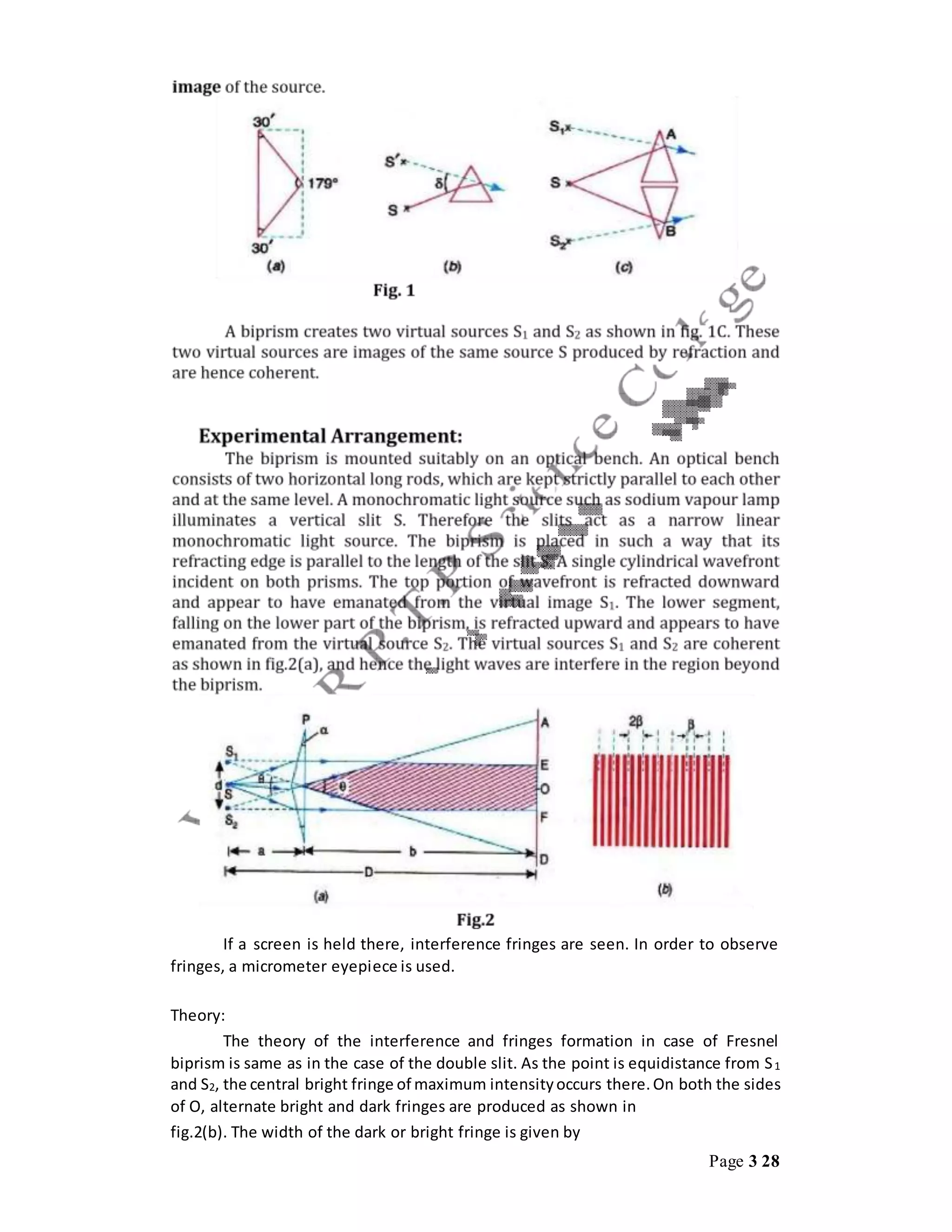
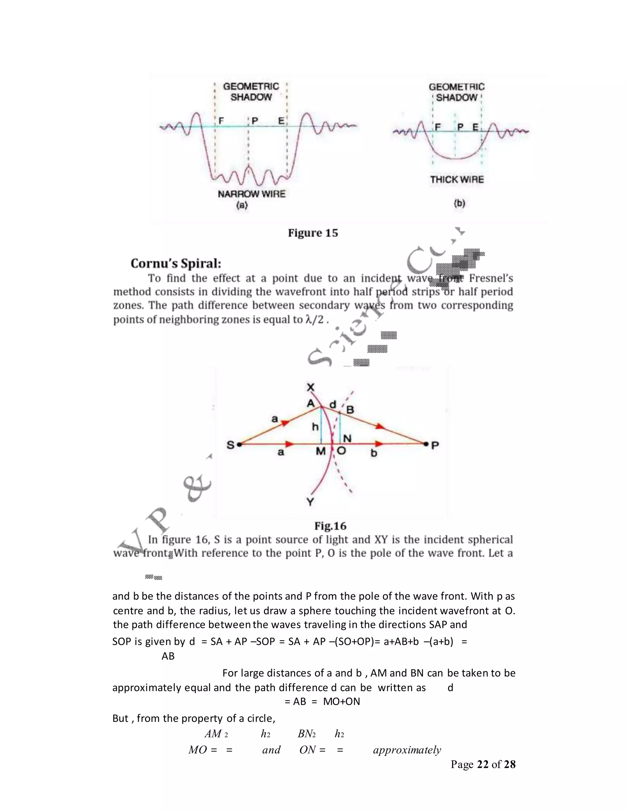
This document discusses interference and diffraction techniques in optics. It describes several methods for obtaining interference patterns, including wavefront splitting using devices like Young's double slits, and amplitude splitting using beam splitters. It then discusses several examples in more detail, including Fresnel's biprism, Lloyd's mirror, Newton's rings, and multiple beam interference in thin films. The key techniques discussed are used to determine the wavelength of light through measurement of fringe widths and distances.


