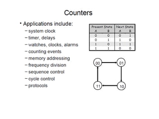
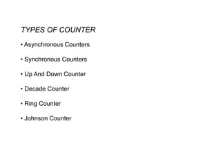
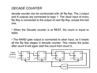
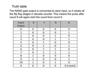
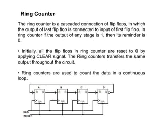
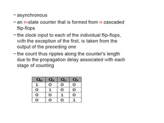
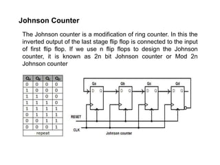
INTRODUCTION
Counters are the crucial hard ware components.
• Counter circuit are made using flip flop.
• Counters have modes. The ‘mod’ of the counter
represents the number of states of the cycles through it,
before setting the counter to its initial state.
• E.g A binary mod 4 counter has 4 count states, from
000 to 011. So the mod 4 counter counts from 0 to 4.
This means, in general a mod N counter can contain n
number of flip flops, where 2n = N.
WHAT IS COUNTER ?
The digital circuit which is used to count the number of pulses
are formly called the counter (Timers) .
A counter is a circuit that produces a numeric count each time
an input clock pulse makes an active transition
Counting means incrementing or decrementing the values of an
operator, with respect to its previous state value. We cannot
perform this action (counting) with any other logic devices rather
than counters.
TYPES OF COUNTER
• Asynchronous Counters
• Synchronous Counters
• Up And Down Counter
• Decade Counter
• Ring Counter
• Johnson Counter
DIFFERENCE
SYNCHRONOUs
• The propagation delay is very low.
• Its operational frequency is very
high.
• These are faster than that of ripple
counters.
• Large number of logic gates are
required to design
• High cost.
• Synchronous circuits are easy to
design
ASYNCHRONOUS
• Propagation delay is higher
than that of synchronous
counters.
• The maximum frequency of
operation is very low.
• These are slow in operation.
• Less number of logic gates
required.
• Low cost.
• Complex to design.
ASYNCHRONOUS UP/DOWN COUNTER
The asynchronous is the simplest in term of logical
operation there for it is easiest to design.
• Here the clock pulse is applied to first flip flop and the
successesive f/f are triggerd by the output of the previous
out put thus the counter has the cumulative settling time
Truth table for up/down counter
DECADE COUNTER
decade counter can be constructed with JK flip flop. The J output
and K outputs are connected to logic 1. The clock input of every
flip flop is connected to the output of next flip flop, except the last
one.
• When the Decade counter is at REST, the count is equal to
0000.
• The NAND gate output is connected to clear input, so it resets
all the flip flop stages in decade counter. This means the pulse
after count 9 will again start the count from count 0.
Truth table
The NAND gate output is connected to clear input, so it resets all
the flip flop stages in decade counter. This means the pulse after
count 9 will again start the count from count 0.
Ring Counter
The ring counter is a cascaded connection of flip flops, in which
the output of last flip flop is connected to input of first flip flop. In
ring counter if the output of any stage is 1, then its reminder is
0.
• Initially, all the flip flops in ring counter are reset to 0 by
applying CLEAR signal. The Ring counters transfers the same
output throughout the circuit.
• Ring counters are used to count the data in a continuous
loop.
Johnson Counter
The Johnson counter is a modification of ring counter. In this the
inverted output of the last stage flip flop is connected to the input
of first flip flop. If we use n flip flops to design the Johnson
counter, it is known as 2n bit Johnson counter or Mod 2n
Johnson counter

counters.ppt

  • 1.
    INTRODUCTION Counters are thecrucial hard ware components. • Counter circuit are made using flip flop. • Counters have modes. The ‘mod’ of the counter represents the number of states of the cycles through it, before setting the counter to its initial state. • E.g A binary mod 4 counter has 4 count states, from 000 to 011. So the mod 4 counter counts from 0 to 4. This means, in general a mod N counter can contain n number of flip flops, where 2n = N.
  • 2.
    WHAT IS COUNTER? The digital circuit which is used to count the number of pulses are formly called the counter (Timers) . A counter is a circuit that produces a numeric count each time an input clock pulse makes an active transition Counting means incrementing or decrementing the values of an operator, with respect to its previous state value. We cannot perform this action (counting) with any other logic devices rather than counters.
  • 4.
    TYPES OF COUNTER •Asynchronous Counters • Synchronous Counters • Up And Down Counter • Decade Counter • Ring Counter • Johnson Counter
  • 5.
    DIFFERENCE SYNCHRONOUs • The propagationdelay is very low. • Its operational frequency is very high. • These are faster than that of ripple counters. • Large number of logic gates are required to design • High cost. • Synchronous circuits are easy to design ASYNCHRONOUS • Propagation delay is higher than that of synchronous counters. • The maximum frequency of operation is very low. • These are slow in operation. • Less number of logic gates required. • Low cost. • Complex to design.
  • 6.
    ASYNCHRONOUS UP/DOWN COUNTER Theasynchronous is the simplest in term of logical operation there for it is easiest to design. • Here the clock pulse is applied to first flip flop and the successesive f/f are triggerd by the output of the previous out put thus the counter has the cumulative settling time
  • 7.
    Truth table forup/down counter
  • 8.
    DECADE COUNTER decade countercan be constructed with JK flip flop. The J output and K outputs are connected to logic 1. The clock input of every flip flop is connected to the output of next flip flop, except the last one. • When the Decade counter is at REST, the count is equal to 0000. • The NAND gate output is connected to clear input, so it resets all the flip flop stages in decade counter. This means the pulse after count 9 will again start the count from count 0.
  • 9.
    Truth table The NANDgate output is connected to clear input, so it resets all the flip flop stages in decade counter. This means the pulse after count 9 will again start the count from count 0.
  • 10.
    Ring Counter The ringcounter is a cascaded connection of flip flops, in which the output of last flip flop is connected to input of first flip flop. In ring counter if the output of any stage is 1, then its reminder is 0. • Initially, all the flip flops in ring counter are reset to 0 by applying CLEAR signal. The Ring counters transfers the same output throughout the circuit. • Ring counters are used to count the data in a continuous loop.
  • 12.
    Johnson Counter The Johnsoncounter is a modification of ring counter. In this the inverted output of the last stage flip flop is connected to the input of first flip flop. If we use n flip flops to design the Johnson counter, it is known as 2n bit Johnson counter or Mod 2n Johnson counter