SlideShare a Scribd company logo
1 of 9
ITT TECH
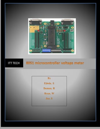
A simple 0-5V voltmeter using 8051 is shown in this article. This digital voltmeter
has a sensitivity of 200mV which is a bit low but this project is meant for
demonstrating how an ADC and seven segment display can be interfaced to 8051
to obtain a digital readout of the input voltage. A 31/2 digit high end voltmeter will
be added soon. ADC0804 is the ADC and AT89S51 is the controller used in this
project. Before attempting this project, go through these projects Interfacing ADC
to 8051 and Interfacing seven segment displays to 8051 which will give you a
good idea on the basics.
About the circuit
In the circuit Vref/2 (pin9) of the ADC is left open and it means that the input
voltage span can be o to 5V and the step size will be 5/255 = 19.6mV. The
equation for the digital output of ADC0804 is Dout = Vin/Step size. In this circuit,
for an input voltage of 1V the digital output will be 1/19.6mV = 51 and so the
binary equivalent of 51 i.e. 00110011. Digital output of the ADC is interfaced to
P1.0 of the microcontroller. Controlsignals for the ADC i.e. CS, RD, WR and
INTR are available from the P3.7, P3.6, P3.5 and P3.4 pins of the microcontroller
respectively. 2 digit multiplexed seven segment display is interfaced to Port0 of the
microcontroller. Control signals for the display driver transistors Q1 and Q2 are
obtained from P3.2 and P3.1 of the microcontroller. Push button switch S1,
capacitor C2 and resistor R10 forms a de-bouncing reset circuitry.
About the program
At first the program controls the ADC to producea digital output correspondingto
the input voltage. This digital output is scanned through P1.0 and is loaded to
accumulator. Then the value in the accumulator is divided by 10 to omit the last
digit. Forexample, let the input voltage be 4V. Then the corresponding digital
output of the ADC will be 204D (D stands for decimal) .After the division by 10,
the value left in the accumulator will be 20D. This 20D is then multiplied by 2D
which results in 40D. The next target of the program is to manipulate this 40D and
make 4.0 read-out on the display. For this the 40D is again divided by 10D. This
results in 4 inside accumulator and 0 inside B register. Then the program gets the
digit drive pattern for 4 using the lookup table, puts this pattern on Port 0 and
activates Q1. After 1 ms delay 10000000B is loaded to P0 and this accounts for the
dot. After a further 1ms delay Q1 is deactivated, content in B (i.e. 0) is moved to
A, gets the correct digit drive pattern for 0 using the lookup table, puts this pattern
on Port 0 and activates Q2. After a further 1ms delay Q2 is deactivated and the
entire cycle is repeated.
Program
ORG 00H
MOV P1, #11111111B
MOV P0, #00000000B
MOV P3, #00000000B
MOV DPTR, #LABEL
MAIN: CLR P3.7
SETB P3.6
CLR P3.5
SETB P3.5
WAIT: JB P3.4, WAIT
CLR P3.7
CLR P3.6
MOV A, P1
MOV B, #10D
DIV AB
MOV B, #2D
MUL AB
MOV B, #10D
DIV AB
SETB P3.2
ACALL DISPLAY
MOV P0, A
ACALL DELAY
MOV P0, #10000000B
ACALL DELAY
MOV A, B
CLR P3.2
SETB P3.1
ACALL DISPLAY
MOV P0, A
ACALL DELAY
CLR P3.1
SJMP MAIN
DELAY: MOV R3, #02H
DEL1: MOV R2, #0FAH
DEL2: DJNZ R2, DEL2
DJNZ R3, DEL1
RET
DISPLAY: MOVC A,@A+DPTR
RET
LABEL: DB 3FH
DB 06H
DB 5BH
DB 4FH
DB 66H
DB 6DH
DB 7DH
DB 07H
DB 7FH
DB 6FH
END
Measure Voltages with an 8051 Microcontroller and ADC0804

More Related Content

What's hot

Ee2 chapter14 ic_counters
Ee2 chapter14 ic_countersEe2 chapter14 ic_counters
Ee2 chapter14 ic_countersCK Yang
 
Digital Counter Design
 Digital Counter Design Digital Counter Design
Digital Counter DesignGargiKhanna1
 
Digital clock
Digital clockDigital clock
Digital clockAbi Malik
 
Interfacing technique with 8085- ADC[0808]
Interfacing technique with 8085- ADC[0808]Interfacing technique with 8085- ADC[0808]
Interfacing technique with 8085- ADC[0808]Guhan k
 
Digital clock (mod counters)using DSCH (DIGITAL SCHEMATIC) by Gaurav Raikar
Digital clock (mod counters)using DSCH (DIGITAL SCHEMATIC) by Gaurav RaikarDigital clock (mod counters)using DSCH (DIGITAL SCHEMATIC) by Gaurav Raikar
Digital clock (mod counters)using DSCH (DIGITAL SCHEMATIC) by Gaurav RaikarGauravRaikar3
 
15CS32 ADE Module 5
15CS32 ADE Module 515CS32 ADE Module 5
15CS32 ADE Module 5RLJIT
 
Datasheet
DatasheetDatasheet
Datasheetjuan
 
Digital Clock Using Logic Gates
Digital Clock Using Logic GatesDigital Clock Using Logic Gates
Digital Clock Using Logic GatesJalpaMaheshwari1
 
Eceg 3201-dld-lec 12-synchronous_counter_design
Eceg 3201-dld-lec 12-synchronous_counter_designEceg 3201-dld-lec 12-synchronous_counter_design
Eceg 3201-dld-lec 12-synchronous_counter_designNebiyu Musie
 
555 timer-digital-clock
555 timer-digital-clock555 timer-digital-clock
555 timer-digital-clockGaditek
 
DELD Unit IV ring and twisted ring counter
DELD Unit IV ring and twisted ring counterDELD Unit IV ring and twisted ring counter
DELD Unit IV ring and twisted ring counterKanchanPatil34
 

What's hot (20)

Ee2 chapter14 ic_counters
Ee2 chapter14 ic_countersEe2 chapter14 ic_counters
Ee2 chapter14 ic_counters
 
Chapter 5 counter
Chapter 5 counterChapter 5 counter
Chapter 5 counter
 
Digital Counter Design
 Digital Counter Design Digital Counter Design
Digital Counter Design
 
Ece221 Ch7 Part1
Ece221 Ch7 Part1Ece221 Ch7 Part1
Ece221 Ch7 Part1
 
Digital clock
Digital clockDigital clock
Digital clock
 
Interfacing technique with 8085- ADC[0808]
Interfacing technique with 8085- ADC[0808]Interfacing technique with 8085- ADC[0808]
Interfacing technique with 8085- ADC[0808]
 
Synchronous Counter
Synchronous Counter Synchronous Counter
Synchronous Counter
 
G. ripple counter
G. ripple counterG. ripple counter
G. ripple counter
 
Digital clock (mod counters)using DSCH (DIGITAL SCHEMATIC) by Gaurav Raikar
Digital clock (mod counters)using DSCH (DIGITAL SCHEMATIC) by Gaurav RaikarDigital clock (mod counters)using DSCH (DIGITAL SCHEMATIC) by Gaurav Raikar
Digital clock (mod counters)using DSCH (DIGITAL SCHEMATIC) by Gaurav Raikar
 
Digital Clock
Digital ClockDigital Clock
Digital Clock
 
Dee2034 chapter 5 counter
Dee2034 chapter 5 counterDee2034 chapter 5 counter
Dee2034 chapter 5 counter
 
15CS32 ADE Module 5
15CS32 ADE Module 515CS32 ADE Module 5
15CS32 ADE Module 5
 
Datasheet
DatasheetDatasheet
Datasheet
 
decade counter
decade counterdecade counter
decade counter
 
Digital Clock Using Logic Gates
Digital Clock Using Logic GatesDigital Clock Using Logic Gates
Digital Clock Using Logic Gates
 
77
7777
77
 
8051 interfacing
8051 interfacing8051 interfacing
8051 interfacing
 
Eceg 3201-dld-lec 12-synchronous_counter_design
Eceg 3201-dld-lec 12-synchronous_counter_designEceg 3201-dld-lec 12-synchronous_counter_design
Eceg 3201-dld-lec 12-synchronous_counter_design
 
555 timer-digital-clock
555 timer-digital-clock555 timer-digital-clock
555 timer-digital-clock
 
DELD Unit IV ring and twisted ring counter
DELD Unit IV ring and twisted ring counterDELD Unit IV ring and twisted ring counter
DELD Unit IV ring and twisted ring counter
 

Viewers also liked

Aiwa nsx k750
Aiwa nsx k750Aiwa nsx k750
Aiwa nsx k750ironmikep
 
3A Profile 1 Complete
3A Profile 1 Complete3A Profile 1 Complete
3A Profile 1 CompleteAamir Latif
 
853d2d6cb078f2bc22f052891402e306
853d2d6cb078f2bc22f052891402e306853d2d6cb078f2bc22f052891402e306
853d2d6cb078f2bc22f052891402e306howcyong1011
 
The Curti Spacesaver
The Curti SpacesaverThe Curti Spacesaver
The Curti SpacesaverLisa Emsley
 
Barrow presentation pp
Barrow presentation ppBarrow presentation pp
Barrow presentation ppCara Gibson
 
DIGITAL VOLTMETER USING 8051 MICROCONTROLLER
DIGITAL VOLTMETER USING 8051 MICROCONTROLLERDIGITAL VOLTMETER USING 8051 MICROCONTROLLER
DIGITAL VOLTMETER USING 8051 MICROCONTROLLERChirag Lakhani
 
Construction of digital voltmeter by Bapi Kumar Das
Construction of digital voltmeter by Bapi Kumar DasConstruction of digital voltmeter by Bapi Kumar Das
Construction of digital voltmeter by Bapi Kumar DasB.k. Das
 

Viewers also liked (16)

Digital voltmeter
Digital voltmeterDigital voltmeter
Digital voltmeter
 
Webwersion intensitet ed
Webwersion intensitet edWebwersion intensitet ed
Webwersion intensitet ed
 
Aiwa nsx k750
Aiwa nsx k750Aiwa nsx k750
Aiwa nsx k750
 
3A Profile 1 Complete
3A Profile 1 Complete3A Profile 1 Complete
3A Profile 1 Complete
 
853d2d6cb078f2bc22f052891402e306
853d2d6cb078f2bc22f052891402e306853d2d6cb078f2bc22f052891402e306
853d2d6cb078f2bc22f052891402e306
 
Analandia
AnalandiaAnalandia
Analandia
 
The Curti Spacesaver
The Curti SpacesaverThe Curti Spacesaver
The Curti Spacesaver
 
NZEUKWU CHIJIOKE JOHN cv {updated}
NZEUKWU CHIJIOKE JOHN cv {updated}NZEUKWU CHIJIOKE JOHN cv {updated}
NZEUKWU CHIJIOKE JOHN cv {updated}
 
Barrow presentation pp
Barrow presentation ppBarrow presentation pp
Barrow presentation pp
 
Digital voltmeter project
Digital voltmeter projectDigital voltmeter project
Digital voltmeter project
 
DIGITAL VOLTMETER USING 8051 MICROCONTROLLER
DIGITAL VOLTMETER USING 8051 MICROCONTROLLERDIGITAL VOLTMETER USING 8051 MICROCONTROLLER
DIGITAL VOLTMETER USING 8051 MICROCONTROLLER
 
Construction of digital voltmeter by Bapi Kumar Das
Construction of digital voltmeter by Bapi Kumar DasConstruction of digital voltmeter by Bapi Kumar Das
Construction of digital voltmeter by Bapi Kumar Das
 
Voltmeter
VoltmeterVoltmeter
Voltmeter
 
Ammeter
AmmeterAmmeter
Ammeter
 
Digital voltmeter
Digital voltmeterDigital voltmeter
Digital voltmeter
 
Slideshare ppt
Slideshare pptSlideshare ppt
Slideshare ppt
 

Similar to Measure Voltages with an 8051 Microcontroller and ADC0804

adcanddac hai kya bhayy me know if-01.pptx
adcanddac hai kya bhayy me know if-01.pptxadcanddac hai kya bhayy me know if-01.pptx
adcanddac hai kya bhayy me know if-01.pptxshivraj3252
 
digitalvoltmeterusing805112b2-170214173216 (1).pdf
digitalvoltmeterusing805112b2-170214173216 (1).pdfdigitalvoltmeterusing805112b2-170214173216 (1).pdf
digitalvoltmeterusing805112b2-170214173216 (1).pdfsatyamsinha37
 
analog to digital converter and dac final
analog to digital converter and dac finalanalog to digital converter and dac final
analog to digital converter and dac finalDrVikasMahor
 
Unit iv microcontrollers final
Unit iv microcontrollers finalUnit iv microcontrollers final
Unit iv microcontrollers finalSARITHA REDDY
 
Lab 9 D-Flip Flops: Shift Register and Sequence Counter
Lab 9 D-Flip Flops: Shift Register and Sequence CounterLab 9 D-Flip Flops: Shift Register and Sequence Counter
Lab 9 D-Flip Flops: Shift Register and Sequence CounterKatrina Little
 
Analog to Digital Converters
Analog to Digital ConvertersAnalog to Digital Converters
Analog to Digital ConvertersAmitabh Shukla
 
ADC and DAC interfacing.pdf
ADC and DAC interfacing.pdfADC and DAC interfacing.pdf
ADC and DAC interfacing.pdfVikasMahor3
 
Digital voltmeter using 89c51 microcontroller
Digital voltmeter using 89c51 microcontrollerDigital voltmeter using 89c51 microcontroller
Digital voltmeter using 89c51 microcontrollerSaylee joshi
 
Adc by anil kr yadav
Adc by anil kr yadavAdc by anil kr yadav
Adc by anil kr yadavAnil Yadav
 
ANALOG TO DIGITAL CONVERTOR
ANALOG TO DIGITAL CONVERTORANALOG TO DIGITAL CONVERTOR
ANALOG TO DIGITAL CONVERTORAnil Yadav
 
lab_ADC.pdf
lab_ADC.pdflab_ADC.pdf
lab_ADC.pdfboukomra
 
Microprocessor based Temperature Controller
Microprocessor based Temperature ControllerMicroprocessor based Temperature Controller
Microprocessor based Temperature ControllerRevanth Reddy
 
Analog To Digital Conversion (ADC) Programming in LPC2148
Analog To Digital Conversion (ADC) Programming in LPC2148Analog To Digital Conversion (ADC) Programming in LPC2148
Analog To Digital Conversion (ADC) Programming in LPC2148Omkar Rane
 

Similar to Measure Voltages with an 8051 Microcontroller and ADC0804 (20)

Chapter5 dek3133
Chapter5 dek3133Chapter5 dek3133
Chapter5 dek3133
 
adcanddac hai kya bhayy me know if-01.pptx
adcanddac hai kya bhayy me know if-01.pptxadcanddac hai kya bhayy me know if-01.pptx
adcanddac hai kya bhayy me know if-01.pptx
 
Adc interfacing
Adc interfacingAdc interfacing
Adc interfacing
 
digitalvoltmeterusing805112b2-170214173216 (1).pdf
digitalvoltmeterusing805112b2-170214173216 (1).pdfdigitalvoltmeterusing805112b2-170214173216 (1).pdf
digitalvoltmeterusing805112b2-170214173216 (1).pdf
 
analog to digital converter and dac final
analog to digital converter and dac finalanalog to digital converter and dac final
analog to digital converter and dac final
 
Unit iv microcontrollers final
Unit iv microcontrollers finalUnit iv microcontrollers final
Unit iv microcontrollers final
 
Lab 9 D-Flip Flops: Shift Register and Sequence Counter
Lab 9 D-Flip Flops: Shift Register and Sequence CounterLab 9 D-Flip Flops: Shift Register and Sequence Counter
Lab 9 D-Flip Flops: Shift Register and Sequence Counter
 
Analog to Digital Converters
Analog to Digital ConvertersAnalog to Digital Converters
Analog to Digital Converters
 
Anup2
Anup2Anup2
Anup2
 
8255
82558255
8255
 
ADC and DAC interfacing.pdf
ADC and DAC interfacing.pdfADC and DAC interfacing.pdf
ADC and DAC interfacing.pdf
 
ADC and DAC Best Ever Pers
ADC and DAC Best Ever PersADC and DAC Best Ever Pers
ADC and DAC Best Ever Pers
 
Digital voltmeter using 89c51 microcontroller
Digital voltmeter using 89c51 microcontrollerDigital voltmeter using 89c51 microcontroller
Digital voltmeter using 89c51 microcontroller
 
Adc by anil kr yadav
Adc by anil kr yadavAdc by anil kr yadav
Adc by anil kr yadav
 
ANALOG TO DIGITAL CONVERTOR
ANALOG TO DIGITAL CONVERTORANALOG TO DIGITAL CONVERTOR
ANALOG TO DIGITAL CONVERTOR
 
lab_ADC.pdf
lab_ADC.pdflab_ADC.pdf
lab_ADC.pdf
 
Microprocessor based Temperature Controller
Microprocessor based Temperature ControllerMicroprocessor based Temperature Controller
Microprocessor based Temperature Controller
 
Adc and dac
Adc and dacAdc and dac
Adc and dac
 
8155 GPPI
8155 GPPI8155 GPPI
8155 GPPI
 
Analog To Digital Conversion (ADC) Programming in LPC2148
Analog To Digital Conversion (ADC) Programming in LPC2148Analog To Digital Conversion (ADC) Programming in LPC2148
Analog To Digital Conversion (ADC) Programming in LPC2148
 

Measure Voltages with an 8051 Microcontroller and ADC0804

  • 2. A simple 0-5V voltmeter using 8051 is shown in this article. This digital voltmeter has a sensitivity of 200mV which is a bit low but this project is meant for demonstrating how an ADC and seven segment display can be interfaced to 8051 to obtain a digital readout of the input voltage. A 31/2 digit high end voltmeter will be added soon. ADC0804 is the ADC and AT89S51 is the controller used in this project. Before attempting this project, go through these projects Interfacing ADC to 8051 and Interfacing seven segment displays to 8051 which will give you a good idea on the basics. About the circuit In the circuit Vref/2 (pin9) of the ADC is left open and it means that the input voltage span can be o to 5V and the step size will be 5/255 = 19.6mV. The equation for the digital output of ADC0804 is Dout = Vin/Step size. In this circuit, for an input voltage of 1V the digital output will be 1/19.6mV = 51 and so the binary equivalent of 51 i.e. 00110011. Digital output of the ADC is interfaced to P1.0 of the microcontroller. Controlsignals for the ADC i.e. CS, RD, WR and INTR are available from the P3.7, P3.6, P3.5 and P3.4 pins of the microcontroller respectively. 2 digit multiplexed seven segment display is interfaced to Port0 of the microcontroller. Control signals for the display driver transistors Q1 and Q2 are obtained from P3.2 and P3.1 of the microcontroller. Push button switch S1, capacitor C2 and resistor R10 forms a de-bouncing reset circuitry. About the program At first the program controls the ADC to producea digital output correspondingto the input voltage. This digital output is scanned through P1.0 and is loaded to accumulator. Then the value in the accumulator is divided by 10 to omit the last digit. Forexample, let the input voltage be 4V. Then the corresponding digital output of the ADC will be 204D (D stands for decimal) .After the division by 10, the value left in the accumulator will be 20D. This 20D is then multiplied by 2D which results in 40D. The next target of the program is to manipulate this 40D and make 4.0 read-out on the display. For this the 40D is again divided by 10D. This results in 4 inside accumulator and 0 inside B register. Then the program gets the digit drive pattern for 4 using the lookup table, puts this pattern on Port 0 and activates Q1. After 1 ms delay 10000000B is loaded to P0 and this accounts for the
  • 3. dot. After a further 1ms delay Q1 is deactivated, content in B (i.e. 0) is moved to A, gets the correct digit drive pattern for 0 using the lookup table, puts this pattern on Port 0 and activates Q2. After a further 1ms delay Q2 is deactivated and the entire cycle is repeated. Program ORG 00H MOV P1, #11111111B MOV P0, #00000000B MOV P3, #00000000B MOV DPTR, #LABEL MAIN: CLR P3.7 SETB P3.6 CLR P3.5 SETB P3.5 WAIT: JB P3.4, WAIT CLR P3.7 CLR P3.6 MOV A, P1 MOV B, #10D DIV AB MOV B, #2D MUL AB MOV B, #10D
  • 4. DIV AB SETB P3.2 ACALL DISPLAY MOV P0, A ACALL DELAY MOV P0, #10000000B ACALL DELAY MOV A, B CLR P3.2 SETB P3.1 ACALL DISPLAY MOV P0, A ACALL DELAY CLR P3.1 SJMP MAIN DELAY: MOV R3, #02H DEL1: MOV R2, #0FAH DEL2: DJNZ R2, DEL2 DJNZ R3, DEL1 RET DISPLAY: MOVC A,@A+DPTR RET LABEL: DB 3FH
  • 5. DB 06H DB 5BH DB 4FH DB 66H DB 6DH DB 7DH DB 07H DB 7FH DB 6FH END