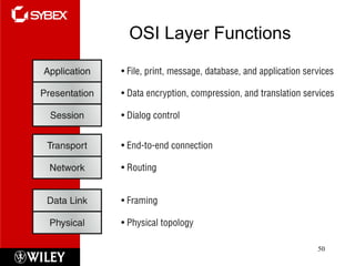
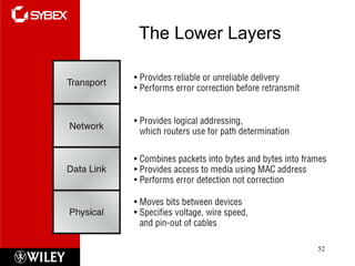
Click to edit Master subtitle style Todd Lammle’s CompTIA Network+ Chapter 2: OSI Specifications Instructor: Mike Qaissaunee
Chapter 2 Objectives The Following CompTIA Network+ Exam Objectives Are Covered in This Chapter:  4.1 Explain the function of each layer of the OSI model Layer 1 – physical Layer 2 – data link Layer 3 – network Layer 4 – transport Layer 5 – session Layer 6 – presentation Layer 7 – application
Networking Standards Organizations Standard Documented agreement Technical specifications/precise criteria Stipulates design or performance of particular product or service Standards are essential in the networking world Wide variety of hardware and software Ensures network design compatibility Standards define minimum acceptable performance Not ideal performance
Networking Standards Organizations (cont’d.) Many different organizations oversee computer industry standards Organizations may overlap responsibilities Example: ANSI and IEEE set wireless standards Network professional’s responsibility Be familiar with groups setting networking standards Understand critical aspects of standards required by own networks
ANSI ANSI (American National Standards Institute) 1000+ representatives from industry and government Determines standards for electronics industry and other fields, such as chemical and nuclear engineering, health and safety, and construction.  Requests voluntarily compliance with standards Obtaining ANSI approval requires rigorous testing ANSI standards documents available online at www.ansi.org
EIA and TIA EIA (Electronic Industries Alliance) Trade organization Representatives from United States electronics manufacturing firms Sets standards for its members Helps write ANSI standards Lobbies for favorable computer and electronics industries legislation Sponsor conferences, exhibitions, and forums in their areas of interest
EIA and TIA (cont’d.) TIA (Telecommunications Industry Association) Formed in 1988 EIA subgroup merged with former United States Telecommunications Suppliers Association (USTSA) Focus of TIA Standards for information technology, wireless, satellite, fiber optics, and telephone equipment TIA/EIA 568-B Series Guidelines for installing network cable in commercial buildings
IEEE IEEE (Institute of Electrical and Electronics Engineers) International engineering professionals society Goal of IEEE Promote development and education in electrical engineering and computer science fields Hosts symposia, conferences, and chapter meetings Maintains a standards board IEEE technical papers and standards Highly respected
ISO ISO (International Organization for Standardization) Headquartered in Geneva, Switzerland Collection of standards organizations Representing 57 countries Goal of ISO  Establish international technological standards to facilitate global exchange of information and barrier free trade Widespread authority
ITU ITU (International Telecommunication Union) Specialized United Nations agency Regulates international telecommunications Provides developing countries with technical expertise and equipment Founded in 1865 Joined United Nations in 1947 Members from 191 countries Focus of ITU Global telecommunications issues Worldwide Internet services implementation
ISOC ISOC (Internet Society) Founded in 1992 Professional membership society ISOC’s membership consists of thousands of Internet professionals and companies from 90 chapters around the world  Establishes technical Internet standards Current ISOC concerns Rapid Internet growth Keeping Internet accessible Information security Stable Internet addressing services Open standards
ISOC (cont’d.) ISOC oversees groups with specific missions IAB (Internet Architecture Board) Technical advisory group Overseeing Internet’s design and management IETF (Internet Engineering Task Force) Sets Internet system communication standards Particularly protocol operation and interaction Anyone may submit standard proposal Elaborate review, testing, and approval processes IETF works with the ITU to help give technical standards approved in the United States international acceptance
IANA and ICANN IP (Internet Protocol) address Address identifying computers in TCP/IP based (Internet) networks Reliance on centralized management authorities IP address management history In early Internet history, a nonprofit group called the IANA ( Internet Assigned Numbers Authority) kept records of available and reserved IP addresses and determined how addresses were doled out Starting in 1997, IANA coordinated its efforts with three RIRs ( Regional Inter-net Registries): ARIN ( American Registry for Internet Numbers), APNIC ( Asia Pacific Network Information Centre), and RIPE ( Réseaux IP Européens)
IANA and ICANN (cont’d.) In the late 1990s, the United States Department of Commerce ( DOC), which funded IANA, decided to overhaul IP addressing and domain name management The DOC recommended the formation of ICANN ( Internet Corporation for Assigned Names and Numbers), a private, nonprofit corporation. ICANN is now ultimately responsible for IP addressing and domain name management  Users and business obtain IP addresses from ISP (Internet service provider) You can learn more about IANA and ICANN at their Web sites, www iana.org and www.icann.org
Quick Quiz  True or False: Standards define maximum acceptable performance  Answer:  False True or False: Standards help to ensure interoperability between software and hardware from different manufacturers Answer:  True Which standards organization requests voluntary compliance with their standards? IANA ISO ITU ANSI
Internetworking Models In the late 1970s, the  Open Systems Interconnection (OSI) reference model  was created by the International Organization for Standardization (ISO) to break through this barrier. The OSI model was meant to help vendors create interoperable network devices and software in the form of protocols so that different vendor networks could work with each other.  The OSI model is the primary architectural model for networks. It describes how data and network information are communicated from an application on one computer through the network media to an application on another computer. The OSI reference model breaks this approach into layers.
Advantages of Reference Models Advantages of using the OSI layered model include, but are not limited to, the following: It divides the network communication process into smaller and simpler components, thus aiding component development, design, and troubleshooting. It allows multiple-vendor development through standardization of network components. It encourages industry standardization by defining what functions occur at each layer of the model. It allows various types of network hardware and software to communicate. It prevents changes in one layer from affecting other layers, so it doesn’t hamper development and makes application programming easier.
The OSI Model The OSI model has seven layers:  Application (Layer 7) Presentation (Layer 6) Session (Layer 5) Transport (Layer 4) Network (Layer 3) Data Link (Layer 2) Physical (Layer 1)
The OSI Model Model for understanding and developing network computer-to-computer communications Developed by ISO (1980s) Divides network communications into seven layers Physical, Data Link, Network, Transport, Session, Presentation, Application
The OSI Model (cont’d.) Protocol interaction Layer directly above and below Application layer protocols Interact with software Physical layer protocols Act on cables and connectors
The OSI Model (cont’d.) Theoretical representation describing network communication between two nodes Hardware and software independent Every network communication process represented PDUs (protocol data units) Discrete amount of data Application layer function Flow through layers 6, 5, 4, 3, 2, and 1 Generalized model and sometime imperfect
Figure 2.1 Flow of data through the OSI model
Application Layer Top (seventh) OSI model layer No software applications Protocol functions Facilitates communication Between software applications and lower-layer network services Network interprets application request Application interprets data sent from network Software applications negotiate with application layer protocols
Presentation Layer Protocol functions Accept Application layer data Format data Understandable to different applications and hosts Example: text encoding methods Presentation layer protocols perform coding and compression Example: Presentation layer services manage data encryption and decryption
Session Layer Protocol functions Coordinate and maintain communications between two nodes Session  Connection for ongoing data exchange between two parties Connection between remote client and access server Connection between Web browser client and Web server
Session Layer (cont’d.) Functions Establishing and keeping alive communications link For session duration Keeping communications secure Synchronizing dialogue between two nodes Determining if communications ended Determining where to restart transmission Terminating communications
Transport Layer Protocol functions Accept data from Session layer Manage end-to-end data delivery Handle flow control Connection-oriented protocols Establish connection before transmitting data Checksum Unique character string allowing receiving node to determine if arriving data unit exactly matches data unit sent by source Further ensures data integrity
Transport Layer (cont’d.) Connectionless protocols Do not establish connection with another node before transmitting data Make no effort to ensure data is delivered free of errors More efficient than connection-oriented protocol Useful when data must be transferred quickly Segmentation Breaking large data units received from Session layer into multiple smaller units called segments Increases data transmission efficiency
Reliability Reliable data transport employs a connection-oriented communications session between systems, and the protocols involved ensure that the following will be achieved: The segments delivered are acknowledged back to the sender upon their reception. Any segments not acknowledged are retransmitted. Segments are sequenced back into their proper order upon arrival at their destination. A manageable data flow is maintained in order to avoid congestion, overloading, and data loss.
A Connection Oriented Session at Layer 4
Flow Control at Layer 4
Windowing Flow Control
Acknowledgements
Transport Layer (cont’d.) MTU (maximum transmission unit) Largest data unit network will carry Ethernet default: 1500 bytes Reassembly Process of reconstructing segmented data units Sequencing Method of identifying segments belonging  to the same group of subdivided data
Transport Layer (cont’d.) Figure 2-2 Segmentation and reassembly
Transport Layer (cont’d.) Figure 2-3 A TCP segment
Routing at Layer 3
Routers at Layer 3
Network Layer  Protocols functions Translate network addresses into physical counterparts Decide how to route data from sender to receiver Addressing System for assigning unique identification numbers to network devices Types of addresses for nodes Network addresses physical addresses
Network Layer (cont’d.)  Packet formation Transport layer segment appended Logical addressing information Routing Determine path from point A on one network to point B on another network Routing considerations Delivery priorities, network congestion, quality of service, cost of alternative routes
Network Layer (cont’d.)  Common Network layer protocol IP (Internet Protocol) Fragmentation Network layer protocol (IP) subdivides Transport layer segments received into smaller packets
Network Layer (cont’d.) Figure 2-4 An IP packet
Data Link Layer Function of protocols Divide data received into distinct frames for transmission in Physical layer Frame Structured package for moving data Includes raw data (payload), sender’s and receiver’s network addresses, error checking and control information
Data Link Layer (cont’d.) Possible partial communication mishap  Not all information received Corrected by error checking Error checking Frame check sequence CRC (cyclic redundancy check) Possible glut of communication requests Data Link layer controls flow of information Allows NIC to process data without error
Data Link Layer (cont’d.) Two Data Link layer sublayers LLC (Logical Link Control) sublayer MAC (Media Access Control) sublayer  MAC address components Block ID Six-character sequence unique to each vendor Device ID Six-character number added at vendor’s factory MAC addresses frequently depicted in hexadecimal format
Data Link Layer (cont’d.) Figure 2-5 The Data Link layer and its sublayers
Data Link Layer (cont’d.) Figure 2-6 A NIC’s Mac address
Physical Layer Functions of protocols Accept frames from Data Link layer Generate signals as changes in voltage at the NIC Copper transmission medium Signals issued as voltage Fiber-optic cable transmission medium Signals issued as light pulses Wireless transmission medium Signals issued as electromagnetic waves
Physical Layer (cont’d.) Physical layer protocols responsibility when receiving data Detect and accept signals Pass on to Data Link layer Set data transmission rate Monitor data error rates No error checking Devices operating at Physical layer Hubs and repeaters NICs operate at both Physical layer and Data Link layers
OSI Layer Functions
The Upper Layers
The Lower Layers
Data Encapsulation
Communication Between Two Systems Data transformation Original software application data differs from application layer NIC data Header data added at each layer PDUs Generated in Application layer Segments Generated in Transport layer Unit of data resulting from subdividing larger PDU
Communication Between Two Systems (cont’d.) Packets Generated in Network layer Data with logical addressing information added to segments Frames Generated in Data Link layer Composed of several smaller components or fields
Communication Between Two Systems (cont’d.) Encapsulation Occurs in Data Link layer Process of wrapping one layer’s PDU with protocol information Allows interpretation by lower layer
Communication Between Two Systems (cont’d.) Figure 2-7 Data transformation through the OSI model
Frame Specifications Frames Composed of several smaller components or fields Frame characteristic dependencies Network type where frames run Standards frames must follow Ethernet Developed by Xerox Four different types of Ethernet frames Most popular: IEEE 802.3 standard
Frame Specifications (cont’d.) Token ring Developed by IBM Relies upon direct links between nodes and ring topology Nearly obsolete Defined by IEEE 802.5 standard Ethernet frames and token ring frames differ Will not interact with each other Devices cannot support more than one frame type per physical interface or NIC
IEEE Networking Specifications IEEE’s Project 802 Effort to standardize physical and logical network elements  Frame types and addressing Connectivity Networking media Error-checking algorithms Encryption Emerging technologies 802.3: Ethernet 802.11: Wireless
IEEE Networking Specifications (cont’d.) Table 2-2 IEEE 802 standards
Summary Summary Exam Essentials Section Written Labs Review Questions

Chapter 2

  • 1.
    Click to editMaster subtitle style Todd Lammle’s CompTIA Network+ Chapter 2: OSI Specifications Instructor: Mike Qaissaunee
  • 2.
    Chapter 2 ObjectivesThe Following CompTIA Network+ Exam Objectives Are Covered in This Chapter: 4.1 Explain the function of each layer of the OSI model Layer 1 – physical Layer 2 – data link Layer 3 – network Layer 4 – transport Layer 5 – session Layer 6 – presentation Layer 7 – application
  • 3.
    Networking Standards OrganizationsStandard Documented agreement Technical specifications/precise criteria Stipulates design or performance of particular product or service Standards are essential in the networking world Wide variety of hardware and software Ensures network design compatibility Standards define minimum acceptable performance Not ideal performance
  • 4.
    Networking Standards Organizations(cont’d.) Many different organizations oversee computer industry standards Organizations may overlap responsibilities Example: ANSI and IEEE set wireless standards Network professional’s responsibility Be familiar with groups setting networking standards Understand critical aspects of standards required by own networks
  • 5.
    ANSI ANSI (AmericanNational Standards Institute) 1000+ representatives from industry and government Determines standards for electronics industry and other fields, such as chemical and nuclear engineering, health and safety, and construction. Requests voluntarily compliance with standards Obtaining ANSI approval requires rigorous testing ANSI standards documents available online at www.ansi.org
  • 6.
    EIA and TIAEIA (Electronic Industries Alliance) Trade organization Representatives from United States electronics manufacturing firms Sets standards for its members Helps write ANSI standards Lobbies for favorable computer and electronics industries legislation Sponsor conferences, exhibitions, and forums in their areas of interest
  • 7.
    EIA and TIA(cont’d.) TIA (Telecommunications Industry Association) Formed in 1988 EIA subgroup merged with former United States Telecommunications Suppliers Association (USTSA) Focus of TIA Standards for information technology, wireless, satellite, fiber optics, and telephone equipment TIA/EIA 568-B Series Guidelines for installing network cable in commercial buildings
  • 8.
    IEEE IEEE (Instituteof Electrical and Electronics Engineers) International engineering professionals society Goal of IEEE Promote development and education in electrical engineering and computer science fields Hosts symposia, conferences, and chapter meetings Maintains a standards board IEEE technical papers and standards Highly respected
  • 9.
    ISO ISO (InternationalOrganization for Standardization) Headquartered in Geneva, Switzerland Collection of standards organizations Representing 57 countries Goal of ISO Establish international technological standards to facilitate global exchange of information and barrier free trade Widespread authority
  • 10.
    ITU ITU (InternationalTelecommunication Union) Specialized United Nations agency Regulates international telecommunications Provides developing countries with technical expertise and equipment Founded in 1865 Joined United Nations in 1947 Members from 191 countries Focus of ITU Global telecommunications issues Worldwide Internet services implementation
  • 11.
    ISOC ISOC (InternetSociety) Founded in 1992 Professional membership society ISOC’s membership consists of thousands of Internet professionals and companies from 90 chapters around the world Establishes technical Internet standards Current ISOC concerns Rapid Internet growth Keeping Internet accessible Information security Stable Internet addressing services Open standards
  • 12.
    ISOC (cont’d.) ISOCoversees groups with specific missions IAB (Internet Architecture Board) Technical advisory group Overseeing Internet’s design and management IETF (Internet Engineering Task Force) Sets Internet system communication standards Particularly protocol operation and interaction Anyone may submit standard proposal Elaborate review, testing, and approval processes IETF works with the ITU to help give technical standards approved in the United States international acceptance
  • 13.
    IANA and ICANNIP (Internet Protocol) address Address identifying computers in TCP/IP based (Internet) networks Reliance on centralized management authorities IP address management history In early Internet history, a nonprofit group called the IANA ( Internet Assigned Numbers Authority) kept records of available and reserved IP addresses and determined how addresses were doled out Starting in 1997, IANA coordinated its efforts with three RIRs ( Regional Inter-net Registries): ARIN ( American Registry for Internet Numbers), APNIC ( Asia Pacific Network Information Centre), and RIPE ( Réseaux IP Européens)
  • 14.
    IANA and ICANN(cont’d.) In the late 1990s, the United States Department of Commerce ( DOC), which funded IANA, decided to overhaul IP addressing and domain name management The DOC recommended the formation of ICANN ( Internet Corporation for Assigned Names and Numbers), a private, nonprofit corporation. ICANN is now ultimately responsible for IP addressing and domain name management Users and business obtain IP addresses from ISP (Internet service provider) You can learn more about IANA and ICANN at their Web sites, www iana.org and www.icann.org
  • 15.
    Quick Quiz True or False: Standards define maximum acceptable performance Answer: False True or False: Standards help to ensure interoperability between software and hardware from different manufacturers Answer: True Which standards organization requests voluntary compliance with their standards? IANA ISO ITU ANSI
  • 16.
    Internetworking Models Inthe late 1970s, the Open Systems Interconnection (OSI) reference model was created by the International Organization for Standardization (ISO) to break through this barrier. The OSI model was meant to help vendors create interoperable network devices and software in the form of protocols so that different vendor networks could work with each other. The OSI model is the primary architectural model for networks. It describes how data and network information are communicated from an application on one computer through the network media to an application on another computer. The OSI reference model breaks this approach into layers.
  • 17.
    Advantages of ReferenceModels Advantages of using the OSI layered model include, but are not limited to, the following: It divides the network communication process into smaller and simpler components, thus aiding component development, design, and troubleshooting. It allows multiple-vendor development through standardization of network components. It encourages industry standardization by defining what functions occur at each layer of the model. It allows various types of network hardware and software to communicate. It prevents changes in one layer from affecting other layers, so it doesn’t hamper development and makes application programming easier.
  • 18.
    The OSI ModelThe OSI model has seven layers: Application (Layer 7) Presentation (Layer 6) Session (Layer 5) Transport (Layer 4) Network (Layer 3) Data Link (Layer 2) Physical (Layer 1)
  • 19.
    The OSI ModelModel for understanding and developing network computer-to-computer communications Developed by ISO (1980s) Divides network communications into seven layers Physical, Data Link, Network, Transport, Session, Presentation, Application
  • 20.
    The OSI Model(cont’d.) Protocol interaction Layer directly above and below Application layer protocols Interact with software Physical layer protocols Act on cables and connectors
  • 21.
    The OSI Model(cont’d.) Theoretical representation describing network communication between two nodes Hardware and software independent Every network communication process represented PDUs (protocol data units) Discrete amount of data Application layer function Flow through layers 6, 5, 4, 3, 2, and 1 Generalized model and sometime imperfect
  • 22.
    Figure 2.1 Flowof data through the OSI model
  • 23.
    Application Layer Top(seventh) OSI model layer No software applications Protocol functions Facilitates communication Between software applications and lower-layer network services Network interprets application request Application interprets data sent from network Software applications negotiate with application layer protocols
  • 24.
    Presentation Layer Protocolfunctions Accept Application layer data Format data Understandable to different applications and hosts Example: text encoding methods Presentation layer protocols perform coding and compression Example: Presentation layer services manage data encryption and decryption
  • 25.
    Session Layer Protocolfunctions Coordinate and maintain communications between two nodes Session Connection for ongoing data exchange between two parties Connection between remote client and access server Connection between Web browser client and Web server
  • 26.
    Session Layer (cont’d.)Functions Establishing and keeping alive communications link For session duration Keeping communications secure Synchronizing dialogue between two nodes Determining if communications ended Determining where to restart transmission Terminating communications
  • 27.
    Transport Layer Protocolfunctions Accept data from Session layer Manage end-to-end data delivery Handle flow control Connection-oriented protocols Establish connection before transmitting data Checksum Unique character string allowing receiving node to determine if arriving data unit exactly matches data unit sent by source Further ensures data integrity
  • 28.
    Transport Layer (cont’d.)Connectionless protocols Do not establish connection with another node before transmitting data Make no effort to ensure data is delivered free of errors More efficient than connection-oriented protocol Useful when data must be transferred quickly Segmentation Breaking large data units received from Session layer into multiple smaller units called segments Increases data transmission efficiency
  • 29.
    Reliability Reliable datatransport employs a connection-oriented communications session between systems, and the protocols involved ensure that the following will be achieved: The segments delivered are acknowledged back to the sender upon their reception. Any segments not acknowledged are retransmitted. Segments are sequenced back into their proper order upon arrival at their destination. A manageable data flow is maintained in order to avoid congestion, overloading, and data loss.
  • 30.
    A Connection OrientedSession at Layer 4
  • 31.
  • 32.
  • 33.
  • 34.
    Transport Layer (cont’d.)MTU (maximum transmission unit) Largest data unit network will carry Ethernet default: 1500 bytes Reassembly Process of reconstructing segmented data units Sequencing Method of identifying segments belonging to the same group of subdivided data
  • 35.
    Transport Layer (cont’d.)Figure 2-2 Segmentation and reassembly
  • 36.
    Transport Layer (cont’d.)Figure 2-3 A TCP segment
  • 37.
  • 38.
  • 39.
    Network Layer Protocols functions Translate network addresses into physical counterparts Decide how to route data from sender to receiver Addressing System for assigning unique identification numbers to network devices Types of addresses for nodes Network addresses physical addresses
  • 40.
    Network Layer (cont’d.) Packet formation Transport layer segment appended Logical addressing information Routing Determine path from point A on one network to point B on another network Routing considerations Delivery priorities, network congestion, quality of service, cost of alternative routes
  • 41.
    Network Layer (cont’d.) Common Network layer protocol IP (Internet Protocol) Fragmentation Network layer protocol (IP) subdivides Transport layer segments received into smaller packets
  • 42.
    Network Layer (cont’d.)Figure 2-4 An IP packet
  • 43.
    Data Link LayerFunction of protocols Divide data received into distinct frames for transmission in Physical layer Frame Structured package for moving data Includes raw data (payload), sender’s and receiver’s network addresses, error checking and control information
  • 44.
    Data Link Layer(cont’d.) Possible partial communication mishap Not all information received Corrected by error checking Error checking Frame check sequence CRC (cyclic redundancy check) Possible glut of communication requests Data Link layer controls flow of information Allows NIC to process data without error
  • 45.
    Data Link Layer(cont’d.) Two Data Link layer sublayers LLC (Logical Link Control) sublayer MAC (Media Access Control) sublayer MAC address components Block ID Six-character sequence unique to each vendor Device ID Six-character number added at vendor’s factory MAC addresses frequently depicted in hexadecimal format
  • 46.
    Data Link Layer(cont’d.) Figure 2-5 The Data Link layer and its sublayers
  • 47.
    Data Link Layer(cont’d.) Figure 2-6 A NIC’s Mac address
  • 48.
    Physical Layer Functionsof protocols Accept frames from Data Link layer Generate signals as changes in voltage at the NIC Copper transmission medium Signals issued as voltage Fiber-optic cable transmission medium Signals issued as light pulses Wireless transmission medium Signals issued as electromagnetic waves
  • 49.
    Physical Layer (cont’d.)Physical layer protocols responsibility when receiving data Detect and accept signals Pass on to Data Link layer Set data transmission rate Monitor data error rates No error checking Devices operating at Physical layer Hubs and repeaters NICs operate at both Physical layer and Data Link layers
  • 50.
  • 51.
  • 52.
  • 53.
  • 54.
    Communication Between TwoSystems Data transformation Original software application data differs from application layer NIC data Header data added at each layer PDUs Generated in Application layer Segments Generated in Transport layer Unit of data resulting from subdividing larger PDU
  • 55.
    Communication Between TwoSystems (cont’d.) Packets Generated in Network layer Data with logical addressing information added to segments Frames Generated in Data Link layer Composed of several smaller components or fields
  • 56.
    Communication Between TwoSystems (cont’d.) Encapsulation Occurs in Data Link layer Process of wrapping one layer’s PDU with protocol information Allows interpretation by lower layer
  • 57.
    Communication Between TwoSystems (cont’d.) Figure 2-7 Data transformation through the OSI model
  • 58.
    Frame Specifications FramesComposed of several smaller components or fields Frame characteristic dependencies Network type where frames run Standards frames must follow Ethernet Developed by Xerox Four different types of Ethernet frames Most popular: IEEE 802.3 standard
  • 59.
    Frame Specifications (cont’d.)Token ring Developed by IBM Relies upon direct links between nodes and ring topology Nearly obsolete Defined by IEEE 802.5 standard Ethernet frames and token ring frames differ Will not interact with each other Devices cannot support more than one frame type per physical interface or NIC
  • 60.
    IEEE Networking SpecificationsIEEE’s Project 802 Effort to standardize physical and logical network elements Frame types and addressing Connectivity Networking media Error-checking algorithms Encryption Emerging technologies 802.3: Ethernet 802.11: Wireless
  • 61.
    IEEE Networking Specifications(cont’d.) Table 2-2 IEEE 802 standards
  • 62.
    Summary Summary ExamEssentials Section Written Labs Review Questions

Editor's Notes

  • #10 iso is the Greek word for equal.
  • #16 Answer: ANSI