Downloaded 92 times

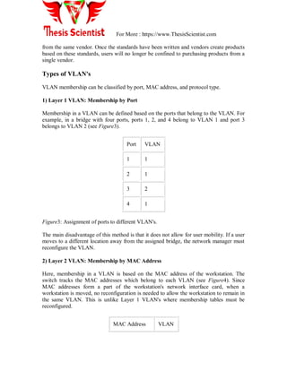
![For More : https://www.ThesisScientist.com
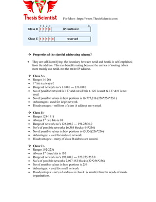
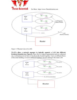
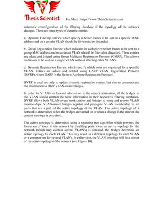
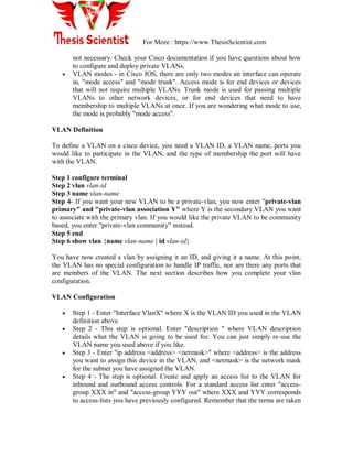
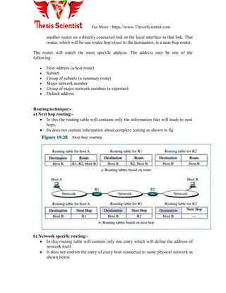
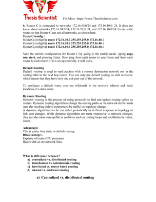
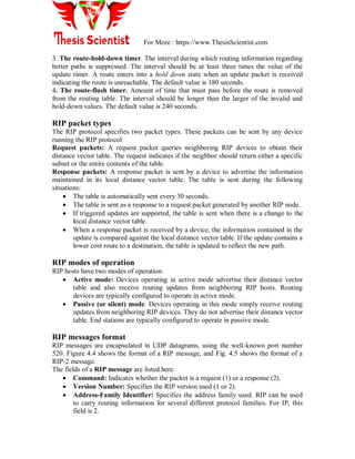
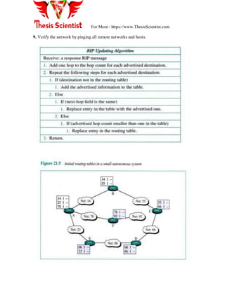
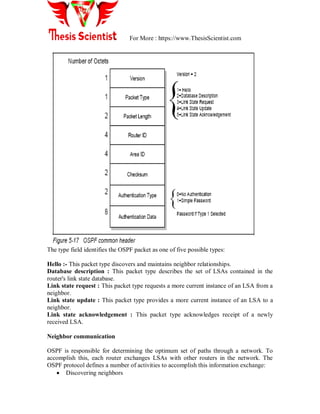
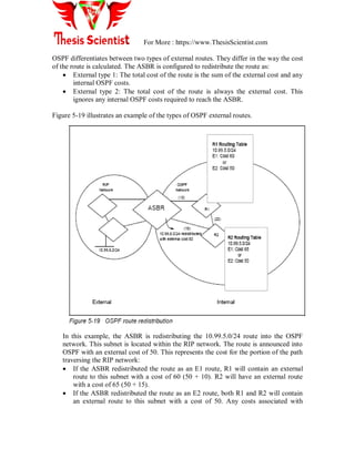
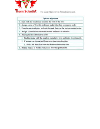
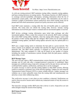
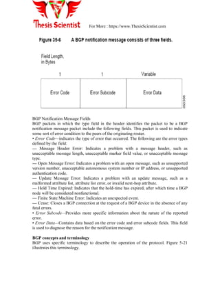
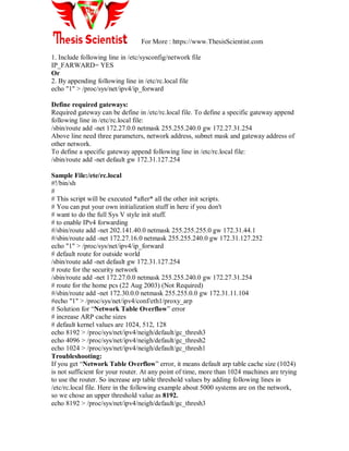
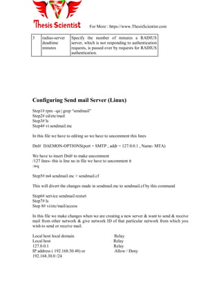
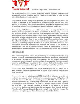
Figure9: Hybrid link containing both VLAN-aware and VLAN-unaware devices.
It must also be noted that the network can have a combination of all three types of links.
Frame Processing
A bridge on receiving data determines to which VLAN the data belongs either by implicit
or explicit tagging. In explicit tagging a tag header is added to the data. The bridge also
keeps track of VLAN members in a filtering database which it uses to determine where
the data is to be sent. Following is an explanation of the contents of the filtering database
and the format and purpose of the tag header [802.1Q].
1) Filtering Database
Membership information for a VLAN is stored in a filtering database. The filtering
database consists of the following types of entries:
i) Static Entries
Static information is added, modified, and deleted by management only. Entries are not
automatically removed after some time (ageing), but must be explicitly removed by
management. There are two types of static entries:
a) Static Filtering Entries: which specify for every port whether frames to be sent to a
specific MAC address or group address and on a specific VLAN should be forwarded or
discarded, or should follow the dynamic entry, and
b) Static Registration Entries: which specify whether frames to be sent to a specific
VLAN are to be tagged or untagged and which ports are registered for that VLAN.
ii) Dynamic Entries
Dynamic entries are learned by the bridge and cannot be created or updated by
management. The learning process observes the port from which a frame, with a given
source address and VLAN ID (VID), is received, and updates the filtering database. The
entry is updated only if all the following three conditions are satisfied:
a) this port allows learning,
b) the source address is a workstation address and not a group address, and
c) there is space available in the database.
Entries are removed from the database by the ageing out process where, after a certain
amount of time specified by management (10 sec --- 1000000 sec), entries allow](https://image.slidesharecdn.com/unit-2sna-170509130055/85/SYSTEM-NETWORK-ADMINISTRATIONS-GOALS-and-TIPS-21-320.jpg)
![For More : https://www.ThesisScientist.com
c) Dynamic routing
Static routing:-
Static routing is the process of an administrator manually adding routes in each router‘s
routing table. In static routing algorithms, routes change very slowly over time, often as a
result of human intervention (e.g., a human manually editing a router's forwarding table).
Static routing has the following benefits:
No overhead on the router CPU
No bandwidth usage between routers
Security (because the administrator only allows routing to certain networks)
Static routing has the following disadvantages:
The administrator must really understand the internet work and how each router is
connected to configure the routes correctly.
If one network is added to the internet work, the administrator must add a route to
it on all routers.
It‘s not feasible in large networks because it would be a full-time job.
The command used to add a static route to a routing table is
ip route [destination_network] [mask] [next_hop_address or exit interface]
[administrative_distance][permanent]
The following list describes each command in the string:
a) Ip route The command used to create the static route.
b) Destination network The network you are placing in the routing table.
c) Mask Indicates the subnet mask being used on the network.
d) Next hop address The address of the next hop router that will receive the
packet and forward it to the remote network. This is a router interface that is
on a directly connected network. You must be able to ping the router interface
before you add the route.
e) Exit interface Used in place of the next hop address if desired. Must be on a
point-to-point link, such as a WAN. This command does not work on a LAN;
for example, Ethernet.
f) Administrative distance By default, static routes have an administrative
distance of 1. You can change the default value by adding an administrative
weight at the end of the command.
g) Permanent If the interface is shut down or the router cannot communicate to
the next hop router, the route is automatically discarded from the routing
table. Choosing the permanent option keeps the entry in the routing table no
matter what happens.
Administrative Distances
When configuring routing protocols, you need to be aware of administrative distances
(ADs). These are used to rate the trustworthiness of routing information received on a](https://image.slidesharecdn.com/unit-2sna-170509130055/85/SYSTEM-NETWORK-ADMINISTRATIONS-GOALS-and-TIPS-32-320.jpg)


![For More : https://www.ThesisScientist.com
• If needed, use the aaa accounting command to enable accounting for RADIUS
connections. For more information about using the aaa accounting command, refer to the
"Configuring Accounting" chapter.
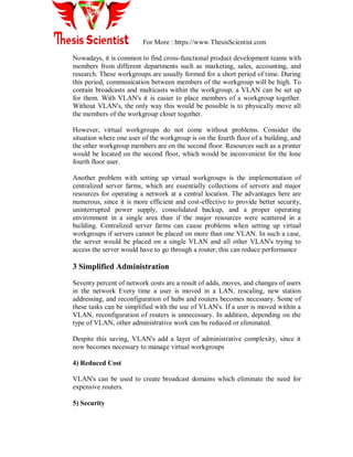
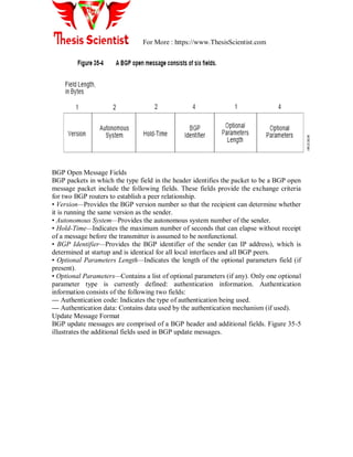
Configure Router to RADIUS Server Communication
The RADIUS host is normally a multiuser system running RADIUS server software from
Livingston, Merit, Microsoft, or another software provider. A RADIUS server and a
Cisco router use a shared secret text string to encrypt passwords and exchange responses.
To configure RADIUS to use the AAA security commands, you must specify the host
running the RADIUS server daemon and a secret text string that it shares with the router.
Use the radius-server commands to specify the RADIUS server host and a secret text
string.
To specify a RADIUS server host and shared secret text string, use the following
commands in global configuration mode:
Step Command Purpose
1 radius-server host
{hostname | ip-address}
[auth-port port-number]
[acct-port port-number]
Specify the IP address or host name
of the remote RADIUS server host
and assigns authentication and
accounting destination port numbers.
2 radius-server key string Specify the shared secret text string
used between the router and the
RADIUS server.
To customize communication between the router and the RADIUS server, use the
following optional radius-server global configuration commands:
Step Command Purpose
1 radius-server
retransmit
retries
Specify the number of times the router transmits
each RADIUS request to the server before
giving up (default is three).
2 radius-server
timeout
seconds
Specify the number of seconds a router waits for
a reply to a RADIUS request before
retransmitting the request.](https://image.slidesharecdn.com/unit-2sna-170509130055/85/SYSTEM-NETWORK-ADMINISTRATIONS-GOALS-and-TIPS-105-320.jpg)

![For More : https://www.ThesisScientist.com
TCP/IP Troubleshooting: ping, traceroute, ifconfig,
netstat, ipconfig
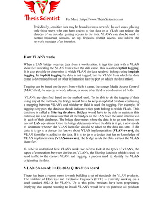
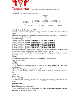
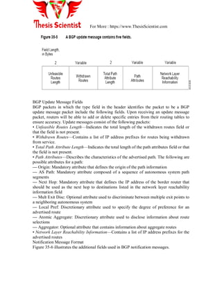
1 PING
Verifies IP-level connectivity to another TCP/IP computer by sending Internet Control
Message Protocol (ICMP) Echo Request messages. The receipt of corresponding Echo
Reply messages are displayed, along with round-trip times. Ping is the primary TCP/IP
command used to troubleshoot connectivity, reachability, and name resolution. Used
without parameters, ping displays help. It‘s Stands for ―Packet Internet Groper‖
ping [-t] [-a] [-n Count] [-l Size] [-f] [-i TTL] [-v TOS] [-r Count] [-s Count] [{-
j HostList | -k HostList}] [-w Timeout] [TargetName]
C:>ping 192.168.1.110
Pinging 192.168.1.110 with 32 bytes of data:
Reply from 192.168.1.110: bytes=32 time<1ms TTL=128
Reply from 192.168.1.110: bytes=32 time<1ms TTL=128
Reply from 192.168.1.110: bytes=32 time<1ms TTL=128
Reply from 192.168.1.110: bytes=32 time<1ms TTL=128
Ping statistics for 192.168.1.110:
Packets: Sent = 4, Received = 4, Lost = 0 (0% loss),
Approximate round trip times in milli-seconds:
Minimum = 0ms, Maximum = 0ms, Average = 0ms
2. TRACERT
Determines the path taken to a destination by sending Internet Control Message Protocol
(ICMP) Echo Request messages to the destination with incrementally increasing Time to
Live (TTL) field values. The path displayed is the list of near-side router interfaces of the
routers in the path between a source host and a destination. The near-side interface is the
interface of the router that is closest to the sending host in the path. Used without
parameters, tracert displays help.
tracert [-d] [-h MaximumHops] [-j HostList] [-w Timeout] [TargetName]](https://image.slidesharecdn.com/unit-2sna-170509130055/85/SYSTEM-NETWORK-ADMINISTRATIONS-GOALS-and-TIPS-115-320.jpg)
![For More : https://www.ThesisScientist.com
C:>tracert 192.168.1.110
Tracing route to 192.168.1.110 over a maximum of 30 hops
1 <1 ms <1 ms <1 ms 192.168.1.110
Trace complete.
3. IPCONFIG
Displays all current TCP/IP network configuration values and refreshes Dynamic Host
Configuration Protocol (DHCP) and Domain Name System (DNS) settings. Used without
parameters, ipconfig displays the IP address, subnet mask, and default gateway for all
adapters.
ipconfig [/all] [/renew [Adapter]] [/release [Adapter]] [/flushdns] [/displaydns]
[/registerdns] [/showclassid Adapter] [/setclassid Adapter [ClassID]]
C:>ipconfig
Windows IP Configuration
Ethernet adapter Local Area Connection:
Connection-specific DNS Suffix . :
IP Address. . . . . . . . . . . . : 192.168.1.113
Subnet Mask . . . . . . . . . . . : 255.255.255.0
Default Gateway . . . . . . . . . : 192.168.1.254
C:>ipconfig /all
Windows IP Configuration
Host Name . . . . . . . . . . . . : lab1com20
Primary Dns Suffix . . . . . . . :
Node Type . . . . . . . . . . . . : Unknown
IP Routing Enabled. . . . . . . . : No
WINS Proxy Enabled. . . . . . . . : No
Ethernet adapter Local Area Connection:
Connection-specific DNS Suffix . :
Description . . . . . . . . . . . : Realtek RTL8139 Family PCI
Fast Ethernet NIC
Physical Address. . . . . . . . . : 00-11-09-16-6B-73
Dhcp Enabled. . . . . . . . . . . : No
IP Address. . . . . . . . . . . . : 192.168.1.113
Subnet Mask . . . . . . . . . . . : 255.255.255.0
Default Gateway . . . . . . . . . : 192.168.1.254
DNS Servers . . . . . . . . . . . : 192.168.1.254](https://image.slidesharecdn.com/unit-2sna-170509130055/85/SYSTEM-NETWORK-ADMINISTRATIONS-GOALS-and-TIPS-116-320.jpg)
![For More : https://www.ThesisScientist.com
IPCONFIG /RELEASE or /RENEW - Release or renew an IP Address from a DHCP
Server
4. PATHPING
Provides information about network latency and network loss at intermediate hops
between a source and destination. Pathping sends multiple Echo Request messages to
each router between a source and destination over a period of time and then computes
results based on the packets returned from each router. Because pathping displays the
degree of packet loss at any given router or link, you can determine which routers or
subnets might be having network problems. Pathping performs the equivalent of the
tracert command by identifying which routers are on the path. It then sends pings
periodically to all of the routers over a specified time period and computes statistics
based on the number returned from each. Used without parameters, pathping displays
help.
pathping [-n] [-h MaximumHops] [-g HostList] [-p Period] [-q NumQueries [-w
Timeout] [-T] [-R] [TargetName]
C:>pathping 192.168.1.110
Tracing route to 192.168.1.110 over a maximum of 30 hops
0 lab1com20 [192.168.1.113]
1 192.168.1.110
Computing statistics for 25 seconds...
Source to Here This Node/Link
Hop RTT Lost/Sent = Pct Lost/Sent = Pct Address
0 lab1com20 [192.168.1.113]
0/ 100 = 0% |
1 0ms 0/ 100 = 0% 0/ 100 = 0% 192.168.1.110
Trace complete.
5. NET
You can use the net user command to create and modify user accounts on computers.
When you use this command without command-line switches, the user accounts for the
computer are listed. The user account information is stored in the user accounts database.
This command works only on servers.
C:>NET HELP](https://image.slidesharecdn.com/unit-2sna-170509130055/85/SYSTEM-NETWORK-ADMINISTRATIONS-GOALS-and-TIPS-117-320.jpg)
![For More : https://www.ThesisScientist.com
C:>NET USE
New connections will be remembered.
There are no entries in the list.
C:>NET USER
User accounts for LAB1COM20
---------------------------------------------------------------------------
Admin Administrator Guest
HelpAssistant Rajat SUPPORT_388945a0
user
The command completed successfully.
C:>NET VIEW
Server Name Remark
---------------------------------------------------------------------------
LAB1COM10
LAB1COM11
LAB1COM12
LAB1COM13
LAB1COM14
-------------
The command completed successfully.
6. NETSAT
Displays active TCP connections, ports on which the computer is listening, Ethernet
statistics, the IP routing table, IPv4 statistics (for the IP, ICMP, TCP, and UDP
protocols), and IPv6 statistics (for the IPv6, ICMPv6, TCP over IPv6, and UDP over IPv6
protocols). Used without parameters, netstat displays active TCP connections.
netstat [-a] [-e] [-n] [-o] [-p Protocol] [-r] [-s] [Interval]
C:>NETSTAT -a
Active Connections
Proto Local Address Foreign Address State
TCP lab1com20:epmap lab1com20:0 LISTENING
TCP lab1com20:microsoft-ds lab1com20:0 LISTENING
TCP lab1com20:1025 lab1com20:0 LISTENING
TCP lab1com20:5000 lab1com20:0 LISTENING
TCP lab1com20:netbios-ssn lab1com20:0 LISTENING
UDP lab1com20:epmap *:*
UDP lab1com20:microsoft-ds *:*
UDP lab1com20:isakmp *:*](https://image.slidesharecdn.com/unit-2sna-170509130055/85/SYSTEM-NETWORK-ADMINISTRATIONS-GOALS-and-TIPS-119-320.jpg)


Network administration encompasses the management of network infrastructure devices, ensuring users receive quality services. It involves three major groups: network provisioning, operations, and maintenance, and requires understanding IP addressing, subnetting, and classful addressing schemes. VLANs offer logical segmentation of LANs, allowing devices to be grouped together without physical proximity.


![[Deck] What's New in Spark-Iceberg Integration via DSV2.pptx](https://cdn.slidesharecdn.com/ss_thumbnails/deckwhatsnewinspark-icebergintegrationviadsv2-260210005337-25955b12-thumbnail.jpg?width=640&height=640&fit=bounds)


