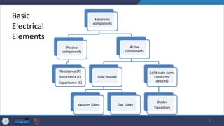
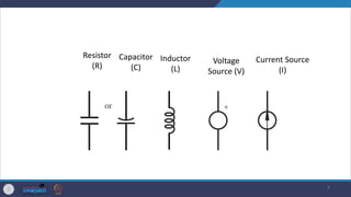
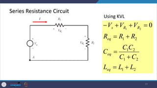
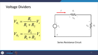
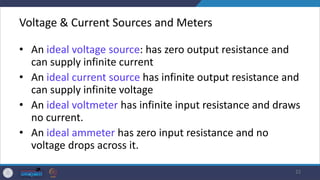
- The document provides an overview of basic concepts in electric circuits and components important for mechatronics, including definitions of voltage, current, resistance, capacitance, inductance, and different circuit types.
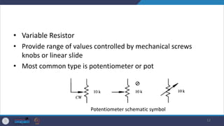
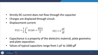
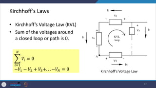
- It describes common passive components like resistors, capacitors, inductors and discusses their properties and applications. Kirchhoff's laws for circuit analysis are also introduced.
- The document concludes by discussing equivalent circuit models like Thevenin and Norton equivalents that are used to simplify complex circuit analyses.