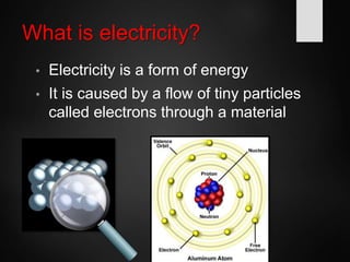
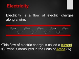
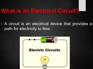
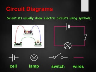
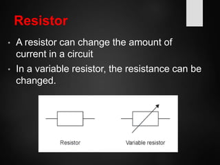
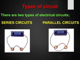
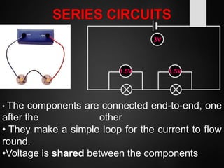
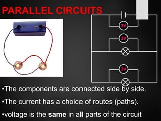
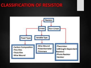
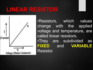
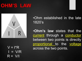
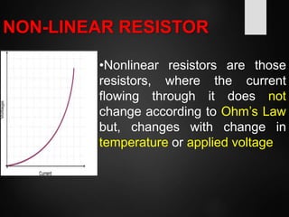
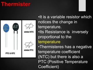
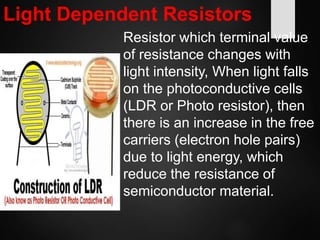
BASICS OF ELECTRICLE
MODULE
BY KUNAL PATIL
ADAM 2016-2017
People
Benjamin Franklin
Thomas Edison
• Why are they important?
• Benjamin Franklin
• Proved that lightning was electricity by
flying a kite in a lightning storm
• Helped people understand the principles
of electricity
• Thomas Edison
–Invented the electrical light bulb
What is electricity?
• Electricity is a form of energy
• It is caused by a flow of tiny particles
called electrons through a material
Electricity
Electricity is a flow of electric charges
along a wire.
•This flow of electric charge is called a current
•Current is measured in the units of Amps (A)
What is an Electrical Circuit?
• A circuit is an electrical device that provides a
path for electricity to flow.
Circuit Diagrams
cell switchlamp wires
Resistor
• A resistor can change the amount of
current in a circuit
• In a variable resistor, the resistance can be
changed.
Types of circuit
There are two types of electrical circuits;
SERIES CIRCUITS PARALLEL CIRCUITS
• The components are connected end-to-end, one
after the other
• They make a simple loop for the current to flow
round.
•Voltage is shared between the components
SERIES CIRCUITS
1.5V 1.5V
3V
PARALLEL CIRCUITS
•The components are connected side by side.
•The current has a choice of routes (paths).
•voltage is the same in all parts of the circuit
3V
3V
3V
RESISTORS
symbolHow its looks
DEFINITION OF 1 OHM
The resistance of a conductor is said to be 1 Ohm, if
current of 1 ampere flows through it when a
potential difference of 1volt is applied its ends.
…Continued
UNIT OF CONVERSION
Prefix Symbol Multiplier Power of Ten
Terra T 1,000,000,000,000 1012
Giga G 1,000,000,000 109
Mega M 1,000,000 106
kilo k 1,000 103
none none 1 100
centi c 1/100 10-2
milli m 1/1,000 10-3
micro µ 1/1,000,000 10-6
nano n 1/1,000,000,000 10-9
pico p 1/1,000,000,000,000 10-12
CLASSIFICATION OF RESISTOR
LINEAR RESISTOR
•Resistors, which values
change with the applied
voltage and temperature, are
called linear resistors.
•They are subdivided as
FIXED and VARIABLE
Resistor.
OHM’S LAW
•Ohm established in the late
1820’s
•Ohm's law states that the
current through a conductor
between two points is directly
proportional to the voltage
across the two points.V = I*R
I = V/R
R = V/I
NON-LINEAR RESISTOR
•Nonlinear resistors are those
resistors, where the current
flowing through it does not
change according to Ohm’s Law
but, changes with change in
temperature or applied voltage
Thermister
•It is a variable resistor which
notices the change in
temperature.
•Its Resistance is inversely
proportional to the
temperature
•Thermisteres has a negative
temperature coefficient
(NTC) but there is also a
PTC (Positive Temperature
Coefficient)
Voltage Dependent Resistors
•The resistance of a VDR is
variable and depends on the
voltage applied
•Their resistance decreases
when the voltage increases.
Light Dependent Resistors
Resistor which terminal value
of resistance changes with
light intensity, When light falls
on the photoconductive cells
(LDR or Photo resistor), then
there is an increase in the free
carriers (electron hole pairs)
due to light energy, which
reduce the resistance of
semiconductor material.
BASICS OF ELECTRICAL MODULE

BASICS OF ELECTRICAL MODULE

  • 1.
    BASICS OF ELECTRICLE MODULE BYKUNAL PATIL ADAM 2016-2017
  • 2.
  • 3.
    • Benjamin Franklin •Proved that lightning was electricity by flying a kite in a lightning storm • Helped people understand the principles of electricity • Thomas Edison –Invented the electrical light bulb
  • 4.
    What is electricity? •Electricity is a form of energy • It is caused by a flow of tiny particles called electrons through a material
  • 5.
    Electricity Electricity is aflow of electric charges along a wire. •This flow of electric charge is called a current •Current is measured in the units of Amps (A)
  • 6.
    What is anElectrical Circuit? • A circuit is an electrical device that provides a path for electricity to flow.
  • 7.
  • 8.
    Resistor • A resistorcan change the amount of current in a circuit • In a variable resistor, the resistance can be changed.
  • 10.
    Types of circuit Thereare two types of electrical circuits; SERIES CIRCUITS PARALLEL CIRCUITS
  • 11.
    • The componentsare connected end-to-end, one after the other • They make a simple loop for the current to flow round. •Voltage is shared between the components SERIES CIRCUITS 1.5V 1.5V 3V
  • 12.
    PARALLEL CIRCUITS •The componentsare connected side by side. •The current has a choice of routes (paths). •voltage is the same in all parts of the circuit 3V 3V 3V
  • 13.
  • 14.
    DEFINITION OF 1OHM The resistance of a conductor is said to be 1 Ohm, if current of 1 ampere flows through it when a potential difference of 1volt is applied its ends.
  • 15.
  • 16.
    UNIT OF CONVERSION PrefixSymbol Multiplier Power of Ten Terra T 1,000,000,000,000 1012 Giga G 1,000,000,000 109 Mega M 1,000,000 106 kilo k 1,000 103 none none 1 100 centi c 1/100 10-2 milli m 1/1,000 10-3 micro µ 1/1,000,000 10-6 nano n 1/1,000,000,000 10-9 pico p 1/1,000,000,000,000 10-12
  • 17.
  • 18.
    LINEAR RESISTOR •Resistors, whichvalues change with the applied voltage and temperature, are called linear resistors. •They are subdivided as FIXED and VARIABLE Resistor.
  • 19.
    OHM’S LAW •Ohm establishedin the late 1820’s •Ohm's law states that the current through a conductor between two points is directly proportional to the voltage across the two points.V = I*R I = V/R R = V/I
  • 20.
    NON-LINEAR RESISTOR •Nonlinear resistorsare those resistors, where the current flowing through it does not change according to Ohm’s Law but, changes with change in temperature or applied voltage
  • 21.
    Thermister •It is avariable resistor which notices the change in temperature. •Its Resistance is inversely proportional to the temperature •Thermisteres has a negative temperature coefficient (NTC) but there is also a PTC (Positive Temperature Coefficient)
  • 22.
    Voltage Dependent Resistors •Theresistance of a VDR is variable and depends on the voltage applied •Their resistance decreases when the voltage increases.
  • 23.
    Light Dependent Resistors Resistorwhich terminal value of resistance changes with light intensity, When light falls on the photoconductive cells (LDR or Photo resistor), then there is an increase in the free carriers (electron hole pairs) due to light energy, which reduce the resistance of semiconductor material.