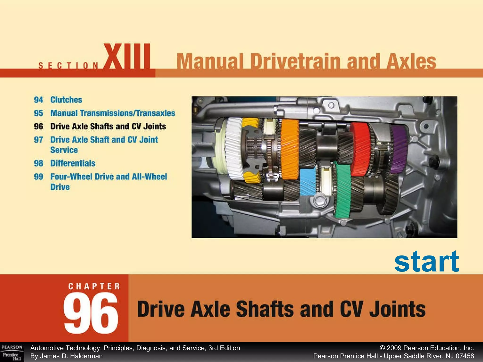
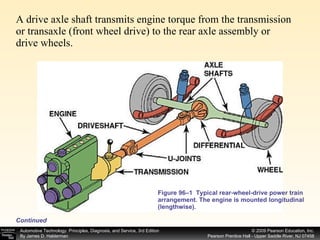
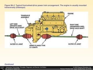
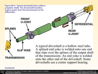
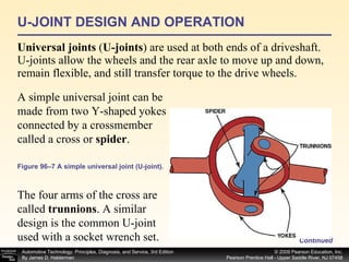
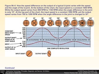
start
Prepare for ASE Suspension and Steering (A4) certification test content area “C” (Related Suspension and Steering Service). Name driveshaft and U-joint parts, and describe their function and operation. Describe how CV joints work. OBJECTIVES: After studying Chapter 96, the reader should be able to: Continued
Explain how the working angles of the U-joints are determined. List the various types of CV joints and their applications. OBJECTIVES: After studying Chapter 96, the reader should be able to:
cardan joints • center support bearing • CV joint boot • CV joints double-cardan joints • drive axle shaft • driveshaft fixed joint half shaft plunge joint • propeller shaft Rzeppa joint • spider trunnions • universal joints KEY TERMS:
A drive axle shaft transmits engine torque from the transmission or transaxle (if front wheel drive) to the rear axle assembly or drive wheels. Driveshaft is the term used by the Society of Automotive Engineers (SAE) to describe the shaft between the transmission and the rear axle assembly on a rear-wheel-drive vehicle. The SAE term will be used throughout this textbook.
A drive axle shaft transmits engine torque from the transmission or transaxle (front wheel drive) to the rear axle assembly or drive wheels.  Figure 96–1  Typical rear-wheel-drive power train arrangement. The engine is mounted longitudinal (lengthwise).  Continued
Figure 96–2  Typical front-wheel-drive power train arrangement. The engine is usually mounted transversely (sideways).  Continued
Figure 96–3  Typical driveshaft (also called a  propeller shaft ). The drivershaft transfers engine power from the transmission to the differential. A typical driveshaft is a hollow steel tube. A splined end yoke is welded onto one end that slips over the splines of the output shaft of the transmission. An end yoke is welded onto the other end of the driveshaft. Some driveshafts use a center support bearing. Continued
DRIVESHAFT DESIGN Most driveshafts are constructed of hollow steel tubing.  The forces are transmitted through the surface of the driveshaft tubing.  The surface is in tension, and cracks can develop on the outside surface of the driveshaft due to metal fatigue. Driveshaft tubing can bend and, if dented, can collapse.  Continued Figure 96–4  This driveshaft failed because it had a slight dent caused by a rock. When engine torque was applied, the driveshaft collapsed, twisted, and then broke.
Most rear-wheel-drive cars and light trucks use a one- or two-piece driveshaft. A steel tube driveshaft has a  maximum   length of about  65 in. (165 cm) . Beyond this length, a  center support bearing , called a steady bearing or hanger bearing, must be used. Some vehicle manufacturers use aluminum driveshafts; these can be as long as 90 in. (230 cm) with no problem. Many extended-cab pickup trucks and certain vans use aluminum driveshafts to eliminate the need (and expense) of a center support bearing. Composite-material driveshafts are also used in some vehicles. These carbon-fiber-plastic driveshafts are very strong yet lightweight, and canbe made in extended lengths without the need for a center support bearing. See Figure 96–5. Continued
Figure 96–5 A center support bearing is used on many vehicles with long driveshafts.
Figure 96–6  Some driveshafts use rubber between an inner and outer housing to absorb vibrations and shocks to the driveline. To dampen driveshaft noise, it is common to line the inside of the hollow driveshaft with cardboard. This helps eliminate the tinny sound whenever shifting between drive and reverse in a vehicle equipped with an automatic transmission.  Continued
DRIVESHAFT BALANCE All driveshafts are balanced. Generally, any driveshaft whose rotational speed is greater than 1000 RPM must be balanced. Driveshaft balance should be within 0.5% of the driveshaft weight. (This is one reason why aluminum or composite driveshafts can be longer because of their light weight.) Driveshafts are often not available by make, model, and year of the vehicle. There are too many variations at the factory, such as transmission type, differential, or U-joint type. To get a replacement driveshaft, it is usually necessary to know the series of U-joints (type or style of U-joint) and the center-to-center distance between the U-joints. Continued
U-JOINT DESIGN AND OPERATION Universal joints  ( U-joints ) are used at both ends of a driveshaft. U-joints allow the wheels and the rear axle to move up and down, remain flexible, and still transfer torque to the drive wheels. A simple universal joint can be made from two Y-shaped yokes connected by a crossmember called a cross or  spider . The four arms of the cross are called  trunnions . A similar design is the common U-joint used with a socket wrench set. Continued Figure 96–7 A simple universal joint (U-joint).
Most U-joints are called cross-yoke joints or  Cardan joints , named for a sixteenth-century Italian mathematician who worked with objects that moved freely in any direction. Torque from the engine is transferred through the U-joint. The engine drives the U-joint at a constant speed, but the output speed of the U-joint changes because of the angle of the joint. The speed changes twice per revolution. See Figure 96–8. Continued The greater the angle, the greater the change in speed (velocity ) .
Figure 96–8  How the speed difference on the output of a typical U-joint varies with the speed and the angle of the U-joint. At the bottom of the chart, the input speed is a constant 1000 RPM, While the output speed varies from 900 RPM to 1100 RPM when the angle difference in the joint is only 10°. At the top part of the chart, the input speed is a constant 1000 RPM, yet the output speed varies from 700 to 1200 RPM when the angle difference in the joint is changed to 30°.   Continued
If one U-joint were used in a driveline, change in speed of the driven side (output end) would generate vibrations in the driveline. To help reduce vibration, another U-joint is used at the other end of the driveshaft. If the angles of both joints are nearly equal, the acceleration and deceleration of one joint is offset by the alternate deceleration and acceleration of the second joint.  Figure 96–9  The joint angle is the difference between the angles of the joint.  (Courtesy of Dana Corporation) It is very important that both U-joints operate at about the same angle to prevent excessive driveline vibration .
Acceptable Working Angles   Universal joints used in a typical driveshaft should have a  working angle  of 1/2 to 3 degrees. The working angle is the angle between the driving and driven end of the joint. If the driveshaft is perfectly straight (0-degree working angle), then the needle bearings inside the bearing cap are not revolving because there is no force (no difference in angles) to cause the rotation of the needle bearings. If the needle bearings do not rotate, they can exert a constant pressure in one place and damage the bearing journal.  See Figure 96–10.  Continued
Figure 96–10  The angle of this rear U-joint is noticeable. If a two-piece driveshaft is used, one U-joint (usually the front) runs at a small working angle of about 1/2 degree, just enough to keep the needle bearings rotating. The other two U-joints (from the center support bearing and rear U-joint at the differential) operate at typical working angles of a single-piece driveshaft. Continued
If the U-joint working angles differ by more than 1/2 degree, a vibration is usually produced that is  torque sensitive.  As the vehicle is first accelerated from a stop, engine torque can create unequal driveshaft angles by causing the differential to rotate on its suspension support arms. This vibration is most noticeable when the vehicle is heavily loaded and being accelerated at lower speeds. The vibration usually diminishes at higher speeds due to decrease in the torque being transmitted. If the driveshaft angles are excessive (over 3 degrees), a vibration is usually produced that increases as the speed of the vehicle (and driveshaft) increases. Continued
CONSTANT VELOCITY JOINTS Constant velocity joints, commonly called  CV joints , are designed to rotate without changing speed. Regular U-joints are usually designed to work up to 12 degrees of angularity.  Continued Figure 96–11  A double-Cardan U-joint.  If two Cardan-style U-joints are joined together, the angle at which this  double - Cardan joint can function is about 18 to 20 degrees.
Most universal joints are available in sizes to best match the torque that they transmit. The larger the U-joint, the higher the amount of torque. Most U-joints are sized and rated by series numbers.  What Is a 1350-Series U-Joint? See the chart on Page 1242 of your textbook.
Double-Cardan U-joints were first used on large rear-wheel-drive vehicles to help reduce drive-line-induced vibrations, especially when the rear of the vehicle was fully loaded and driveshaft angles were at their greatest. As long as a U-joint (either single or double Cardan) operates in a straight line, the driven shaft will rotate at the same constant speed (velocity) as the driving shaft. As the angle increases, the driven shaft speed or velocity varies during each revolution. This produces pulsations and a noticeable vibration or surge. The higher the shaft speed and the greater the angle of the joint, the greater the pulsations. Continued
NOTE:   Many four-wheel-drive light trucks use standard Cardan-style  U-joints in the front drive axles. If the front wheels are turned sharply  and then accelerated, the entire truck often shakes due to the pulsations created by the speed variations through the U-joints. This vibration is normal and cannot be corrected. It is characteristic of this type of design and is usually not noticeable in normal driving.
The first constant velocity joint was designed by AlfredH. Rzeppa (pronounced shep’pa) in the mid-1920s. The  Rzeppa joint  transfers torque through six round balls that are held in position midway between the two shafts. This design causes the angle between the shafts to be equally split regardless of the angle.  Because the angle is always split equally, torque is transferred equally without the change in speed (velocity) that occurs in Cardan-style U-joints. This style of joint results in a constant velocity between driving and driven shafts. It can also function at angles greater than simple U-joints can, up to 40 degrees. See Figure 96–12.  Continued
Figure 96–12  A constant velocity (CV) joint can operate at high angles without a change in velocity (speed) because the joint design results in equal angles between input and output.  NOTE:   CV joints are also called LOBRÖ joints, the brand name of an original equipment manufacturer. Continued
Outer CV Joints   The Rzeppa-type CV joint is most commonly used as an outer joint on most front-wheel-drive vehicles. See Figure 96–13.  Continued The outer joint must do the following: Allow up to 40 degrees or more of movement to allow the front wheels to turn Allow the front wheels to move up and down through normal suspension travel in order to provide a smooth ride over rough surfaces Be able to transmit engine torque to drive the front wheels See Figure 96–13.
Figure 96–13  A Rzeppa fixed joint. This type of CV joint is commonly used at the wheel side of the drive axle shaft. This joint can operate at high angles to compensate for suspension travel and steering angle changes.  (Courtesy of Dana Corporation)   Continued
Outer CV joints are called  fixed joints . The outer joints are also attached to the front wheels. They are more likely to suffer from road hazards that often can cut through the protective outer flexible boot. See Figure 96–14. Once this boot has been split open, the special high-quality grease is thrown out and contaminants such as dirt and water can enter. Some joints cannot be replaced individually if worn. See Figure 96–15. Continued
Figure 96–14  The protective CV joint boot has been torn away on this vehicle and all of the grease has been thrown outward onto the brake and suspension parts. The driver of this vehicle noticed a “clicking” noise, especially when turning. Figure 96–15  A tripod fixed joint. This type of joint is found on some Japanese vehicles. If the joint wears out, it is to be replaced with an entire drive axle shaft assembly.   Continued
Figure 96–16  The fixed outer joint is required to move in all directions because the wheels must turn for steering as well as move up and down during suspension movement. The inner joint has to be able to not only move up and down but also plunge in and out as the suspension moves up and down.  (Courtesy of Dana Corporation) Inner CV Joints   Attach the output of the transaxle to the drive axle shaft. Inner CV joints are inboard, or toward the center of the vehicle. Continued
Inner CV joints have to be able to perform two very important movements:  NOTE:   Research has shown that in as few as eight hours of driving time, a CV joint can be destroyed by dirt, moisture, and a lack of lubrication if the boot is torn. The tech should warn the owner as to the cost involved in replacing the CV joint itself whenever a torn CV boot is found. Allow the drive axle shaft to move up and down as the wheels travel over bumps. Allow the drive axle shaft to change length as required during vehicle suspension travel movements (lengthening and shortening as the vehicle moves up and down; same as the slip yoke on a conventional RWD driveshaft). CV joints are also called  plunge joints . Continued
Drive Axle Shafts   Unequal-length  drive axle shafts  (also called  half shafts ) result in unequal drive axle shaft angles to the front drive wheels. This unequal angle often results in a pull on the steering wheel during acceleration. This pulling to one side during acceleration due to unequal engine torque being applied to the front drive wheels is called torque steer. To help reduce the effect of torque steer, some vehicles are manufactured with an intermediate shaft that results in equal drive axle shaft angles. Both designs use fixed outer CV joints with plunge-type inner joints. See Figure 96–17. Continued
Figure 96–17  Unequal-length driveshafts result in unequal drive axle shaft ngles to the front drive wheels. This unequal angle side-to-side often results in a steering of the vehicle during acceleration called torque steer. By using an intermediate shaft, both drive axles are the same angle and the torque steer effect is reduced.  (Courtesy of Dana Corporation) See the entire illustration on Page 1244 of your textbook.
Some drive axle shafts are equipped with what looks like a balance weight. It is actually a dampener weight used to dampen out certain drive line vibrations. The weight is not used on all vehicles and may or may not appear on the same vehicle depending on engine, transmission, and other options. The service technician should always try to replace a defective or worn drive axle shaft with the exact replacement.  Figure 96–18 A typical drive axle shaft with dampener weight. What Is That Weight for on the Drive Axle Shaft?   When replacing an entire drive axle shaft, the tech should always follow the manufacturer instructions regarding transferring the weight to the new shaft.
Figure 96–19  A tripod joint is also called a tripot, tripode, or tulip design.  (Courtesy of Dana Corp) Inner CV joints designed to move axially, or  plunge: Continued Tripod. See Figure 96–19. Cross groove. See Figure 96–20. Double offset. See Figure 96–21.
Figure 96–20  A cross-groove plunge joint is used on many German front-wheel-drive vehicles and as both inner and outer joints on the rear of vehicles that use an independent-type rear suspension.  (Courtesy of Dana Corporation) Continued
Figure 96–21  Double-offset ball-type plunge joint.  (Courtesy of Dana Corporation) Continued
CV Joint Boot Materials   The pliable boot surrounding the CV joint, or  CV joint boot , must be able to remain flexible under all weather conditions and still be strong enough to avoid being punctured by road debris.  Continued NOTE:   Some aftermarket companies offer a split-style replacement CV joint boot. Being split means that the boot can be replaced without having to remove the drive axle shaft. Vehicle manufacturers usually do  not  recommend this type of replacement boot because the joint cannot be disassembled and properly cleaned with the drive axle still in the vehicle. The split boots must also be kept perfectly clean (a hard job to do with all the grease in the joint) in order to properly seal the seam on the split boot.
Continued Four basic types of boot materials used over CV joints: 1. Natural rubber  (black) uses a bridge-type stainless steel clamp 2. Silicone rubber  (gray) is a high-temperature-resistant material that is usually only used in places that need heat protection, such as the inner CV joint of a front-wheel-drive vehicle. 3. Hard thermoplastic  (black) A hard plastic material requiring heavy-duty clamps and much torque (about 100 lb-ft!). 4. Urethane  (usually blue) is a type of boot material usually found in an aftermarket part. For examples of various types of CV joint boots depending on the manufacturer of the CV joints and shafts.   See Figure 96–22.
Figure 96–22  Getting the correct book kit or parts from the parts store is more difficult on many Chrysler front-wheel-drive vehicles because Chrysler has used four different manufacturers for its axle shaft assemblies  (Courtesy of Dana Corporation) It is important that boot seals be inspected regularly and replaced if damaged. Seal retainers are used to provide a leakproof connection between the boot seal and the housing or axle shaft. Continued
CV Joint Grease   CV joints require special greases. Most CV joint grease is molybdenum-disulfide-type grease, commonly referred to as  moly  grease. The exact composition of grease can vary depending on the CV joint manufacturer.  Continued The grease supplied with a replacement CV joint or boot kit should be the only grease used. The exact mix of chemicals, viscosity, wear, and corrosion-resistant properties varies from one CV joint application to another.  Some techs mistakenly think the  color  of the grease determines in where it is used. The color—such as  black ,  blue ,  red , or  tan —is used to identify the grease during manufacturing and packaging as well as to give the grease a consistent, even color (due to blending of various ingredients in the grease).
The exact grease to use depends on many factors, including: The type (style) of CV joint. For example, outer (fixed) and inner (plunging) joints have different lubricating needs. The location of the joint on the vehicle. For example, inner CV joints are usually exposed to the greatest amount of heat. The type of boot. The grease has to be compatible with the boot material.
SUMMARY The driveshaft of a rear-wheel-drive vehicle transmits engine torque from the transmission to the differential. Driveshaft length is usually limited to about 65 inches due to balancing considerations unless a two-piece or a composite material shaft is used. Universal joints (U-joints) allow the driveshaft to transmit engine torque while the suspension and the rear axle assembly are moving up and down during normal driving conditions. Acceptable working angles for a Cardan-type U-joint fall within 1/2 to 3 degrees. Some angle is necessary to cause the roller bearings to rotate; a working angle of greater than 3 degrees can lead to driveline vibrations. Continued
SUMMARY Constant velocity (CV) joints are used on all front-wheel-drive vehicles and many four-wheel-drive vehicles to provide a smooth transmission of torque to the drive wheels regardless of angularity of the wheel or joint. Outer or fixed CV joints commonly use a Rzeppa design, while inner CV joints are the plunging or tripod type. ( cont. )
end

Chap96

  • 1.
  • 2.
    Prepare for ASESuspension and Steering (A4) certification test content area “C” (Related Suspension and Steering Service). Name driveshaft and U-joint parts, and describe their function and operation. Describe how CV joints work. OBJECTIVES: After studying Chapter 96, the reader should be able to: Continued
  • 3.
    Explain how theworking angles of the U-joints are determined. List the various types of CV joints and their applications. OBJECTIVES: After studying Chapter 96, the reader should be able to:
  • 4.
    cardan joints •center support bearing • CV joint boot • CV joints double-cardan joints • drive axle shaft • driveshaft fixed joint half shaft plunge joint • propeller shaft Rzeppa joint • spider trunnions • universal joints KEY TERMS:
  • 5.
    A drive axleshaft transmits engine torque from the transmission or transaxle (if front wheel drive) to the rear axle assembly or drive wheels. Driveshaft is the term used by the Society of Automotive Engineers (SAE) to describe the shaft between the transmission and the rear axle assembly on a rear-wheel-drive vehicle. The SAE term will be used throughout this textbook.
  • 6.
    A drive axleshaft transmits engine torque from the transmission or transaxle (front wheel drive) to the rear axle assembly or drive wheels. Figure 96–1 Typical rear-wheel-drive power train arrangement. The engine is mounted longitudinal (lengthwise). Continued
  • 7.
    Figure 96–2 Typical front-wheel-drive power train arrangement. The engine is usually mounted transversely (sideways). Continued
  • 8.
    Figure 96–3 Typical driveshaft (also called a propeller shaft ). The drivershaft transfers engine power from the transmission to the differential. A typical driveshaft is a hollow steel tube. A splined end yoke is welded onto one end that slips over the splines of the output shaft of the transmission. An end yoke is welded onto the other end of the driveshaft. Some driveshafts use a center support bearing. Continued
  • 9.
    DRIVESHAFT DESIGN Mostdriveshafts are constructed of hollow steel tubing. The forces are transmitted through the surface of the driveshaft tubing. The surface is in tension, and cracks can develop on the outside surface of the driveshaft due to metal fatigue. Driveshaft tubing can bend and, if dented, can collapse. Continued Figure 96–4 This driveshaft failed because it had a slight dent caused by a rock. When engine torque was applied, the driveshaft collapsed, twisted, and then broke.
  • 10.
    Most rear-wheel-drive carsand light trucks use a one- or two-piece driveshaft. A steel tube driveshaft has a maximum length of about 65 in. (165 cm) . Beyond this length, a center support bearing , called a steady bearing or hanger bearing, must be used. Some vehicle manufacturers use aluminum driveshafts; these can be as long as 90 in. (230 cm) with no problem. Many extended-cab pickup trucks and certain vans use aluminum driveshafts to eliminate the need (and expense) of a center support bearing. Composite-material driveshafts are also used in some vehicles. These carbon-fiber-plastic driveshafts are very strong yet lightweight, and canbe made in extended lengths without the need for a center support bearing. See Figure 96–5. Continued
  • 11.
    Figure 96–5 Acenter support bearing is used on many vehicles with long driveshafts.
  • 12.
    Figure 96–6 Some driveshafts use rubber between an inner and outer housing to absorb vibrations and shocks to the driveline. To dampen driveshaft noise, it is common to line the inside of the hollow driveshaft with cardboard. This helps eliminate the tinny sound whenever shifting between drive and reverse in a vehicle equipped with an automatic transmission. Continued
  • 13.
    DRIVESHAFT BALANCE Alldriveshafts are balanced. Generally, any driveshaft whose rotational speed is greater than 1000 RPM must be balanced. Driveshaft balance should be within 0.5% of the driveshaft weight. (This is one reason why aluminum or composite driveshafts can be longer because of their light weight.) Driveshafts are often not available by make, model, and year of the vehicle. There are too many variations at the factory, such as transmission type, differential, or U-joint type. To get a replacement driveshaft, it is usually necessary to know the series of U-joints (type or style of U-joint) and the center-to-center distance between the U-joints. Continued
  • 14.
    U-JOINT DESIGN ANDOPERATION Universal joints ( U-joints ) are used at both ends of a driveshaft. U-joints allow the wheels and the rear axle to move up and down, remain flexible, and still transfer torque to the drive wheels. A simple universal joint can be made from two Y-shaped yokes connected by a crossmember called a cross or spider . The four arms of the cross are called trunnions . A similar design is the common U-joint used with a socket wrench set. Continued Figure 96–7 A simple universal joint (U-joint).
  • 15.
    Most U-joints arecalled cross-yoke joints or Cardan joints , named for a sixteenth-century Italian mathematician who worked with objects that moved freely in any direction. Torque from the engine is transferred through the U-joint. The engine drives the U-joint at a constant speed, but the output speed of the U-joint changes because of the angle of the joint. The speed changes twice per revolution. See Figure 96–8. Continued The greater the angle, the greater the change in speed (velocity ) .
  • 16.
    Figure 96–8 How the speed difference on the output of a typical U-joint varies with the speed and the angle of the U-joint. At the bottom of the chart, the input speed is a constant 1000 RPM, While the output speed varies from 900 RPM to 1100 RPM when the angle difference in the joint is only 10°. At the top part of the chart, the input speed is a constant 1000 RPM, yet the output speed varies from 700 to 1200 RPM when the angle difference in the joint is changed to 30°. Continued
  • 17.
    If one U-jointwere used in a driveline, change in speed of the driven side (output end) would generate vibrations in the driveline. To help reduce vibration, another U-joint is used at the other end of the driveshaft. If the angles of both joints are nearly equal, the acceleration and deceleration of one joint is offset by the alternate deceleration and acceleration of the second joint. Figure 96–9 The joint angle is the difference between the angles of the joint. (Courtesy of Dana Corporation) It is very important that both U-joints operate at about the same angle to prevent excessive driveline vibration .
  • 18.
    Acceptable Working Angles Universal joints used in a typical driveshaft should have a working angle of 1/2 to 3 degrees. The working angle is the angle between the driving and driven end of the joint. If the driveshaft is perfectly straight (0-degree working angle), then the needle bearings inside the bearing cap are not revolving because there is no force (no difference in angles) to cause the rotation of the needle bearings. If the needle bearings do not rotate, they can exert a constant pressure in one place and damage the bearing journal. See Figure 96–10. Continued
  • 19.
    Figure 96–10 The angle of this rear U-joint is noticeable. If a two-piece driveshaft is used, one U-joint (usually the front) runs at a small working angle of about 1/2 degree, just enough to keep the needle bearings rotating. The other two U-joints (from the center support bearing and rear U-joint at the differential) operate at typical working angles of a single-piece driveshaft. Continued
  • 20.
    If the U-jointworking angles differ by more than 1/2 degree, a vibration is usually produced that is torque sensitive. As the vehicle is first accelerated from a stop, engine torque can create unequal driveshaft angles by causing the differential to rotate on its suspension support arms. This vibration is most noticeable when the vehicle is heavily loaded and being accelerated at lower speeds. The vibration usually diminishes at higher speeds due to decrease in the torque being transmitted. If the driveshaft angles are excessive (over 3 degrees), a vibration is usually produced that increases as the speed of the vehicle (and driveshaft) increases. Continued
  • 21.
    CONSTANT VELOCITY JOINTSConstant velocity joints, commonly called CV joints , are designed to rotate without changing speed. Regular U-joints are usually designed to work up to 12 degrees of angularity. Continued Figure 96–11 A double-Cardan U-joint. If two Cardan-style U-joints are joined together, the angle at which this double - Cardan joint can function is about 18 to 20 degrees.
  • 22.
    Most universal jointsare available in sizes to best match the torque that they transmit. The larger the U-joint, the higher the amount of torque. Most U-joints are sized and rated by series numbers. What Is a 1350-Series U-Joint? See the chart on Page 1242 of your textbook.
  • 23.
    Double-Cardan U-joints werefirst used on large rear-wheel-drive vehicles to help reduce drive-line-induced vibrations, especially when the rear of the vehicle was fully loaded and driveshaft angles were at their greatest. As long as a U-joint (either single or double Cardan) operates in a straight line, the driven shaft will rotate at the same constant speed (velocity) as the driving shaft. As the angle increases, the driven shaft speed or velocity varies during each revolution. This produces pulsations and a noticeable vibration or surge. The higher the shaft speed and the greater the angle of the joint, the greater the pulsations. Continued
  • 24.
    NOTE: Many four-wheel-drive light trucks use standard Cardan-style U-joints in the front drive axles. If the front wheels are turned sharply and then accelerated, the entire truck often shakes due to the pulsations created by the speed variations through the U-joints. This vibration is normal and cannot be corrected. It is characteristic of this type of design and is usually not noticeable in normal driving.
  • 25.
    The first constantvelocity joint was designed by AlfredH. Rzeppa (pronounced shep’pa) in the mid-1920s. The Rzeppa joint transfers torque through six round balls that are held in position midway between the two shafts. This design causes the angle between the shafts to be equally split regardless of the angle. Because the angle is always split equally, torque is transferred equally without the change in speed (velocity) that occurs in Cardan-style U-joints. This style of joint results in a constant velocity between driving and driven shafts. It can also function at angles greater than simple U-joints can, up to 40 degrees. See Figure 96–12. Continued
  • 26.
    Figure 96–12 A constant velocity (CV) joint can operate at high angles without a change in velocity (speed) because the joint design results in equal angles between input and output. NOTE: CV joints are also called LOBRÖ joints, the brand name of an original equipment manufacturer. Continued
  • 27.
    Outer CV Joints The Rzeppa-type CV joint is most commonly used as an outer joint on most front-wheel-drive vehicles. See Figure 96–13. Continued The outer joint must do the following: Allow up to 40 degrees or more of movement to allow the front wheels to turn Allow the front wheels to move up and down through normal suspension travel in order to provide a smooth ride over rough surfaces Be able to transmit engine torque to drive the front wheels See Figure 96–13.
  • 28.
    Figure 96–13 A Rzeppa fixed joint. This type of CV joint is commonly used at the wheel side of the drive axle shaft. This joint can operate at high angles to compensate for suspension travel and steering angle changes. (Courtesy of Dana Corporation) Continued
  • 29.
    Outer CV jointsare called fixed joints . The outer joints are also attached to the front wheels. They are more likely to suffer from road hazards that often can cut through the protective outer flexible boot. See Figure 96–14. Once this boot has been split open, the special high-quality grease is thrown out and contaminants such as dirt and water can enter. Some joints cannot be replaced individually if worn. See Figure 96–15. Continued
  • 30.
    Figure 96–14 The protective CV joint boot has been torn away on this vehicle and all of the grease has been thrown outward onto the brake and suspension parts. The driver of this vehicle noticed a “clicking” noise, especially when turning. Figure 96–15 A tripod fixed joint. This type of joint is found on some Japanese vehicles. If the joint wears out, it is to be replaced with an entire drive axle shaft assembly. Continued
  • 31.
    Figure 96–16 The fixed outer joint is required to move in all directions because the wheels must turn for steering as well as move up and down during suspension movement. The inner joint has to be able to not only move up and down but also plunge in and out as the suspension moves up and down. (Courtesy of Dana Corporation) Inner CV Joints Attach the output of the transaxle to the drive axle shaft. Inner CV joints are inboard, or toward the center of the vehicle. Continued
  • 32.
    Inner CV jointshave to be able to perform two very important movements: NOTE: Research has shown that in as few as eight hours of driving time, a CV joint can be destroyed by dirt, moisture, and a lack of lubrication if the boot is torn. The tech should warn the owner as to the cost involved in replacing the CV joint itself whenever a torn CV boot is found. Allow the drive axle shaft to move up and down as the wheels travel over bumps. Allow the drive axle shaft to change length as required during vehicle suspension travel movements (lengthening and shortening as the vehicle moves up and down; same as the slip yoke on a conventional RWD driveshaft). CV joints are also called plunge joints . Continued
  • 33.
    Drive Axle Shafts Unequal-length drive axle shafts (also called half shafts ) result in unequal drive axle shaft angles to the front drive wheels. This unequal angle often results in a pull on the steering wheel during acceleration. This pulling to one side during acceleration due to unequal engine torque being applied to the front drive wheels is called torque steer. To help reduce the effect of torque steer, some vehicles are manufactured with an intermediate shaft that results in equal drive axle shaft angles. Both designs use fixed outer CV joints with plunge-type inner joints. See Figure 96–17. Continued
  • 34.
    Figure 96–17 Unequal-length driveshafts result in unequal drive axle shaft ngles to the front drive wheels. This unequal angle side-to-side often results in a steering of the vehicle during acceleration called torque steer. By using an intermediate shaft, both drive axles are the same angle and the torque steer effect is reduced. (Courtesy of Dana Corporation) See the entire illustration on Page 1244 of your textbook.
  • 35.
    Figure 96–17 Unequal-length driveshafts result in unequal drive axle shaft ngles to the front drive wheels. This unequal angle side-to-side often results in a steering of the vehicle during acceleration called torque steer. By using an intermediate shaft, both drive axles are the same angle and the torque steer effect is reduced. (Courtesy of Dana Corporation) See the entire illustration on Page 1244 of your textbook.
  • 36.
    Some drive axleshafts are equipped with what looks like a balance weight. It is actually a dampener weight used to dampen out certain drive line vibrations. The weight is not used on all vehicles and may or may not appear on the same vehicle depending on engine, transmission, and other options. The service technician should always try to replace a defective or worn drive axle shaft with the exact replacement. Figure 96–18 A typical drive axle shaft with dampener weight. What Is That Weight for on the Drive Axle Shaft? When replacing an entire drive axle shaft, the tech should always follow the manufacturer instructions regarding transferring the weight to the new shaft.
  • 37.
    Figure 96–19 A tripod joint is also called a tripot, tripode, or tulip design. (Courtesy of Dana Corp) Inner CV joints designed to move axially, or plunge: Continued Tripod. See Figure 96–19. Cross groove. See Figure 96–20. Double offset. See Figure 96–21.
  • 38.
    Figure 96–20 A cross-groove plunge joint is used on many German front-wheel-drive vehicles and as both inner and outer joints on the rear of vehicles that use an independent-type rear suspension. (Courtesy of Dana Corporation) Continued
  • 39.
    Figure 96–21 Double-offset ball-type plunge joint. (Courtesy of Dana Corporation) Continued
  • 40.
    CV Joint BootMaterials The pliable boot surrounding the CV joint, or CV joint boot , must be able to remain flexible under all weather conditions and still be strong enough to avoid being punctured by road debris. Continued NOTE: Some aftermarket companies offer a split-style replacement CV joint boot. Being split means that the boot can be replaced without having to remove the drive axle shaft. Vehicle manufacturers usually do not recommend this type of replacement boot because the joint cannot be disassembled and properly cleaned with the drive axle still in the vehicle. The split boots must also be kept perfectly clean (a hard job to do with all the grease in the joint) in order to properly seal the seam on the split boot.
  • 41.
    Continued Four basictypes of boot materials used over CV joints: 1. Natural rubber (black) uses a bridge-type stainless steel clamp 2. Silicone rubber (gray) is a high-temperature-resistant material that is usually only used in places that need heat protection, such as the inner CV joint of a front-wheel-drive vehicle. 3. Hard thermoplastic (black) A hard plastic material requiring heavy-duty clamps and much torque (about 100 lb-ft!). 4. Urethane (usually blue) is a type of boot material usually found in an aftermarket part. For examples of various types of CV joint boots depending on the manufacturer of the CV joints and shafts. See Figure 96–22.
  • 42.
    Figure 96–22 Getting the correct book kit or parts from the parts store is more difficult on many Chrysler front-wheel-drive vehicles because Chrysler has used four different manufacturers for its axle shaft assemblies (Courtesy of Dana Corporation) It is important that boot seals be inspected regularly and replaced if damaged. Seal retainers are used to provide a leakproof connection between the boot seal and the housing or axle shaft. Continued
  • 43.
    CV Joint Grease CV joints require special greases. Most CV joint grease is molybdenum-disulfide-type grease, commonly referred to as moly grease. The exact composition of grease can vary depending on the CV joint manufacturer. Continued The grease supplied with a replacement CV joint or boot kit should be the only grease used. The exact mix of chemicals, viscosity, wear, and corrosion-resistant properties varies from one CV joint application to another. Some techs mistakenly think the color of the grease determines in where it is used. The color—such as black , blue , red , or tan —is used to identify the grease during manufacturing and packaging as well as to give the grease a consistent, even color (due to blending of various ingredients in the grease).
  • 44.
    The exact greaseto use depends on many factors, including: The type (style) of CV joint. For example, outer (fixed) and inner (plunging) joints have different lubricating needs. The location of the joint on the vehicle. For example, inner CV joints are usually exposed to the greatest amount of heat. The type of boot. The grease has to be compatible with the boot material.
  • 45.
    SUMMARY The driveshaftof a rear-wheel-drive vehicle transmits engine torque from the transmission to the differential. Driveshaft length is usually limited to about 65 inches due to balancing considerations unless a two-piece or a composite material shaft is used. Universal joints (U-joints) allow the driveshaft to transmit engine torque while the suspension and the rear axle assembly are moving up and down during normal driving conditions. Acceptable working angles for a Cardan-type U-joint fall within 1/2 to 3 degrees. Some angle is necessary to cause the roller bearings to rotate; a working angle of greater than 3 degrees can lead to driveline vibrations. Continued
  • 46.
    SUMMARY Constant velocity(CV) joints are used on all front-wheel-drive vehicles and many four-wheel-drive vehicles to provide a smooth transmission of torque to the drive wheels regardless of angularity of the wheel or joint. Outer or fixed CV joints commonly use a Rzeppa design, while inner CV joints are the plunging or tripod type. ( cont. )
  • 47.