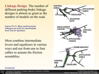
The document provides information about parking brake systems, including:
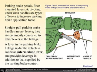
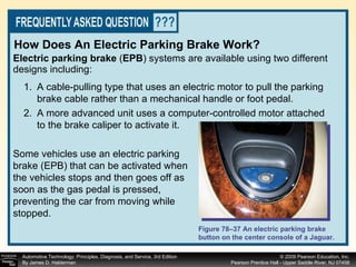
- Parking brakes are required to hold a vehicle stationary on a 20% grade and can use drum or disc brake systems.
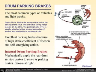
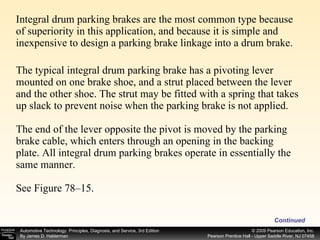
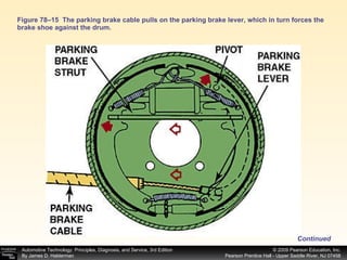
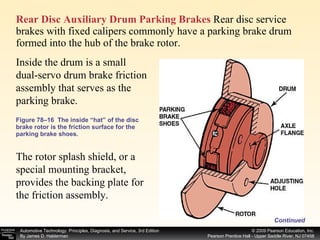
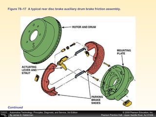
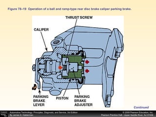
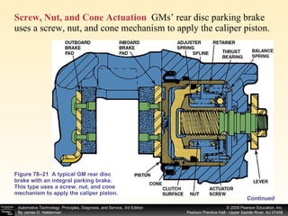
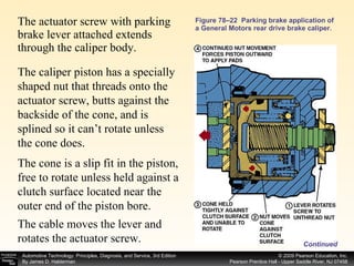
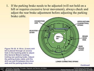
- Drum parking brakes typically use a lever and strut to apply both shoes, while disc systems may use the caliper.
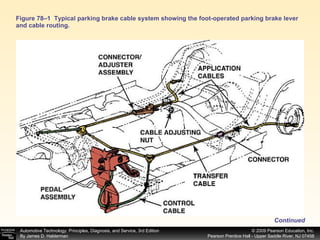
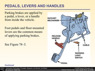
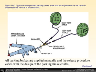
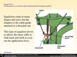
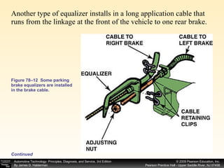
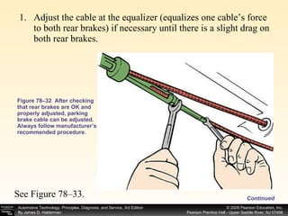
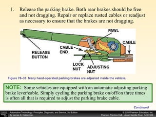
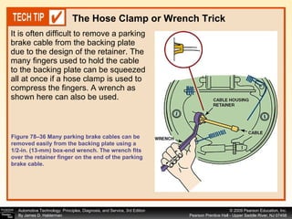
- Linkages include cables, rods, levers, and equalizers to evenly apply force to both sides.
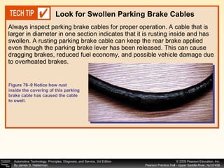
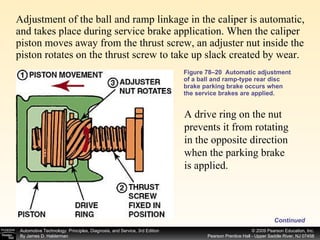
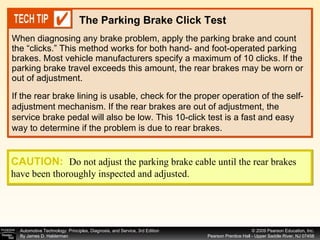
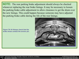
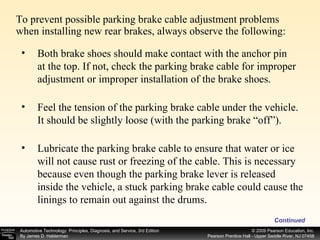
- Systems must be properly adjusted and inspected for wear like swollen cables.