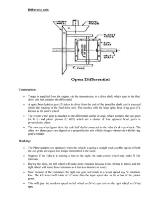
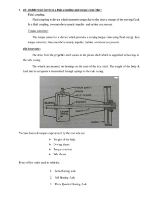
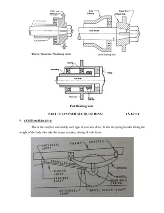
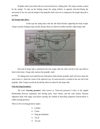
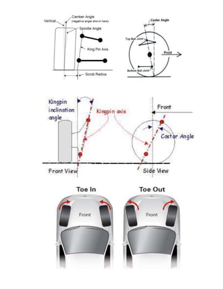
VIP Call Girls Service Kondapur Hyderabad Call +91-8250192130
Cia 2- ae - answer key
1. DEPARTMENT OF MECHANICAL ENGINEERING
CONTINUOUS INTERNAL ASSESSMENT - II
ACADEMIC YEAR 2017 -2018 EVEN SEMESTER
ANSWER KEY
Course Code & Title: ME6602 & Automobile engineering Date: 06.03.2018
Year/Branch/section:III / Mechanical / A, B & C Session & Duration: FN& 1½hrs
Semester: VI Max.Marks: 50
PART – A (ANSWER ALL QUESTIONS) 6 X 2 =12
1. Causes ofaxle failures:
Overloading of vehicle
Entry of dust or abrasive particles in the axle
The lubrication is not maintained at the required level
The replaced parts are not of the correct type
Usage of incorrect grade lubrication
2. Slip joint in transmission system:
A slip joint is used between a propeller shaft and universal joint connecting the propeller shaft to
compensate the change in length and it helps to transmit power from the engine to the rear axle at the
same time.
3. Universal joint in a propeller shaft:
It is used to connect gear box shaft and differential unit through a propeller shaft and provides
angular power transmission of rotary motion.
4. Advantages ofoverdrive:
It allows a lower engine speed to maintain the car at highway speed
It does not require as much power to keep it moving. Therefore, the engine can turn more
slowly, produce less power and still maintain car speed.
This system saves fuel
Wear on the engine and accessories are reduced
5. Ackermann steering principle:
This linkage is based on a four bar chain with two longer links of unequal lengths with two
shorter links of equal lengths. The mechanism is simple. When the vehicle is running along a straight
path, the longer links will become parallel and each of the shorter links will be inclined at an angle α
to the longitudinal axis of the vehicle.
6. Turning radius:
The radius of the circle on which the outside front wheel travels when the front wheels turn to
their extreme outer position is called turning radius.
2. PART – B (ANSWER ALL QUESTIONS) 2 X 12 =24
7. (A) single plate clutch:
A single plate is commonly used in cars and light vehicles. It has only one clutch plate which is
mounted on the splines of the clutch shaft. A flywheel is mounted on the crankshaft of the engine. A
pressure plate is connected to the flywheel through the bolts and clutch springs. It is free to slide on
the clutch shaft with the movement of clutch pedal.
When clutch is in engaged position, the clutch plate remains gripped between flywheel and
pressure plate. Friction linings are provided on both the sides of clutch plate. On one side clutch plate
is in touch with flywheel and on other side with pressure plate. Due to friction on both sides, the
clutch plate revolves with engine flywheel. Therefore, clutch transmits engine power to clutch shaft.
Clutch shaft is connected to transmission (or gear box) of automobile. Thus, clutch transmits power
from engine to transmission system which in turn rotates wheels of engine.
When the clutch plate is to be disengaged, the clutch pedal is pressed. Because of this pressure
plate moves back and clutch plate is disengaged from flywheel. Thus, clutch shaft stops rotating even
if engine flywheel is rotating. In this position, power does not reach the wheels and vehicle also stops
running.
7. (B) constant mesh gear box:
In this v type of gearbox, all the gears of the main shaft are in constant mesh with corresponding
gears of the countershaft. The gears on the main shaft which are bushed are free to rotate. The dog
clutches are provided on main shaft. The gears on the lay shaft are,however, fixed.
3. When the left Dog clutch is slid to the left by means of the selector mechanism, its teeth are
engaged with those on the clutch gear and we get the direct gear. The same dog clutch, however,
when slid to right makes contact with the second gear and second gear is obtained.
Similarly movement of the right dog clutch to the left results in low gear and towards right in
reverse gear. Usually the helical gears are used in constant mesh gearbox for smooth and noiseless
operation.
8. (A) Needs For Differential Unit:
Car wheels spin at different speeds, especially when turning, each wheel travels a different
distance through the turn, and the inside wheels travel a shorter distance than the outside
wheels. Since speed is equal to the distance travelled divided by the time it takes to go that
distance, the wheels that travel a shorter distance travel at a lower speed.
For the non-driven wheels on a car this is not an issue, as there is no connection between
them, so they spin independently. But the driven wheels are linked together so that a single
engine and transmission can turn both wheels.
If the car did not have a differential, the wheels would have to be locked together, forced to
spin at the same speed. This would make turning difficult and hard on the car. For the car to
be able to turn, one tire would have to slip. A great amount of force is required to make a tire
slip, putting a heavy strain on the axle components.
The differential is a device that splits the engine torque two ways, allowing each output to
spin at a different speed.
4. Differential unit:
Construction:
Torque is supplied from the engine, via the transmission, to a drive shaft, which runs to the final
drive unit that contains the differential.
A spiral bevel pinion gear (P) takes its drive from the end of the propeller shaft, and is encased
within the housing of the final drive unit. This meshes with the large spiral bevel ring gear (C),
known as the crown wheel.
The crown wheel gear is attached to the differential carrier or cage, which contains the sun gears
(A & B) and planet pinions (C &D), which are a cluster of four opposed bevel gears in
perpendicular plane.
The two sun wheel gears drive the axle half shafts connected to the vehicle's driven wheels. The
other two planet gears are aligned on a perpendicular axis which changes orientation with the ring
gear's rotation.
Working:
The Planet pinions are stationary when the vehicle is going a straight road, and the speeds of both
the sun gears are equal, thus torque transmitted is the same.
Suppose if the vehicle is making a turn to the right, the main crown wheel may make N full
rotations.
During that time, the left wheel will make more rotations because it has further to travel, and the
right wheel will make fewer rotations as it has less distance to travel.
Now because of the resistance, the right sun gear will rotate at a lesser speed, say ‘n’ rotations
less. The left wheel will rotate at ‘n’ more than the input speed due to the action of the pinion
gears.
This will give the resultant speed on left wheel as (N+n) rpm and on the right wheel as (N+n)
rpm.
5. 8. (B) (i) difference between a fluid coupling and torque converter:
Fluid coupling:
Fluid coupling is device which transmits torque due to the kinetic energy of the moving fluid.
In a fluid coupling, two members namely impeller and turbine are present.
Torque converter:
The torque converter is device which provides a varying torque ratio using fluid energy. In a
torque converter, three members namely impeller, turbine and stator are present.
(ii) Rear axle:
The drive from the propeller shaft comes to the pinion shaft which is supported in bearings in
the axle casing.
The wheels are mounted on bearings on the ends of the axle shaft. The weight of the body &
load due to occupants is transmitted through springs to the axle casing.
Various forces & torques experienced by the rear axle are
Weight of the body
Driving thrust
Torque reaction
Side thrust
Types of live axles used in vehicles:
1. Semi-floating axle
2. Full floating Axle
3. Three Quarter Floating Axle
6. PART – C (ANSWER ALL QUESTIONS) 1 X 14 =14
9. (A)(i)Hotchkiss drive:
This is the simplest and widely used type of rear axle drive. In this the spring besides taking the
weight of the body also take the torque reaction, driving & side thrust.
7. Propeller shaft is provided with two universal joints & a sliding joint. The torque reaction is taken
by the springs. To take up the braking torque the spring deflects in opposite direction.During the
movement of the rear axle the length of the propeller shaft varies & to compensate the length slip joint is
provided.
(ii) Torque tube drive:
In this type the spring takes only the side thrust besides supporting the body weight.
Torque reaction, braking torque and the driving thrust are taken by another member called torque tube.
One end of torque tube is attached to the axle casing while the other end fits in the cup which is
fixed to the frame. Torque tube encloses the propeller shaft.
No sliding joint is provided because both pinion shaft and the propeller shaft will move about the
same centre i.e. about the centre of the spherical cup. No universal joint is needed at the rear end of the
propeller shaft. Torque reaction & the driving thrust are taken by the torque tube.
9 (b) Steering Geometry:
The term "steering geometry" (also known as "front-end geometry") refers to the angular
Relationship between suspension and steering parts, front wheels, and the road surface. Because
alignment deals with angles and affects steering, the method of describing alignment measurements is
called steering geometry.
There are five steering geometry angles:
Camber
Caster
King pin inclination
Toe in
Toe-out