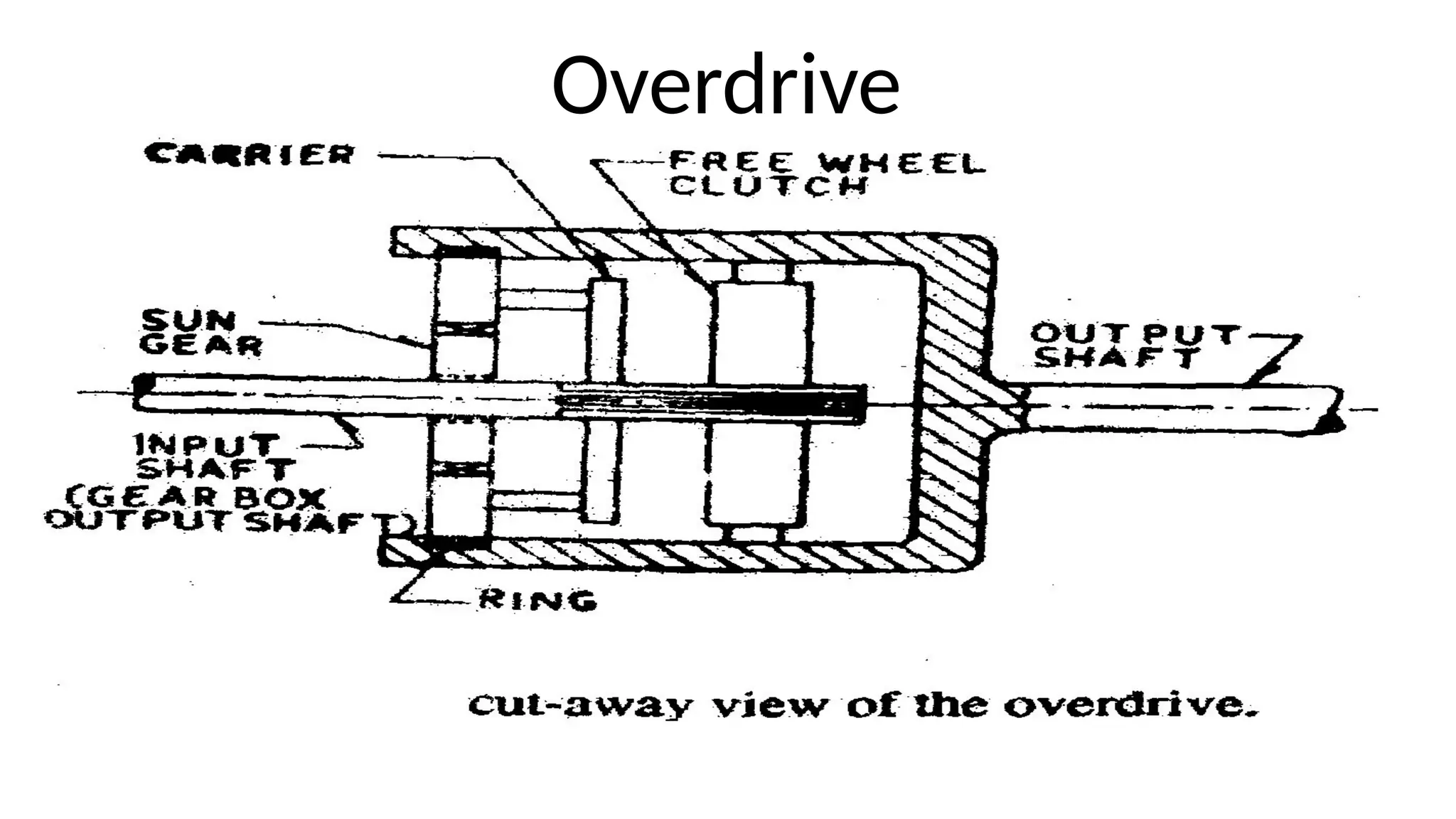
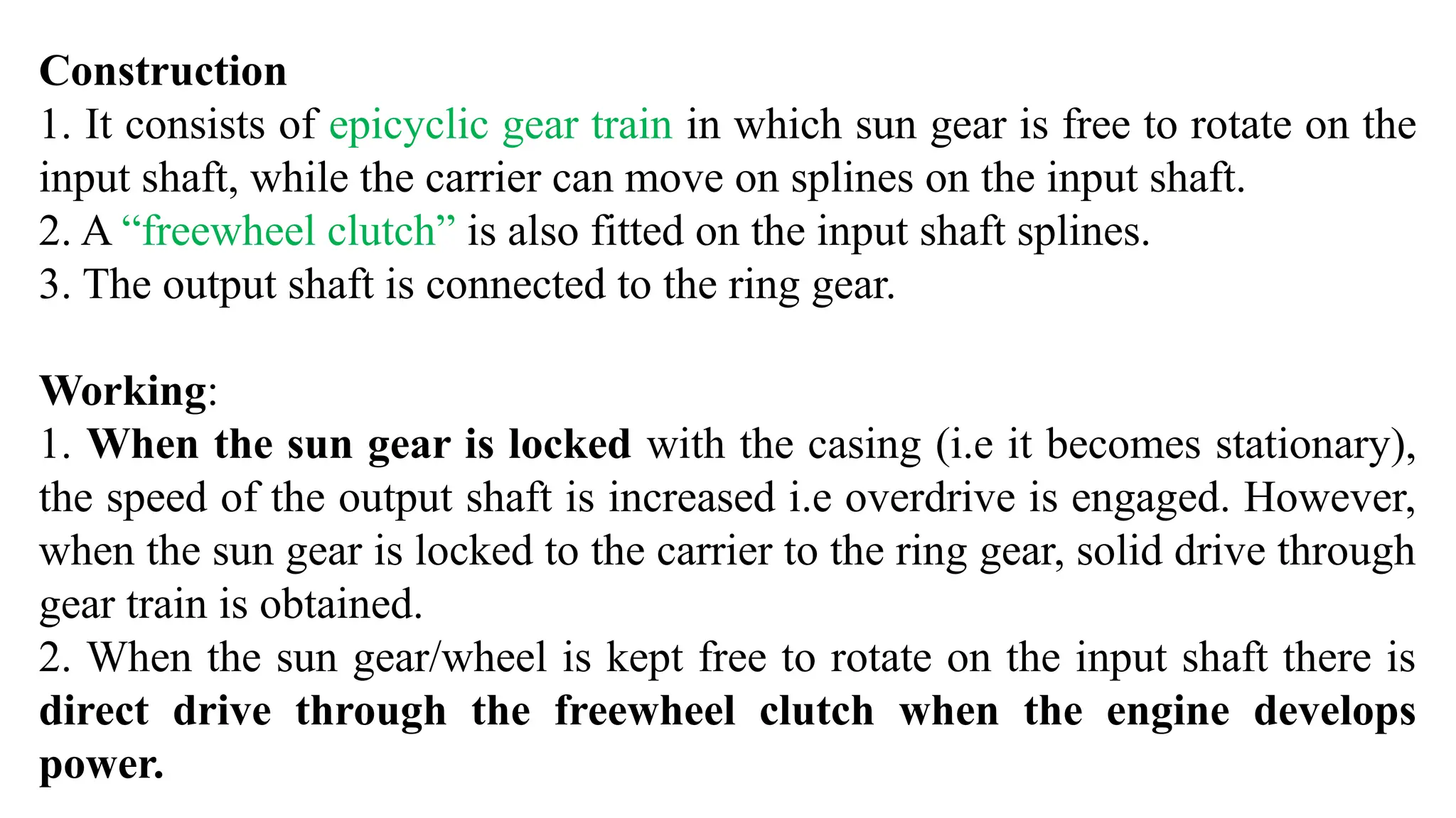
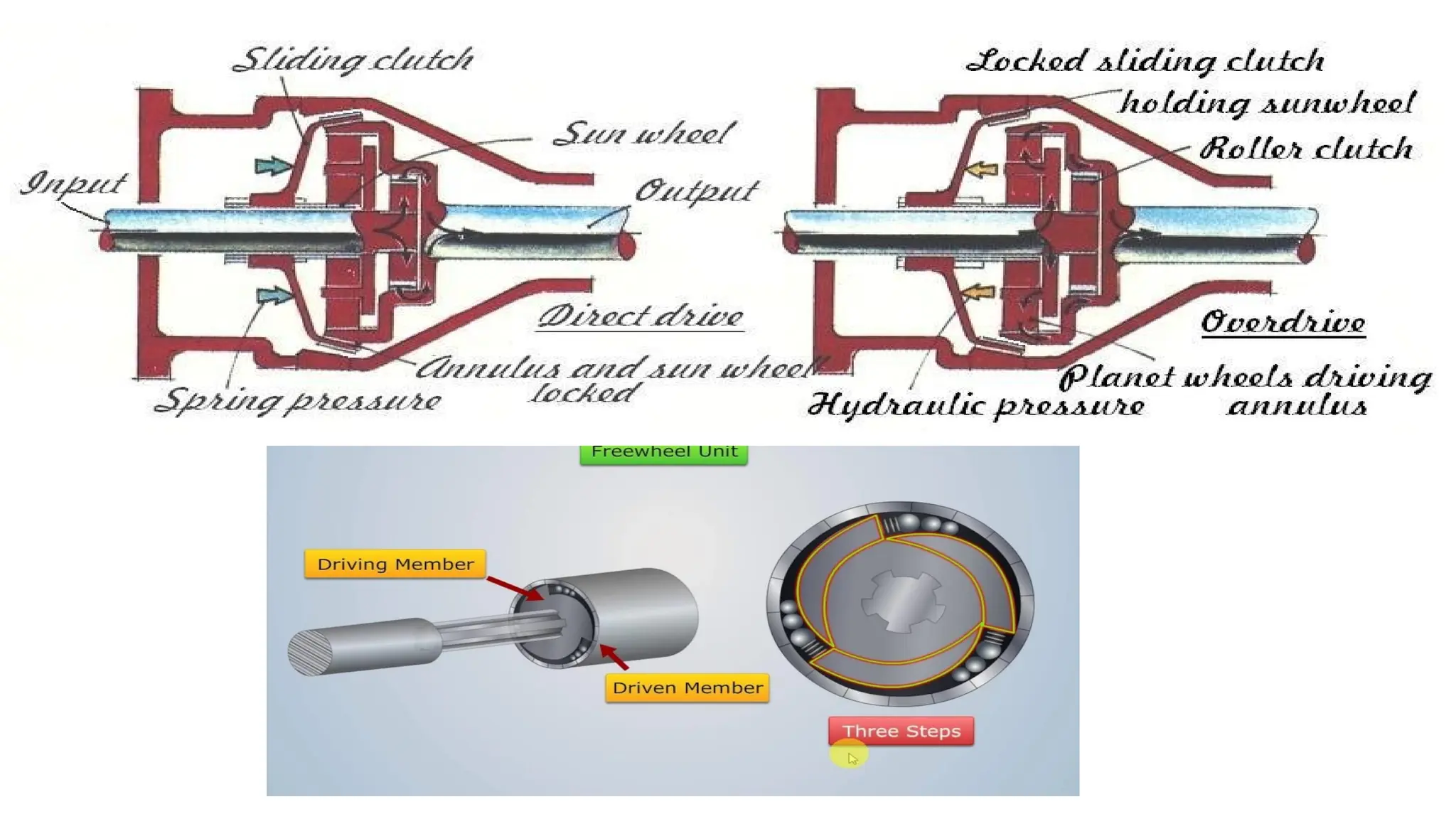
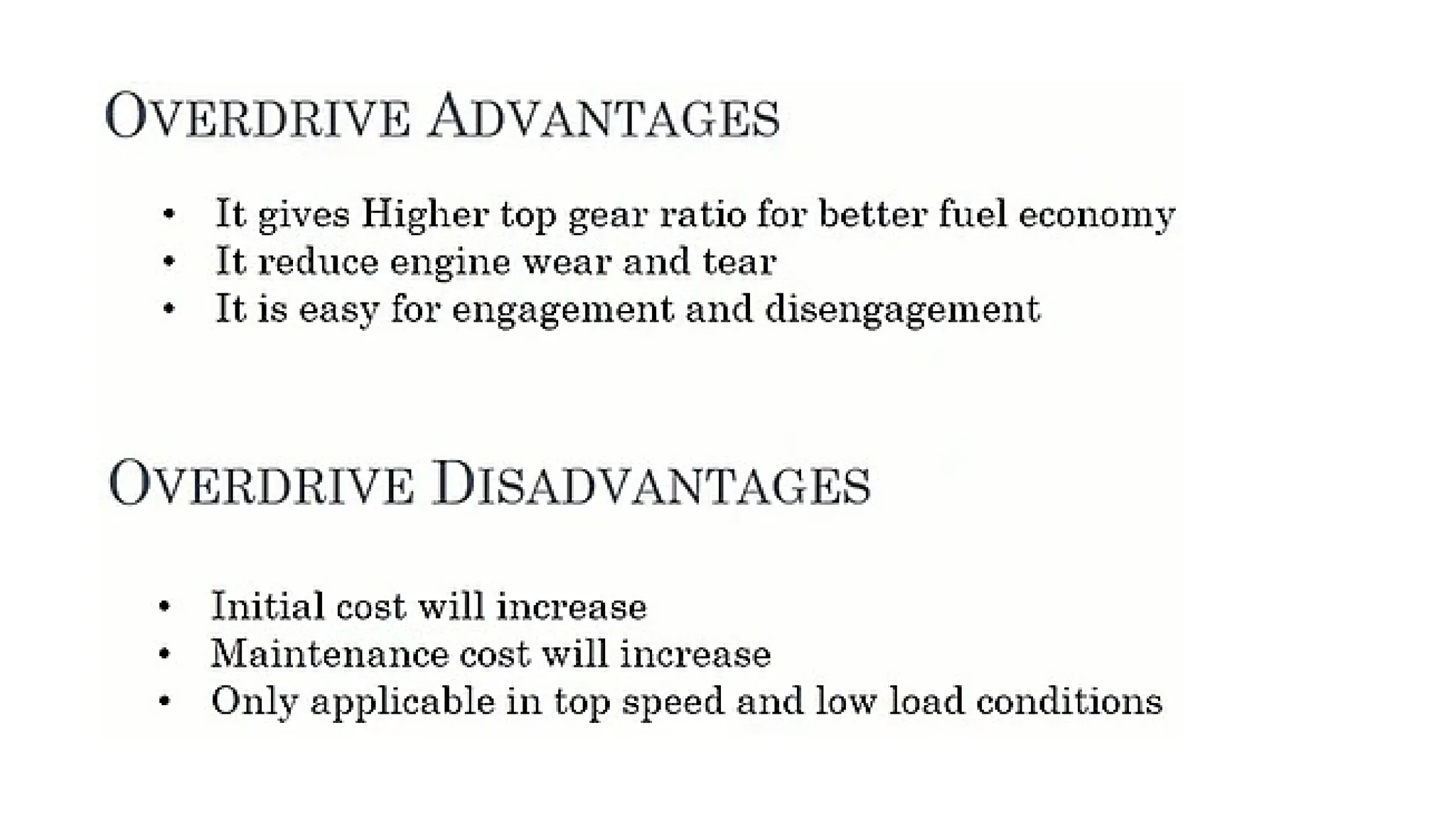
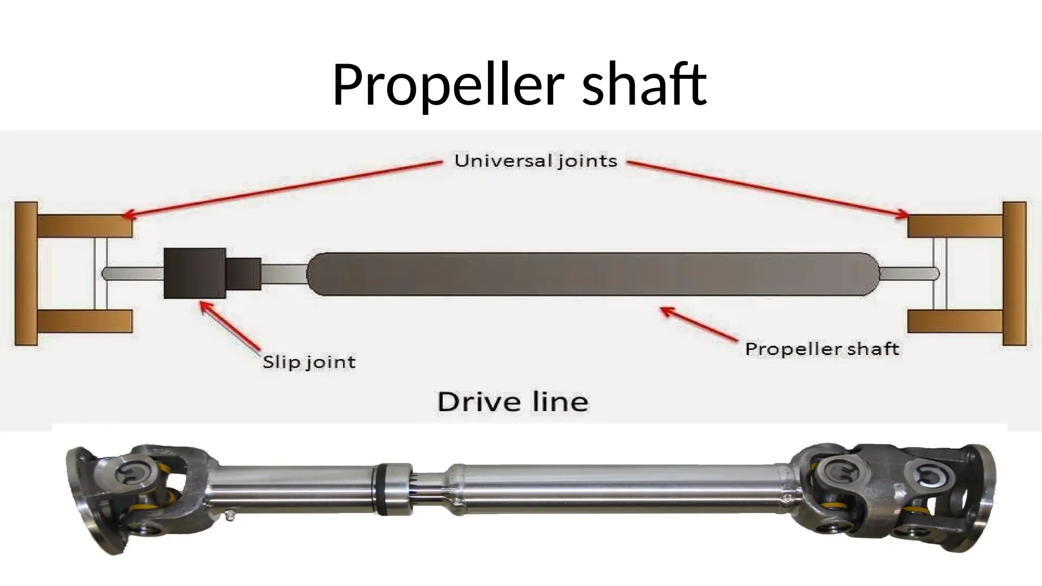
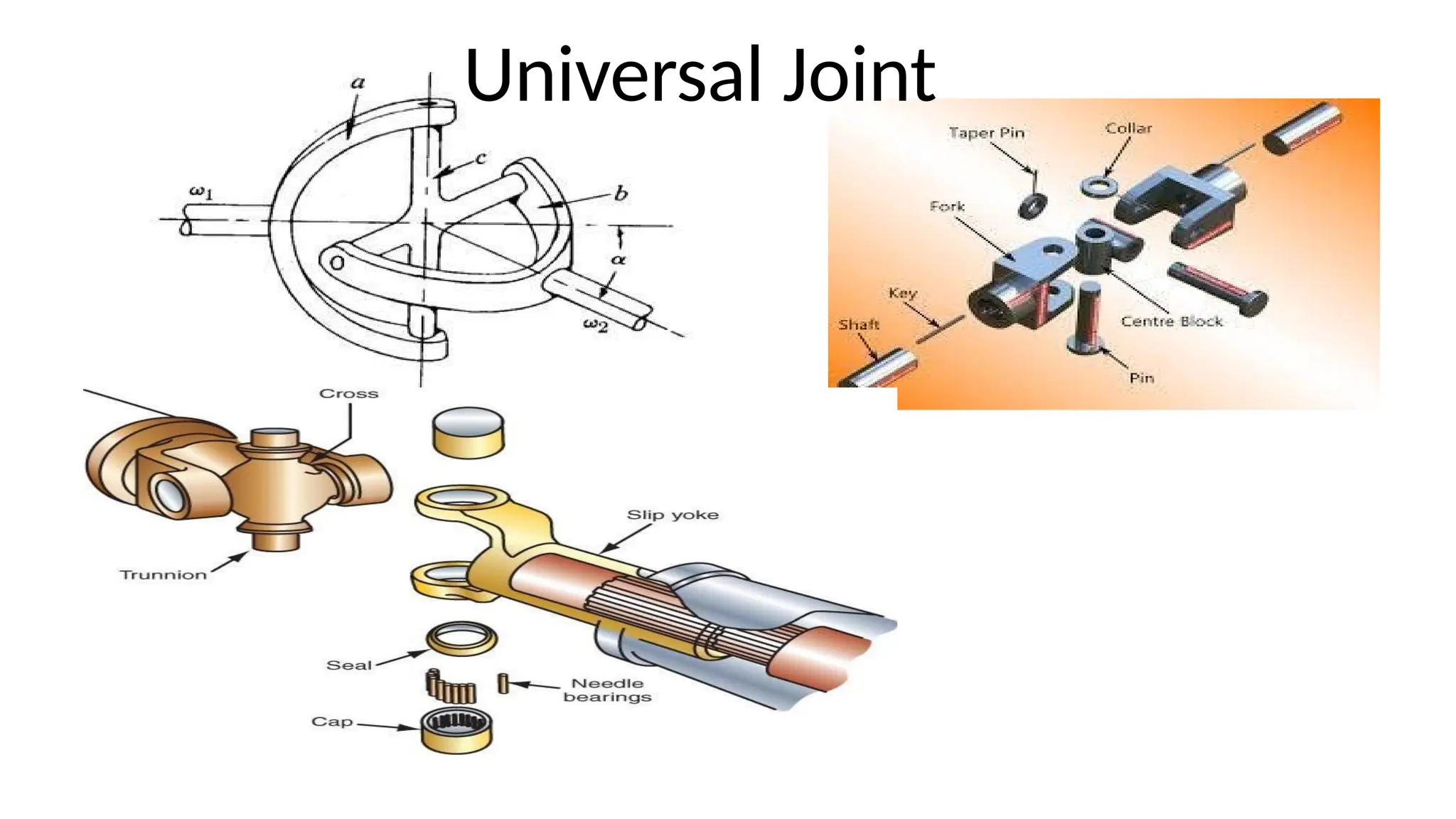
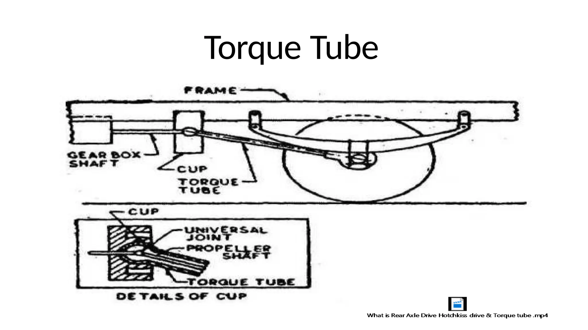
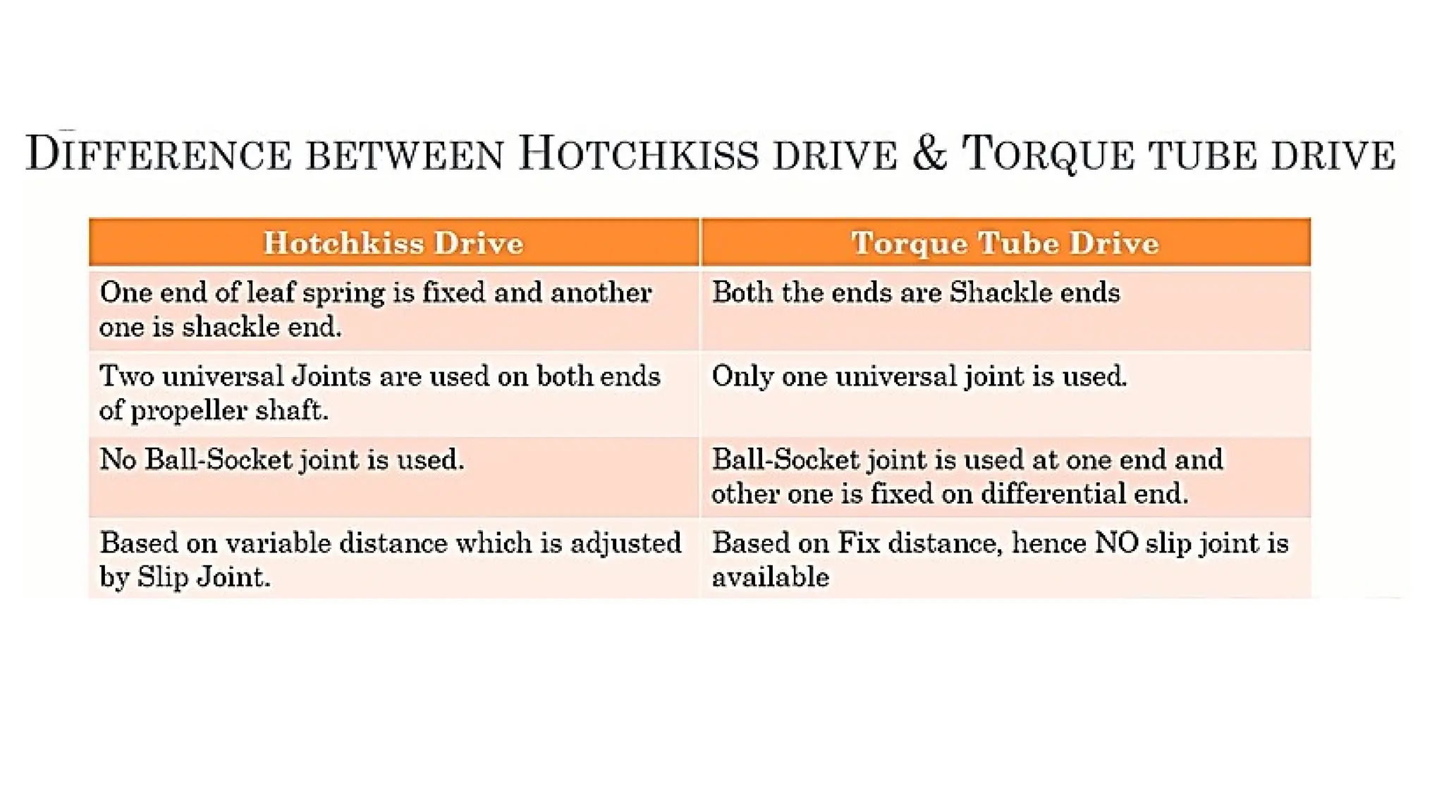
Unit 1 Drive Train –Overdrive
Prof Rohit Bhaskar
Department of Mechanical
Engineering
Automobile Engineering
Overdrive
1. Overdrive is a device interposed between the transmission (gear box) and propeller shaft.
2. Overdrive permits the propeller shaft to turn faster than overdrive and main
transmission shaft.
3. The term “Overdrive” means it provides a speed ratio over that of higher speed ratio.
Function of Overdrive
1. The overdrive permits the engine to operate only about 70% of the propeller shaft speed,
when the vehicle is operating at high speed range.
2. The overdrive is generally used for high powered cars employing three speed gear box in
order to produce flexible top gear performance.
3. Generally Overdrive is fitted to the top gear only, but some sport cars have an overdrive
on 2nd
, 3rd
and top gear giving seven forward speeds.
4. Overdrive is usually employed to supplement conventional transmission. It is bolted to the
rear of the transmission between transmission and propeller shaft.
5. A slightly higher rear axle gear ratio is employed with an overdrive than without one.
Introduction
Overdrive
Construction
1. It consists of epicyclic gear train in which sun gear is free to rotate on the
input shaft, while the carrier can move on splines on the input shaft.
2. A “freewheel clutch” is also fitted on the input shaft splines.
3. The output shaft is connected to the ring gear.
Working:
1. When the sun gear is locked with the casing (i.e it becomes stationary),
the speed of the output shaft is increased i.e overdrive is engaged. However,
when the sun gear is locked to the carrier to the ring gear, solid drive through
gear train is obtained.
2. When the sun gear/wheel is kept free to rotate on the input shaft there is
direct drive through the freewheel clutch when the engine develops
power.
Propeller shaft
Propeller shaft
Propeller Shaft
• Shaft
– Withstand torsional load
– Well balanced to avoid whirling at high speed
– Steel, Al or composite material
• Universal Joint
– Accounts up and down motion of the rear axle
– Cardon joints- high speed constant velocity joint with the option of
intermediate bearing ,limited slip devices and crash feature
• Slip Joint
– Adjust the length of the propeller shaft
https://youtu.be/y8QaD8NJLxM
• Whirling effect
1. Increase in dia
2. Critical speed is inversely proportional to
square of length of shaft
3. Divided shafts with internal bearings
Propeller Shaft
Universal Joint
Flexible ring universal coupling
Spider
Limitation: Variation in the speed of the driven shaft at various inclination
Remedies: Use of two universal Joint
Constant velocity joint
• Generally used for front wheel drive
• Two types
• Fixed type (outboard): at wheel end
• Plunging types (inboard): at differential end
Axle shaft
Transmits power from inner to outer CV-joint
Rzeppa Joint - Exploded View
Rzeppa CV
Rzeppa Joint - Exploded View
Tripod Joint
Final Drive
•Final drive is the last stage of power transfer from propeller shaft to
rear (or front if – automobile is front wheel driven) axles and then to
wheels. It turns the propeller shaft motion at right angle to drive the
rear axle.
•Consists of Bevel pinion and crown wheel or worm and worm wheel
arrangement
•Bevel gear=propeller shaft
•Crown wheel drive goes to the differential
•Three Types of the gears are used
•Straight Bevel Gears
(uneven transfer of motion)
•Spiral bevel gears
•Hypoid bevel gears
Differential
Pinion Drive Gear: transfers power from the
driveshaft to the ring gear.
Ring Gear: transfers power to the
Differential case assembly.
Side/spider gears: help both wheels to turn
independently when turning.
Differential case assembly: holds the
Ring gear and other components that drive the
rear axle.
Rear drive axles: steel shafts that transfer torque
from the differential assembly to the
drive wheels.
Rear axle bearings: ball or roller bearings that fit between the axles and the inside of the axle housing.
Power flow
•Drive shaft spins the Pinion gear.
•Pinion gear turns the larger ring gear to produce gear
reduction.
•Ring gear attached to differential case, hence it
rotates with the ring gear.
•Differential case spins the sun gears which are
attached to the axles.
• Axles transfer the power to the wheels.
Function
•Transfers power from driveshaft to the wheels.
•Provides final gear reduction.
•Splits amount of torque going to each wheel.
•Allow the wheels to rotate at different speeds in turns.
Differential Gear box working
principle(Ref G B NARANG )
https://www.youtube.com/watch?v=SOgoejxzF8c&ab_channel=Lesics
https://www.youtube.com/watch?v=nC6fsNXdcMQ&ab_channel=Lesics
Hotchkiss Drive
• The Hotchkiss drive is a system of power
transmission
• Rear axle drive
• It was the dominant form of power
transmission for front-engine, rear-wheel drive
layout cars in the 20th century
• Requirement of mechanism to transfer driving and
braking efforts to chassis
Construction of Hotchkiss Drive
• Simplest and most widely used type of rear axle drive .
• The spring besides taking weight of the body also take the
torque reaction , driving thrust and side thrust .
• propellar shaft is provied with two universal joints
also a sliding joint .
• The front end of the spring is fixed rigidly on the frame while
the rear end and is supported in the shackle .
Torque Tube
Torque Tube
References
1. K. Newton and W. Seeds, T.K. Garrett, “Motor Vehicle” 13th Edition,
Elsevier publications
2. Hans Hermann Braess, Ulrich Seiffen, handbook of Automotive
Engineering, SAE Publications
3. William H. Crouse.,”Automotive Mechanics„ - Tata McGraw Hill
Publishing House
4. Joseph Heitner,”Automotive Mechanics„ -C.B.S Publishers And
Distributors
5. SAE Manuals and Standard
6. Automobile Mechanics -.N. K. Giri
7. Automobile Electrical Equipment -P. S. Kohali
8. Narang G. B. S , “Automobile Engineering” - S. Chand and Company
Ltd.
9. Singh Kripal - Automobile Engineering -Volume 2 New Chand Jain.

Lect 6 Unit 1 Drive Train Overdrive Overdrive

  • 1.
    Unit 1 DriveTrain –Overdrive Prof Rohit Bhaskar Department of Mechanical Engineering Automobile Engineering
  • 2.
  • 3.
    1. Overdrive isa device interposed between the transmission (gear box) and propeller shaft. 2. Overdrive permits the propeller shaft to turn faster than overdrive and main transmission shaft. 3. The term “Overdrive” means it provides a speed ratio over that of higher speed ratio. Function of Overdrive 1. The overdrive permits the engine to operate only about 70% of the propeller shaft speed, when the vehicle is operating at high speed range. 2. The overdrive is generally used for high powered cars employing three speed gear box in order to produce flexible top gear performance. 3. Generally Overdrive is fitted to the top gear only, but some sport cars have an overdrive on 2nd , 3rd and top gear giving seven forward speeds. 4. Overdrive is usually employed to supplement conventional transmission. It is bolted to the rear of the transmission between transmission and propeller shaft. 5. A slightly higher rear axle gear ratio is employed with an overdrive than without one. Introduction
  • 4.
  • 5.
    Construction 1. It consistsof epicyclic gear train in which sun gear is free to rotate on the input shaft, while the carrier can move on splines on the input shaft. 2. A “freewheel clutch” is also fitted on the input shaft splines. 3. The output shaft is connected to the ring gear. Working: 1. When the sun gear is locked with the casing (i.e it becomes stationary), the speed of the output shaft is increased i.e overdrive is engaged. However, when the sun gear is locked to the carrier to the ring gear, solid drive through gear train is obtained. 2. When the sun gear/wheel is kept free to rotate on the input shaft there is direct drive through the freewheel clutch when the engine develops power.
  • 8.
  • 9.
  • 10.
    Propeller Shaft • Shaft –Withstand torsional load – Well balanced to avoid whirling at high speed – Steel, Al or composite material • Universal Joint – Accounts up and down motion of the rear axle – Cardon joints- high speed constant velocity joint with the option of intermediate bearing ,limited slip devices and crash feature • Slip Joint – Adjust the length of the propeller shaft https://youtu.be/y8QaD8NJLxM
  • 11.
    • Whirling effect 1.Increase in dia 2. Critical speed is inversely proportional to square of length of shaft 3. Divided shafts with internal bearings Propeller Shaft
  • 12.
  • 13.
    Flexible ring universalcoupling Spider Limitation: Variation in the speed of the driven shaft at various inclination Remedies: Use of two universal Joint
  • 14.
    Constant velocity joint •Generally used for front wheel drive • Two types • Fixed type (outboard): at wheel end • Plunging types (inboard): at differential end
  • 16.
    Axle shaft Transmits powerfrom inner to outer CV-joint
  • 17.
    Rzeppa Joint -Exploded View
  • 18.
  • 19.
    Rzeppa Joint -Exploded View
  • 20.
  • 21.
    Final Drive •Final driveis the last stage of power transfer from propeller shaft to rear (or front if – automobile is front wheel driven) axles and then to wheels. It turns the propeller shaft motion at right angle to drive the rear axle. •Consists of Bevel pinion and crown wheel or worm and worm wheel arrangement •Bevel gear=propeller shaft •Crown wheel drive goes to the differential •Three Types of the gears are used •Straight Bevel Gears (uneven transfer of motion) •Spiral bevel gears •Hypoid bevel gears
  • 22.
    Differential Pinion Drive Gear:transfers power from the driveshaft to the ring gear. Ring Gear: transfers power to the Differential case assembly. Side/spider gears: help both wheels to turn independently when turning. Differential case assembly: holds the Ring gear and other components that drive the rear axle. Rear drive axles: steel shafts that transfer torque from the differential assembly to the drive wheels. Rear axle bearings: ball or roller bearings that fit between the axles and the inside of the axle housing.
  • 23.
    Power flow •Drive shaftspins the Pinion gear. •Pinion gear turns the larger ring gear to produce gear reduction. •Ring gear attached to differential case, hence it rotates with the ring gear. •Differential case spins the sun gears which are attached to the axles. • Axles transfer the power to the wheels.
  • 24.
    Function •Transfers power fromdriveshaft to the wheels. •Provides final gear reduction. •Splits amount of torque going to each wheel. •Allow the wheels to rotate at different speeds in turns.
  • 25.
    Differential Gear boxworking principle(Ref G B NARANG ) https://www.youtube.com/watch?v=SOgoejxzF8c&ab_channel=Lesics https://www.youtube.com/watch?v=nC6fsNXdcMQ&ab_channel=Lesics
  • 26.
    Hotchkiss Drive • TheHotchkiss drive is a system of power transmission • Rear axle drive • It was the dominant form of power transmission for front-engine, rear-wheel drive layout cars in the 20th century • Requirement of mechanism to transfer driving and braking efforts to chassis
  • 28.
    Construction of HotchkissDrive • Simplest and most widely used type of rear axle drive . • The spring besides taking weight of the body also take the torque reaction , driving thrust and side thrust . • propellar shaft is provied with two universal joints also a sliding joint . • The front end of the spring is fixed rigidly on the frame while the rear end and is supported in the shackle .
  • 31.
  • 32.
  • 34.
    References 1. K. Newtonand W. Seeds, T.K. Garrett, “Motor Vehicle” 13th Edition, Elsevier publications 2. Hans Hermann Braess, Ulrich Seiffen, handbook of Automotive Engineering, SAE Publications 3. William H. Crouse.,”Automotive Mechanics„ - Tata McGraw Hill Publishing House 4. Joseph Heitner,”Automotive Mechanics„ -C.B.S Publishers And Distributors 5. SAE Manuals and Standard 6. Automobile Mechanics -.N. K. Giri 7. Automobile Electrical Equipment -P. S. Kohali 8. Narang G. B. S , “Automobile Engineering” - S. Chand and Company Ltd. 9. Singh Kripal - Automobile Engineering -Volume 2 New Chand Jain.