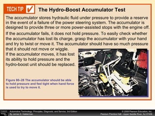
The document provides information about vacuum brake boosters, including:
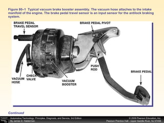
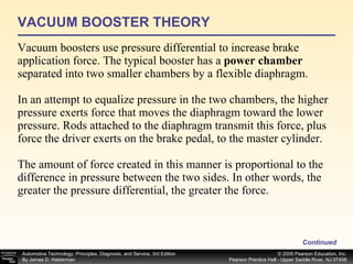
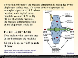
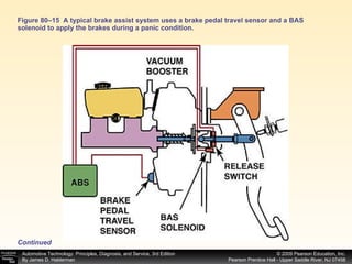
- Vacuum brake boosters use engine intake manifold vacuum and pressure differential to multiply brake pedal force applied by the driver.
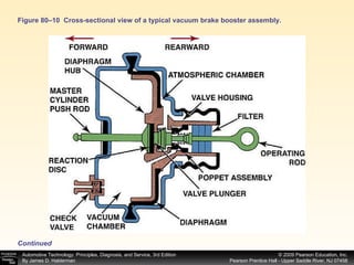
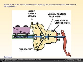
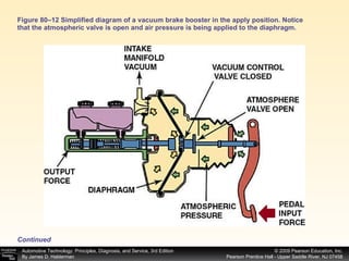
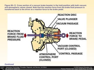
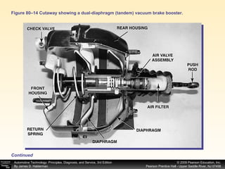
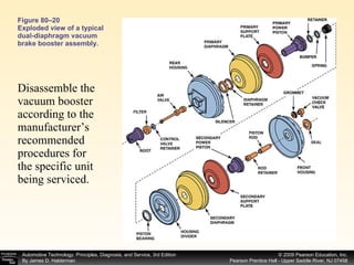
- They contain one or two rubber diaphragms connected to the brake pedal and master cylinder. Opening an atmospheric valve allows air pressure to assist braking.
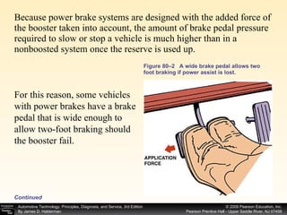
- Vacuum boosters are tested by depleting vacuum stored in the booster and ensuring the brake pedal drops when the engine is restarted, indicating restored vacuum power assist.