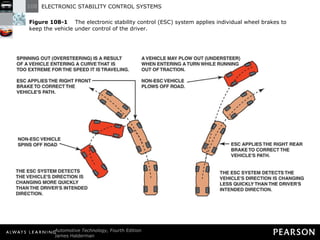
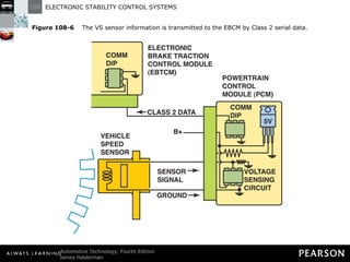
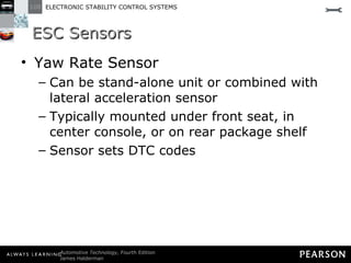
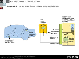
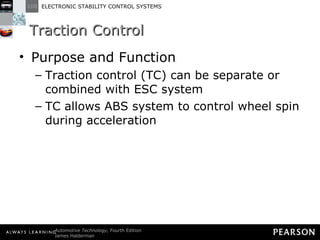
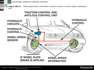
ELECTRONIC STABILITY CONTROL SYSTEMS 108
Objectives The student should be able to: Prepare for Brakes (A5) ASE certification test content area “F” (Antilock Brake System Diagnosis and Repair).  Discuss how an electronic stability system works. List the sensors needed for the ESC system.
Objectives The student should be able to: Explain how the ESC system helps keep the vehicle under control.  Describe how a traction control system works. List the steps in the diagnostic process for ESC and TC system faults.
THE NEED FOR ELECTRONIC STABILITY CONTROL
The Need for Electronic Stability Control Purpose and Function Electronic stability control (ESC) is system designed to help drivers keep control of their cars Helps prevent run-off-road crashes and rollovers
The Need for Electronic Stability Control System Requirements ESC has the following features: Applies individual brakes to maintain directional stability.
The Need for Electronic Stability Control System Requirements ESC has the following features: Uses sensors to determine if vehicle is not under control.
The Need for Electronic Stability Control System Requirements ESC has the following features: Uses steering wheel position sensor to determine intended direction.
The Need for Electronic Stability Control System Requirements ESC has the following features: Operates at all vehicle speeds except low speeds.
The Need for Electronic Stability Control System Requirements ESC applies individual brakes if either of these conditions occur: Oversteering: rear of vehicle moves outward or breaks loose Can result in loss of control
The Need for Electronic Stability Control System Requirements ESC applies individual brakes if either of these conditions occur: Understeering: front of vehicle continues straight when turning
Figure 108-1   The electronic stability control (ESC) system applies individual wheel brakes to keep the vehicle under control of the driver.
The Need for Electronic Stability Control System Requirements NOTE: When the brakes are applied during these corrections, a thumping sound and vibration may be sensed.
The Need for Electronic Stability Control System Requirements ESC lamp—called telltale lamp—remains on as long as malfunction exists when ignition is on Telltale lamp flashes to indicate when ESC system is operating
The Need for Electronic Stability Control System Requirements Some manufacturers install switch to temporarily disable ESC Feature useful on certain occasions When a vehicle is stuck in sand or gravel
The Need for Electronic Stability Control System Requirements Feature useful on certain occasions When vehicle is being operated on racetrack
The Need for Electronic Stability Control System Requirements ESC automatically turns back on when ignition is turned off and then on again
FEDERAL MOTOR VEHICLE SAFETY STANDARD (FMVSS) NO. 126
Federal Motor Vehicle Safety Standard (FMVSS) No. 126 FMVSS, Electronic Stability Control Systems, requires all passenger vehicles with gross vehicle weight rating less than 10,000 pounds to have ESC systems by 2012 model year
Federal Motor Vehicle Safety Standard (FMVSS) No. 126 ESC system must meet these requirements: Must be able to apply all four brakes independently. Acceleration
Federal Motor Vehicle Safety Standard (FMVSS) No. 126 ESC system must meet these requirements: Must be programmed to work during all phases of driving.  Coasting
Federal Motor Vehicle Safety Standard (FMVSS) No. 126 ESC system must meet these requirements Must be programmed to work during all phases of driving.  Deceleration (including braking)
SINE WITH DWELL TEST
Sine with Dwell Test Standardized test to check ESC system functionality is sine with dwell (SWD) test Vehicle driven at 50 mph (80 km/h) on curved course Vehicle is held in straight ahead position for 0.5 second (500 milliseconds)
Sine with Dwell Test Standardized test to check ESC system functionality is sine with dwell (SWD) test Vehicle is then steered back onto curved section of road Test designed to force vehicle ESC system to respond
Figure 108-2   The sine with dwell test is designed to test the electronic stability control (ESC) system to determine if the system can keep the vehicle under control.
NAMES OF VARIOUS ESC SYSTEMS
Names of Various ESC Systems Every manufacturer has its own name for the ESC system Some examples include the following: BMW: Dynamic Stability Control (DSC)
Names of Various ESC Systems Some examples include the following: Chrysler: Electronic Stability Program (ESP) Ford: AdvanceTrac and Interactive Vehicle Dynamics (IVD)
Names of Various ESC Systems Some examples include the following: General Motors: StabiliTrak (except Corvette—Active Handling) Jeep: Electronic Stability Program (ESP) Toyota: Vehicle Dynamics Integrated Management (VDIM) with Vehicle Stability Control (VSG) ?
ESC SENSORS
ESC Sensors Steering Wheel Position Sensor May also be called a hand-wheel position sensor Provides computer with signals related to steering wheel position, speed, and direction
Figure 108-4   The hand-wheel position sensor is usually located at the base of the steering column.
Figure 108-5   Hand-wheel (steering wheel) position sensor schematic.
ESC Sensors Vehicle Speed Sensor Used by Electronic Brake Control Module to help control suspension system Vehicle speed (VS) sensor is magnetic sensor VS sensor generates analog signal whose frequency increases as speed increases
Figure 108-6   The VS sensor information is transmitted to the EBCM by Class 2 serial data.
ESC Sensors Lateral Acceleration Sensor Provides suspension control module with feedback regarding cornering forces This type of sensor called G-sensor
ESC Sensors Lateral Acceleration Sensor Letter “G” stands for gravity Information processed by suspension control module
ESC Sensors Lateral Acceleration Sensor Module provides appropriate damping on inboard and outboard dampers during cornering events This sensor can be stand-alone unit or combined with yaw rate sensor
ESC Sensors Lateral Acceleration Sensor Typically mounted in passenger compartment: Under front seat
ESC Sensors Lateral Acceleration Sensor Typically mounted in passenger compartment: In center console
ESC Sensors Lateral Acceleration Sensor Typically mounted in passenger compartment: On package shelf
Figure 108-7   A schematic showing the lateral acceleration sensor and EBCM.
ESC Sensors Yaw Rate Sensor Provides information to suspension control module and EBCM Information used to determine how far vehicle has deviated from intended direction
ESC Sensors Yaw Rate Sensor Can be stand-alone unit or combined with lateral acceleration sensor Typically mounted under front seat, in center console, or on rear package shelf Sensor sets DTC codes
Figure 108-9   Yaw rate sensor showing the typical locations and schematic.
TRACTION CONTROL
Traction Control Purpose and Function Traction control (TC) can be separate or combined with ESC system TC allows ABS system to control wheel spin during acceleration
Traction Control Purpose and Function When tires lose traction during acceleration it’s called positive slip Low-speed (up to 30 mph) TC uses braking system to limit positive slip
Figure 108-10   Typical traction control system that uses wheel speed sensor information and the engine controller (PCM) to apply the brakes at lower speeds and also reduce engine power applied to the drive wheels.
Traction Control  Purpose and Function TC uses same wheel speed sensors as ABS Requires additional programming in control module
Traction Control  Purpose and Function TC also requires Additional solenoids in hydraulic modulator Needed to isolate non-drive wheels from drive wheels when braking is needed to control wheel spin
Traction Control  Purpose and Function TC also requires Pump and accumulator to generator and store pressure for TC braking TC works on front-wheel-drive and rear-wheel-drive vehicles
Traction Control  System Components Main controller for TC system includes one of following: Body control module (BCM)
Traction Control  System Components Main controller for TC system includes one of following: Powertrain control module (PCM)
Traction Control  System Components Main controller for TC system includes one of following: Antilock brake system (ABS) controller
Traction Control  System Components Controller uses inputs from several sensors Throttle position (TP) sensor
Traction Control  System Components Controller uses inputs from several sensors Wheel speed sensor (WSS)
Traction Control  System Components Controller uses inputs from several sensors Engine speed (RPM)
Traction Control  System Components Controller uses inputs from several sensors Transmission range switch
Traction Control  Traction Control Operation Outputs of TC system can include one or more of the following: Retard ignition timing to reduce engine torque
Traction Control  Traction Control Operation Outputs of TC system can include one or more of the following: Decrease fuel injector pulse-width to reduce fuel delivery to reduce engine torque
Traction Control  Traction Control Operation Outputs of TC system can include one or more of the following: Reduce amount of intake air if engine is equipped with an electronic throttle control (ETC)  Reducing intake air will reduce engine torque
Traction Control  Traction Control Operation Outputs of TC system can include one or more of the following: Upshift the automatic transmission/transaxle Shifting into higher gear reduces torque
Traction Control  Traction Control Operation Most TC systems can reduce positive wheel slip at all speeds Most use accelerator reduction and engine power reduction to limit slip before applying brakes
Figure 108-11   Wheel speed sensor information is used to monitor if a drive wheel is starting to spin.
Traction Control Sequence of Events when TC system Engaged Engine torque reduced for drive wheels. Brakes applied to slow or stop wheel spinning. Low traction or TC warning light illuminated on dash.
Figure 108-12   A traction control or low traction light on the dash is confusing to many drivers. When the lamp is on or flashing, it indicates that a low traction condition has been determined and the traction control system is working to restore traction. A flashing traction dash light does not indicate a fault.
Traction Control Traction Active Lamp “ TRAC CNTL” indicator light or “TRACTION CONTROL ACTIVE” message flashes on instrumentation when TC engaged
Traction Control Traction Active Lamp Message alerts driver to loss of traction Message does not indicate a fault in system
Traction Control Traction Deactivation Switch Many vehicles have dash-mounted TC deactivation switch Indicator light shows when system is on or off ?
ESC/TC DIAGNOSIS
ESC/TC Diagnosis ESC and TC systems use some of same sensors and controllers Diagnosis is about the same for both Follow recommended procedures in service information
ESC/TC Diagnosis Usual procedure follows these steps: STEP 1: Verify customer concern. STEP 2: Perform thorough visual inspection. Check tires are same size and tread depth
ESC/TC Diagnosis Usual procedure follows these steps: STEP 2: Perform thorough visual inspection. NOTE: Use a spare tire on the drive wheel could cause the traction control and/or ESC amber warning light to flash because the controller is seeing that the smaller tire is rotating faster than the other side.
ESC/TC Diagnosis Usual procedure follows these steps: STEP 3: Check service information for specified procedure to retrieve DTCs. Check related technical service bulletins
ESC/TC Diagnosis Usual procedure follows these steps: STEP 3: Check service information for specified procedure to retrieve DTCs. Most vehicles require factory-brand scan tool
Figure 108-13   The use of a factory scan tool is often needed to diagnose the ESC system.
ESC/TC Diagnosis Usual procedure follows these steps: STEP 4: Following troubleshooting procedure specified to fix root cause of problem. Steps usually include checking all or many of the following: Brake fluid level
ESC/TC Diagnosis Usual procedure follows these steps: STEP 4: Following troubleshooting procedure specified to fix root cause of problem. Steps usually include checking all or many of the following: Wheel speed sensor resistance
ESC/TC Diagnosis Usual procedure follows these steps: STEP 4: Following troubleshooting procedure specified to fix root cause of problem. Steps usually include checking all or many of the following: Fault with base brake system
ESC/TC Diagnosis Usual procedure follows these steps: STEP 5: Repair the fault. STEP 6: Road test the vehicle under same conditions that caused the fault.
FREQUENTLY ASKED QUESTION Can a Vehicle with a Modified Suspension Pass the Test? Yes, if the system is properly engineered. To be sure, check with the company offering a suspension kit to verify that the vehicle will still be able to pass the sine with dwell (SWD) test. ? BACK TO  PRESENTATION This ensures that any changes are within the range where the ESC system can control the vehicle during emergency maneuvers. Figure 108-3   Using a simulator is the most cost-effective way for vehicle and aftermarket suspension manufacturers to check that the vehicle is able to perform within the FMVSS No. 126 standard for vehicle stability.
TECH TIP Quick and Easy Lateral Acceleration Sensor Test Most factory scan tools will display the value of sensors, including the lateral acceleration sensor. However, the sensor value will read zero unless the vehicle is cornering. A quick and easy test of the sensor is to simply unbolt the sensor and rotate it 90 degrees with the key on engine off. BACK TO  PRESENTATION Now the sensor is measuring the force of gravity and should display 1.0 G on the scan tool. If the sensor does not read close to 1.0 G or reads zero all of the time, the sensor or the wiring is defective. Figure 108-8   The lateral accelerometer sensor (G-sensor) is usually located under the center console.
FREQUENTLY ASKED QUESTION Does Traction Control Engage Additional Drive Wheels? When the term traction control is used, many people think of four-wheel-drive or all-wheel-drive vehicles and powertrains. Instead of sending engine torque to other drive wheels, it is the purpose and function of the traction control system to prevent the drive wheel(s) from slipping during acceleration. ? BACK TO  PRESENTATION A slipping tire has less traction than a nonslipping tire—therefore, if the tire can be kept from slipping (spinning), more traction will be available to propel the vehicle. Traction control works with the engine computer to reduce torque delivery from the engine, as well as the controller to apply the brakes to the spinning wheel if necessary to regain traction.

Halderman ch108 lecture

  • 1.
  • 2.
    Objectives The studentshould be able to: Prepare for Brakes (A5) ASE certification test content area “F” (Antilock Brake System Diagnosis and Repair). Discuss how an electronic stability system works. List the sensors needed for the ESC system.
  • 3.
    Objectives The studentshould be able to: Explain how the ESC system helps keep the vehicle under control. Describe how a traction control system works. List the steps in the diagnostic process for ESC and TC system faults.
  • 4.
    THE NEED FORELECTRONIC STABILITY CONTROL
  • 5.
    The Need forElectronic Stability Control Purpose and Function Electronic stability control (ESC) is system designed to help drivers keep control of their cars Helps prevent run-off-road crashes and rollovers
  • 6.
    The Need forElectronic Stability Control System Requirements ESC has the following features: Applies individual brakes to maintain directional stability.
  • 7.
    The Need forElectronic Stability Control System Requirements ESC has the following features: Uses sensors to determine if vehicle is not under control.
  • 8.
    The Need forElectronic Stability Control System Requirements ESC has the following features: Uses steering wheel position sensor to determine intended direction.
  • 9.
    The Need forElectronic Stability Control System Requirements ESC has the following features: Operates at all vehicle speeds except low speeds.
  • 10.
    The Need forElectronic Stability Control System Requirements ESC applies individual brakes if either of these conditions occur: Oversteering: rear of vehicle moves outward or breaks loose Can result in loss of control
  • 11.
    The Need forElectronic Stability Control System Requirements ESC applies individual brakes if either of these conditions occur: Understeering: front of vehicle continues straight when turning
  • 12.
    Figure 108-1 The electronic stability control (ESC) system applies individual wheel brakes to keep the vehicle under control of the driver.
  • 13.
    The Need forElectronic Stability Control System Requirements NOTE: When the brakes are applied during these corrections, a thumping sound and vibration may be sensed.
  • 14.
    The Need forElectronic Stability Control System Requirements ESC lamp—called telltale lamp—remains on as long as malfunction exists when ignition is on Telltale lamp flashes to indicate when ESC system is operating
  • 15.
    The Need forElectronic Stability Control System Requirements Some manufacturers install switch to temporarily disable ESC Feature useful on certain occasions When a vehicle is stuck in sand or gravel
  • 16.
    The Need forElectronic Stability Control System Requirements Feature useful on certain occasions When vehicle is being operated on racetrack
  • 17.
    The Need forElectronic Stability Control System Requirements ESC automatically turns back on when ignition is turned off and then on again
  • 18.
    FEDERAL MOTOR VEHICLESAFETY STANDARD (FMVSS) NO. 126
  • 19.
    Federal Motor VehicleSafety Standard (FMVSS) No. 126 FMVSS, Electronic Stability Control Systems, requires all passenger vehicles with gross vehicle weight rating less than 10,000 pounds to have ESC systems by 2012 model year
  • 20.
    Federal Motor VehicleSafety Standard (FMVSS) No. 126 ESC system must meet these requirements: Must be able to apply all four brakes independently. Acceleration
  • 21.
    Federal Motor VehicleSafety Standard (FMVSS) No. 126 ESC system must meet these requirements: Must be programmed to work during all phases of driving. Coasting
  • 22.
    Federal Motor VehicleSafety Standard (FMVSS) No. 126 ESC system must meet these requirements Must be programmed to work during all phases of driving. Deceleration (including braking)
  • 23.
  • 24.
    Sine with DwellTest Standardized test to check ESC system functionality is sine with dwell (SWD) test Vehicle driven at 50 mph (80 km/h) on curved course Vehicle is held in straight ahead position for 0.5 second (500 milliseconds)
  • 25.
    Sine with DwellTest Standardized test to check ESC system functionality is sine with dwell (SWD) test Vehicle is then steered back onto curved section of road Test designed to force vehicle ESC system to respond
  • 26.
    Figure 108-2 The sine with dwell test is designed to test the electronic stability control (ESC) system to determine if the system can keep the vehicle under control.
  • 27.
    NAMES OF VARIOUSESC SYSTEMS
  • 28.
    Names of VariousESC Systems Every manufacturer has its own name for the ESC system Some examples include the following: BMW: Dynamic Stability Control (DSC)
  • 29.
    Names of VariousESC Systems Some examples include the following: Chrysler: Electronic Stability Program (ESP) Ford: AdvanceTrac and Interactive Vehicle Dynamics (IVD)
  • 30.
    Names of VariousESC Systems Some examples include the following: General Motors: StabiliTrak (except Corvette—Active Handling) Jeep: Electronic Stability Program (ESP) Toyota: Vehicle Dynamics Integrated Management (VDIM) with Vehicle Stability Control (VSG) ?
  • 31.
  • 32.
    ESC Sensors SteeringWheel Position Sensor May also be called a hand-wheel position sensor Provides computer with signals related to steering wheel position, speed, and direction
  • 33.
    Figure 108-4 The hand-wheel position sensor is usually located at the base of the steering column.
  • 34.
    Figure 108-5 Hand-wheel (steering wheel) position sensor schematic.
  • 35.
    ESC Sensors VehicleSpeed Sensor Used by Electronic Brake Control Module to help control suspension system Vehicle speed (VS) sensor is magnetic sensor VS sensor generates analog signal whose frequency increases as speed increases
  • 36.
    Figure 108-6 The VS sensor information is transmitted to the EBCM by Class 2 serial data.
  • 37.
    ESC Sensors LateralAcceleration Sensor Provides suspension control module with feedback regarding cornering forces This type of sensor called G-sensor
  • 38.
    ESC Sensors LateralAcceleration Sensor Letter “G” stands for gravity Information processed by suspension control module
  • 39.
    ESC Sensors LateralAcceleration Sensor Module provides appropriate damping on inboard and outboard dampers during cornering events This sensor can be stand-alone unit or combined with yaw rate sensor
  • 40.
    ESC Sensors LateralAcceleration Sensor Typically mounted in passenger compartment: Under front seat
  • 41.
    ESC Sensors LateralAcceleration Sensor Typically mounted in passenger compartment: In center console
  • 42.
    ESC Sensors LateralAcceleration Sensor Typically mounted in passenger compartment: On package shelf
  • 43.
    Figure 108-7 A schematic showing the lateral acceleration sensor and EBCM.
  • 44.
    ESC Sensors YawRate Sensor Provides information to suspension control module and EBCM Information used to determine how far vehicle has deviated from intended direction
  • 45.
    ESC Sensors YawRate Sensor Can be stand-alone unit or combined with lateral acceleration sensor Typically mounted under front seat, in center console, or on rear package shelf Sensor sets DTC codes
  • 46.
    Figure 108-9 Yaw rate sensor showing the typical locations and schematic.
  • 47.
  • 48.
    Traction Control Purposeand Function Traction control (TC) can be separate or combined with ESC system TC allows ABS system to control wheel spin during acceleration
  • 49.
    Traction Control Purposeand Function When tires lose traction during acceleration it’s called positive slip Low-speed (up to 30 mph) TC uses braking system to limit positive slip
  • 50.
    Figure 108-10 Typical traction control system that uses wheel speed sensor information and the engine controller (PCM) to apply the brakes at lower speeds and also reduce engine power applied to the drive wheels.
  • 51.
    Traction Control Purpose and Function TC uses same wheel speed sensors as ABS Requires additional programming in control module
  • 52.
    Traction Control Purpose and Function TC also requires Additional solenoids in hydraulic modulator Needed to isolate non-drive wheels from drive wheels when braking is needed to control wheel spin
  • 53.
    Traction Control Purpose and Function TC also requires Pump and accumulator to generator and store pressure for TC braking TC works on front-wheel-drive and rear-wheel-drive vehicles
  • 54.
    Traction Control System Components Main controller for TC system includes one of following: Body control module (BCM)
  • 55.
    Traction Control System Components Main controller for TC system includes one of following: Powertrain control module (PCM)
  • 56.
    Traction Control System Components Main controller for TC system includes one of following: Antilock brake system (ABS) controller
  • 57.
    Traction Control System Components Controller uses inputs from several sensors Throttle position (TP) sensor
  • 58.
    Traction Control System Components Controller uses inputs from several sensors Wheel speed sensor (WSS)
  • 59.
    Traction Control System Components Controller uses inputs from several sensors Engine speed (RPM)
  • 60.
    Traction Control System Components Controller uses inputs from several sensors Transmission range switch
  • 61.
    Traction Control Traction Control Operation Outputs of TC system can include one or more of the following: Retard ignition timing to reduce engine torque
  • 62.
    Traction Control Traction Control Operation Outputs of TC system can include one or more of the following: Decrease fuel injector pulse-width to reduce fuel delivery to reduce engine torque
  • 63.
    Traction Control Traction Control Operation Outputs of TC system can include one or more of the following: Reduce amount of intake air if engine is equipped with an electronic throttle control (ETC) Reducing intake air will reduce engine torque
  • 64.
    Traction Control Traction Control Operation Outputs of TC system can include one or more of the following: Upshift the automatic transmission/transaxle Shifting into higher gear reduces torque
  • 65.
    Traction Control Traction Control Operation Most TC systems can reduce positive wheel slip at all speeds Most use accelerator reduction and engine power reduction to limit slip before applying brakes
  • 66.
    Figure 108-11 Wheel speed sensor information is used to monitor if a drive wheel is starting to spin.
  • 67.
    Traction Control Sequenceof Events when TC system Engaged Engine torque reduced for drive wheels. Brakes applied to slow or stop wheel spinning. Low traction or TC warning light illuminated on dash.
  • 68.
    Figure 108-12 A traction control or low traction light on the dash is confusing to many drivers. When the lamp is on or flashing, it indicates that a low traction condition has been determined and the traction control system is working to restore traction. A flashing traction dash light does not indicate a fault.
  • 69.
    Traction Control TractionActive Lamp “ TRAC CNTL” indicator light or “TRACTION CONTROL ACTIVE” message flashes on instrumentation when TC engaged
  • 70.
    Traction Control TractionActive Lamp Message alerts driver to loss of traction Message does not indicate a fault in system
  • 71.
    Traction Control TractionDeactivation Switch Many vehicles have dash-mounted TC deactivation switch Indicator light shows when system is on or off ?
  • 72.
  • 73.
    ESC/TC Diagnosis ESCand TC systems use some of same sensors and controllers Diagnosis is about the same for both Follow recommended procedures in service information
  • 74.
    ESC/TC Diagnosis Usualprocedure follows these steps: STEP 1: Verify customer concern. STEP 2: Perform thorough visual inspection. Check tires are same size and tread depth
  • 75.
    ESC/TC Diagnosis Usualprocedure follows these steps: STEP 2: Perform thorough visual inspection. NOTE: Use a spare tire on the drive wheel could cause the traction control and/or ESC amber warning light to flash because the controller is seeing that the smaller tire is rotating faster than the other side.
  • 76.
    ESC/TC Diagnosis Usualprocedure follows these steps: STEP 3: Check service information for specified procedure to retrieve DTCs. Check related technical service bulletins
  • 77.
    ESC/TC Diagnosis Usualprocedure follows these steps: STEP 3: Check service information for specified procedure to retrieve DTCs. Most vehicles require factory-brand scan tool
  • 78.
    Figure 108-13 The use of a factory scan tool is often needed to diagnose the ESC system.
  • 79.
    ESC/TC Diagnosis Usualprocedure follows these steps: STEP 4: Following troubleshooting procedure specified to fix root cause of problem. Steps usually include checking all or many of the following: Brake fluid level
  • 80.
    ESC/TC Diagnosis Usualprocedure follows these steps: STEP 4: Following troubleshooting procedure specified to fix root cause of problem. Steps usually include checking all or many of the following: Wheel speed sensor resistance
  • 81.
    ESC/TC Diagnosis Usualprocedure follows these steps: STEP 4: Following troubleshooting procedure specified to fix root cause of problem. Steps usually include checking all or many of the following: Fault with base brake system
  • 82.
    ESC/TC Diagnosis Usualprocedure follows these steps: STEP 5: Repair the fault. STEP 6: Road test the vehicle under same conditions that caused the fault.
  • 83.
    FREQUENTLY ASKED QUESTIONCan a Vehicle with a Modified Suspension Pass the Test? Yes, if the system is properly engineered. To be sure, check with the company offering a suspension kit to verify that the vehicle will still be able to pass the sine with dwell (SWD) test. ? BACK TO PRESENTATION This ensures that any changes are within the range where the ESC system can control the vehicle during emergency maneuvers. Figure 108-3 Using a simulator is the most cost-effective way for vehicle and aftermarket suspension manufacturers to check that the vehicle is able to perform within the FMVSS No. 126 standard for vehicle stability.
  • 84.
    TECH TIP Quickand Easy Lateral Acceleration Sensor Test Most factory scan tools will display the value of sensors, including the lateral acceleration sensor. However, the sensor value will read zero unless the vehicle is cornering. A quick and easy test of the sensor is to simply unbolt the sensor and rotate it 90 degrees with the key on engine off. BACK TO PRESENTATION Now the sensor is measuring the force of gravity and should display 1.0 G on the scan tool. If the sensor does not read close to 1.0 G or reads zero all of the time, the sensor or the wiring is defective. Figure 108-8 The lateral accelerometer sensor (G-sensor) is usually located under the center console.
  • 85.
    FREQUENTLY ASKED QUESTIONDoes Traction Control Engage Additional Drive Wheels? When the term traction control is used, many people think of four-wheel-drive or all-wheel-drive vehicles and powertrains. Instead of sending engine torque to other drive wheels, it is the purpose and function of the traction control system to prevent the drive wheel(s) from slipping during acceleration. ? BACK TO PRESENTATION A slipping tire has less traction than a nonslipping tire—therefore, if the tire can be kept from slipping (spinning), more traction will be available to propel the vehicle. Traction control works with the engine computer to reduce torque delivery from the engine, as well as the controller to apply the brakes to the spinning wheel if necessary to regain traction.

Editor's Notes

  • #13 Figure 108-1 The electronic stability control (ESC) system applies individual wheel brakes to keep the vehicle under control of the driver.
  • #27 Figure 108-2 The sine with dwell test is designed to test the electronic stability control (ESC) system to determine if the system can keep the vehicle under control.
  • #34 Figure 108-4 The hand-wheel position sensor is usually located at the base of the steering column.
  • #35 Figure 108-5 Hand-wheel (steering wheel) position sensor schematic.
  • #37 Figure 108-6 The VS sensor information is transmitted to the EBCM by Class 2 serial data.
  • #44 Figure 108-7 A schematic showing the lateral acceleration sensor and EBCM.
  • #47 Figure 108-9 Yaw rate sensor showing the typical locations and schematic.
  • #51 Figure 108-10 Typical traction control system that uses wheel speed sensor information and the engine controller (PCM) to apply the brakes at lower speeds and also reduce engine power applied to the drive wheels.
  • #67 Figure 108-11 Wheel speed sensor information is used to monitor if a drive wheel is starting to spin.
  • #69 Figure 108-12 A traction control or low traction light on the dash is confusing to many drivers. When the lamp is on or flashing, it indicates that a low traction condition has been determined and the traction control system is working to restore traction. A flashing traction dash light does not indicate a fault.
  • #79 Figure 108-13 The use of a factory scan tool is often needed to diagnose the ESC system.