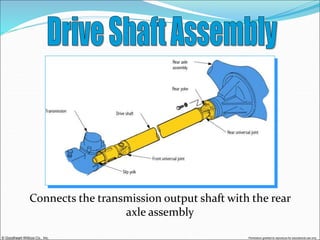
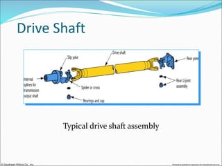
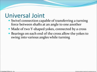
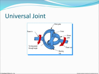
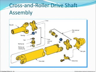
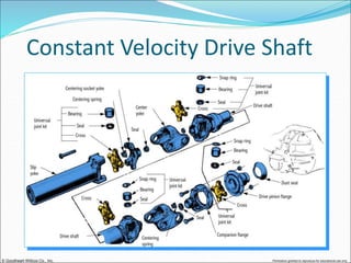
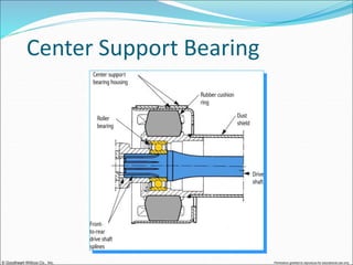
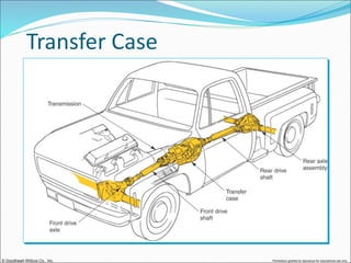
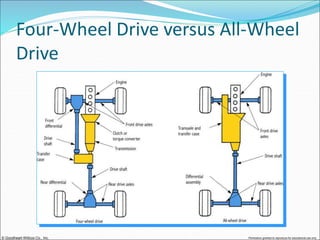
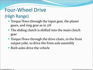
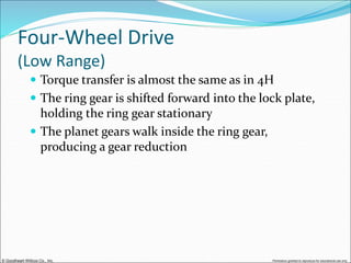
© Goodheart-Willcox Co., Inc. Permission granted to reproduce for educational use only
Connects the transmission output shaft with the rear
axle assembly
© Goodheart-Willcox Co., Inc. Permission granted to reproduce for educational use only
Components
 Slip yoke
 Front universal joint
 Drive shaft
 Rear universal joint
 Rear yoke
© Goodheart-Willcox Co., Inc. Permission granted to reproduce for educational use only
Functions
 Sends turning power from the transmission to the
rear axle assembly
 Flexes and allows vertical movement of the rear
axle assembly
 Provides a sliding action to adjust for changes in
driveline length
 Provides smooth power transfer
© Goodheart-Willcox Co., Inc. Permission granted to reproduce for educational use only
Operation
 The transmission output shaft turns the slip yoke
 The slip yoke turns the front universal joint,
driveshaft, rear universal joint, and rear yoke on the
differential
© Goodheart-Willcox Co., Inc. Permission granted to reproduce for educational use only
Driveline Flex
Universal joints let the driveline flex as the rear axle
moves up and down
© Goodheart-Willcox Co., Inc. Permission granted to reproduce for educational use only
Slip Yoke
 Splined to the transmission output shaft
 Allows for changes in driveline length by sliding in
and out of the transmission
 The outer diameter is machined smooth, providing
a bearing surface for the bushing and oil seal in the
transmission
© Goodheart-Willcox Co., Inc. Permission granted to reproduce for educational use only
Slip Yoke
© Goodheart-Willcox Co., Inc. Permission granted to reproduce for educational use only
Drive Shaft
 Hollow steel tube with permanent yokes welded on
each end
 Very strong and light
 Lightweight units may be made of thin-wall
aluminum with longitudinally aligned graphite
fibers for added strength
 May be single-piece, or two-piece
© Goodheart-Willcox Co., Inc. Permission granted to reproduce for educational use only
Drive Shaft
Typical drive shaft assembly
© Goodheart-Willcox Co., Inc. Permission granted to reproduce for educational use only
Drive Shaft Balance
 In high gears, the drive shaft turns at the same
speed as the engine
 The shaft must be accurately balanced
 The shaft is rotated on a balancing machine at the
factory
 Steel balancing weights are welded to the shaft to
reduce vibration
© Goodheart-Willcox Co., Inc. Permission granted to reproduce for educational use only
Drive Shaft Balancing Weights
© Goodheart-Willcox Co., Inc. Permission granted to reproduce for educational use only
Vibration Damper
 The drive shaft may be equipped with a large, ring-
shaped weight mounted on rubber
 Helps keep the shaft turning smoothly by
absorbing torsional vibration
© Goodheart-Willcox Co., Inc. Permission granted to reproduce for educational use only
Universal Joint
 Swivel connection capable of transferring a turning
force between shafts at an angle to one another
 Made of two Y-shaped yokes, connected by a cross
 Bearings on each end of the cross allow the yokes to
swing into various angles while turning
© Goodheart-Willcox Co., Inc. Permission granted to reproduce for educational use only
Universal Joint
© Goodheart-Willcox Co., Inc. Permission granted to reproduce for educational use only
Types of Universal Joints
© Goodheart-Willcox Co., Inc. Permission granted to reproduce for educational use only
Cross-and-Roller
© Goodheart-Willcox Co., Inc. Permission granted to reproduce for educational use only
Cross-and-Roller
 Cardan universal joint
 Most common type of joint
 The bearing caps are held stationary in the drive
shaft yoke
 The roller bearings reduce friction
 The cross is free to rotate inside the caps and yokes
© Goodheart-Willcox Co., Inc. Permission granted to reproduce for educational use only
Bearing Cap Retention
Several methods are used to retain the bearing cap in
the yoke
© Goodheart-Willcox Co., Inc. Permission granted to reproduce for educational use only
Cross-and-Roller Drive Shaft
Assembly
© Goodheart-Willcox Co., Inc. Permission granted to reproduce for educational use only
Constant Velocity Joint
 A cross-and-roller joint tends to accelerate and
decelerate during each revolution, setting up
torsional vibrations
 A constant velocity joint has two cross-and-roller
joints connected by a centering socket and center
yoke
 By using two joints, the output shaft speed
fluctuations are counteracted
© Goodheart-Willcox Co., Inc. Permission granted to reproduce for educational use only
Constant Velocity Joint
Speed changes at the output of the first joint are
offset by speed changes
at the other joint
© Goodheart-Willcox Co., Inc. Permission granted to reproduce for educational use only
Constant Velocity Drive Shaft
© Goodheart-Willcox Co., Inc. Permission granted to reproduce for educational use only
Ball-and-Trunnion Joint
 Constant velocity design
 Eliminates shaft speed fluctuations
 Allows for slight length changes in the driveline
© Goodheart-Willcox Co., Inc. Permission granted to reproduce for educational use only
Center Support Bearing
 Holds the middle of a two-piece drive shaft
 Bolts to the vehicle’s frame or body
 Common on pickup trucks and large vehicles with
long wheel bases
 The rubber mount prevents noise and vibration
from transferring into the passenger compartment
© Goodheart-Willcox Co., Inc. Permission granted to reproduce for educational use only
Center Support Bearing
© Goodheart-Willcox Co., Inc. Permission granted to reproduce for educational use only
Center Support Bearing
© Goodheart-Willcox Co., Inc. Permission granted to reproduce for educational use only
Two main types—Hotchkiss
driveline and torque
tube driveline
© Goodheart-Willcox Co., Inc. Permission granted to reproduce for educational use only
Hotchkiss Driveline
 An exposed drive shaft operates a rear axle
assembly mounted on springs
 Most common type of driveline
 Universal joints are used at both ends of the drive
shaft
 Cross-and-roller universal joints are most
commonly used
© Goodheart-Willcox Co., Inc. Permission granted to reproduce for educational use only
Torque Tube Driveline
 Uses a solid steel drive shaft enclosed in a large
hollow tube
 Only one swivel joint is used at the front
 The rear of the torque tube is a rigid part of the rear
axle housing
© Goodheart-Willcox Co., Inc. Permission granted to reproduce for educational use only
 Used to send power to both the front and rear axle
assemblies in a four-wheel-drive vehicle
 Mounted behind, and driven by, the transmission
 Two drive shafts run from the transfer case, one to each
drive axle
© Goodheart-Willcox Co., Inc. Permission granted to reproduce for educational use only
Transfer Case
© Goodheart-Willcox Co., Inc. Permission granted to reproduce for educational use only
Four-Wheel Drive versus All-Wheel
Drive
 Four-wheel drive has a transfer case separate from
the transmission
 drive ranges such as 2H, 4H, and 4L are provided
 All-wheel drive has the transfer case included as
part of the transaxle
© Goodheart-Willcox Co., Inc. Permission granted to reproduce for educational use only
Four-Wheel Drive versus All-Wheel
Drive
© Goodheart-Willcox Co., Inc. Permission granted to reproduce for educational use only
Transfer Case Construction
 Constructed much like a manual transmission
 uses shift forks, splines, gears, shims, and bearings
 Made of cast iron or aluminum
 Filled with lubricant (oil) that cuts friction
© Goodheart-Willcox Co., Inc. Permission granted to reproduce for educational use only
Transfer Case Construction
© Goodheart-Willcox Co., Inc. Permission granted to reproduce for educational use only
Transfer Case Ranges
 Two-wheel drive, high range (2H)
 normally provides a gear ratio of 1:1
 Four-wheel drive, high range (4H)
 normally provides a gear ratio of 1:1
 Four-wheel drive, low range (4L)
 normally provides a gear ratio of approximately 2:1
© Goodheart-Willcox Co., Inc. Permission granted to reproduce for educational use only
Power Flow
© Goodheart-Willcox Co., Inc. Permission granted to reproduce for educational use only
Two-Wheel Drive
(High Range)
 Provided for normal driving when four-wheel drive
is not needed
 Torque flows from the input gear to the locked
planet gears and ring gear, which rotate as a single
unit
 Torque is transferred to the main shaft through the
planet carrier
 Power flows out the rear yoke
© Goodheart-Willcox Co., Inc. Permission granted to reproduce for educational use only
Four-Wheel Drive
(High Range)
 Torque flows through the input gear, the planet
gears, and ring gear as in 2H
 The sliding clutch is shifted into the main clutch
gear
 Torque flows through the drive chain, to the front
output yoke, to drive the front axle assembly
 Both axles drive the vehicle
© Goodheart-Willcox Co., Inc. Permission granted to reproduce for educational use only
Four-Wheel Drive
(Low Range)
 Torque transfer is almost the same as in 4H
 The ring gear is shifted forward into the lock plate,
holding the ring gear stationary
 The planet gears walk inside the ring gear,
producing a gear reduction
© Goodheart-Willcox Co., Inc. Permission granted to reproduce for educational use only
All-Wheel Drive
 Does not use a conventional transfer case
 Designed for a front-wheel-drive transaxle or a
transmission
 The transmission or transaxle is modified to allow
power flow to the front and rear drive axles
© Goodheart-Willcox Co., Inc. Permission granted to reproduce for educational use only
All-Wheel Drive
A fluid coupling controls the power split to the front
and rear axle assemblies

Drive shaft.ppt

  • 1.
    © Goodheart-Willcox Co.,Inc. Permission granted to reproduce for educational use only
  • 2.
    © Goodheart-Willcox Co.,Inc. Permission granted to reproduce for educational use only Connects the transmission output shaft with the rear axle assembly
  • 3.
    © Goodheart-Willcox Co.,Inc. Permission granted to reproduce for educational use only Components  Slip yoke  Front universal joint  Drive shaft  Rear universal joint  Rear yoke
  • 4.
    © Goodheart-Willcox Co.,Inc. Permission granted to reproduce for educational use only Functions  Sends turning power from the transmission to the rear axle assembly  Flexes and allows vertical movement of the rear axle assembly  Provides a sliding action to adjust for changes in driveline length  Provides smooth power transfer
  • 5.
    © Goodheart-Willcox Co.,Inc. Permission granted to reproduce for educational use only Operation  The transmission output shaft turns the slip yoke  The slip yoke turns the front universal joint, driveshaft, rear universal joint, and rear yoke on the differential
  • 6.
    © Goodheart-Willcox Co.,Inc. Permission granted to reproduce for educational use only Driveline Flex Universal joints let the driveline flex as the rear axle moves up and down
  • 7.
    © Goodheart-Willcox Co.,Inc. Permission granted to reproduce for educational use only Slip Yoke  Splined to the transmission output shaft  Allows for changes in driveline length by sliding in and out of the transmission  The outer diameter is machined smooth, providing a bearing surface for the bushing and oil seal in the transmission
  • 8.
    © Goodheart-Willcox Co.,Inc. Permission granted to reproduce for educational use only Slip Yoke
  • 9.
    © Goodheart-Willcox Co.,Inc. Permission granted to reproduce for educational use only Drive Shaft  Hollow steel tube with permanent yokes welded on each end  Very strong and light  Lightweight units may be made of thin-wall aluminum with longitudinally aligned graphite fibers for added strength  May be single-piece, or two-piece
  • 10.
    © Goodheart-Willcox Co.,Inc. Permission granted to reproduce for educational use only Drive Shaft Typical drive shaft assembly
  • 11.
    © Goodheart-Willcox Co.,Inc. Permission granted to reproduce for educational use only Drive Shaft Balance  In high gears, the drive shaft turns at the same speed as the engine  The shaft must be accurately balanced  The shaft is rotated on a balancing machine at the factory  Steel balancing weights are welded to the shaft to reduce vibration
  • 12.
    © Goodheart-Willcox Co.,Inc. Permission granted to reproduce for educational use only Drive Shaft Balancing Weights
  • 13.
    © Goodheart-Willcox Co.,Inc. Permission granted to reproduce for educational use only Vibration Damper  The drive shaft may be equipped with a large, ring- shaped weight mounted on rubber  Helps keep the shaft turning smoothly by absorbing torsional vibration
  • 14.
    © Goodheart-Willcox Co.,Inc. Permission granted to reproduce for educational use only Universal Joint  Swivel connection capable of transferring a turning force between shafts at an angle to one another  Made of two Y-shaped yokes, connected by a cross  Bearings on each end of the cross allow the yokes to swing into various angles while turning
  • 15.
    © Goodheart-Willcox Co.,Inc. Permission granted to reproduce for educational use only Universal Joint
  • 16.
    © Goodheart-Willcox Co.,Inc. Permission granted to reproduce for educational use only Types of Universal Joints
  • 17.
    © Goodheart-Willcox Co.,Inc. Permission granted to reproduce for educational use only Cross-and-Roller
  • 18.
    © Goodheart-Willcox Co.,Inc. Permission granted to reproduce for educational use only Cross-and-Roller  Cardan universal joint  Most common type of joint  The bearing caps are held stationary in the drive shaft yoke  The roller bearings reduce friction  The cross is free to rotate inside the caps and yokes
  • 19.
    © Goodheart-Willcox Co.,Inc. Permission granted to reproduce for educational use only Bearing Cap Retention Several methods are used to retain the bearing cap in the yoke
  • 20.
    © Goodheart-Willcox Co.,Inc. Permission granted to reproduce for educational use only Cross-and-Roller Drive Shaft Assembly
  • 21.
    © Goodheart-Willcox Co.,Inc. Permission granted to reproduce for educational use only Constant Velocity Joint  A cross-and-roller joint tends to accelerate and decelerate during each revolution, setting up torsional vibrations  A constant velocity joint has two cross-and-roller joints connected by a centering socket and center yoke  By using two joints, the output shaft speed fluctuations are counteracted
  • 22.
    © Goodheart-Willcox Co.,Inc. Permission granted to reproduce for educational use only Constant Velocity Joint Speed changes at the output of the first joint are offset by speed changes at the other joint
  • 23.
    © Goodheart-Willcox Co.,Inc. Permission granted to reproduce for educational use only Constant Velocity Drive Shaft
  • 24.
    © Goodheart-Willcox Co.,Inc. Permission granted to reproduce for educational use only Ball-and-Trunnion Joint  Constant velocity design  Eliminates shaft speed fluctuations  Allows for slight length changes in the driveline
  • 25.
    © Goodheart-Willcox Co.,Inc. Permission granted to reproduce for educational use only Center Support Bearing  Holds the middle of a two-piece drive shaft  Bolts to the vehicle’s frame or body  Common on pickup trucks and large vehicles with long wheel bases  The rubber mount prevents noise and vibration from transferring into the passenger compartment
  • 26.
    © Goodheart-Willcox Co.,Inc. Permission granted to reproduce for educational use only Center Support Bearing
  • 27.
    © Goodheart-Willcox Co.,Inc. Permission granted to reproduce for educational use only Center Support Bearing
  • 28.
    © Goodheart-Willcox Co.,Inc. Permission granted to reproduce for educational use only Two main types—Hotchkiss driveline and torque tube driveline
  • 29.
    © Goodheart-Willcox Co.,Inc. Permission granted to reproduce for educational use only Hotchkiss Driveline  An exposed drive shaft operates a rear axle assembly mounted on springs  Most common type of driveline  Universal joints are used at both ends of the drive shaft  Cross-and-roller universal joints are most commonly used
  • 30.
    © Goodheart-Willcox Co.,Inc. Permission granted to reproduce for educational use only Torque Tube Driveline  Uses a solid steel drive shaft enclosed in a large hollow tube  Only one swivel joint is used at the front  The rear of the torque tube is a rigid part of the rear axle housing
  • 31.
    © Goodheart-Willcox Co.,Inc. Permission granted to reproduce for educational use only  Used to send power to both the front and rear axle assemblies in a four-wheel-drive vehicle  Mounted behind, and driven by, the transmission  Two drive shafts run from the transfer case, one to each drive axle
  • 32.
    © Goodheart-Willcox Co.,Inc. Permission granted to reproduce for educational use only Transfer Case
  • 33.
    © Goodheart-Willcox Co.,Inc. Permission granted to reproduce for educational use only Four-Wheel Drive versus All-Wheel Drive  Four-wheel drive has a transfer case separate from the transmission  drive ranges such as 2H, 4H, and 4L are provided  All-wheel drive has the transfer case included as part of the transaxle
  • 34.
    © Goodheart-Willcox Co.,Inc. Permission granted to reproduce for educational use only Four-Wheel Drive versus All-Wheel Drive
  • 35.
    © Goodheart-Willcox Co.,Inc. Permission granted to reproduce for educational use only Transfer Case Construction  Constructed much like a manual transmission  uses shift forks, splines, gears, shims, and bearings  Made of cast iron or aluminum  Filled with lubricant (oil) that cuts friction
  • 36.
    © Goodheart-Willcox Co.,Inc. Permission granted to reproduce for educational use only Transfer Case Construction
  • 37.
    © Goodheart-Willcox Co.,Inc. Permission granted to reproduce for educational use only Transfer Case Ranges  Two-wheel drive, high range (2H)  normally provides a gear ratio of 1:1  Four-wheel drive, high range (4H)  normally provides a gear ratio of 1:1  Four-wheel drive, low range (4L)  normally provides a gear ratio of approximately 2:1
  • 38.
    © Goodheart-Willcox Co.,Inc. Permission granted to reproduce for educational use only Power Flow
  • 39.
    © Goodheart-Willcox Co.,Inc. Permission granted to reproduce for educational use only Two-Wheel Drive (High Range)  Provided for normal driving when four-wheel drive is not needed  Torque flows from the input gear to the locked planet gears and ring gear, which rotate as a single unit  Torque is transferred to the main shaft through the planet carrier  Power flows out the rear yoke
  • 40.
    © Goodheart-Willcox Co.,Inc. Permission granted to reproduce for educational use only Four-Wheel Drive (High Range)  Torque flows through the input gear, the planet gears, and ring gear as in 2H  The sliding clutch is shifted into the main clutch gear  Torque flows through the drive chain, to the front output yoke, to drive the front axle assembly  Both axles drive the vehicle
  • 41.
    © Goodheart-Willcox Co.,Inc. Permission granted to reproduce for educational use only Four-Wheel Drive (Low Range)  Torque transfer is almost the same as in 4H  The ring gear is shifted forward into the lock plate, holding the ring gear stationary  The planet gears walk inside the ring gear, producing a gear reduction
  • 42.
    © Goodheart-Willcox Co.,Inc. Permission granted to reproduce for educational use only All-Wheel Drive  Does not use a conventional transfer case  Designed for a front-wheel-drive transaxle or a transmission  The transmission or transaxle is modified to allow power flow to the front and rear drive axles
  • 43.
    © Goodheart-Willcox Co.,Inc. Permission granted to reproduce for educational use only All-Wheel Drive A fluid coupling controls the power split to the front and rear axle assemblies