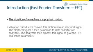
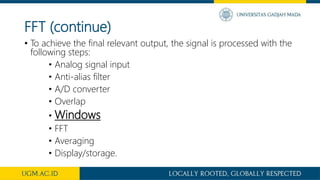
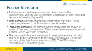
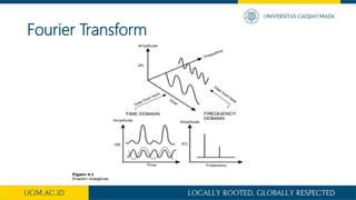
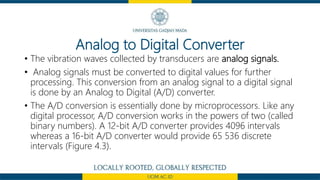
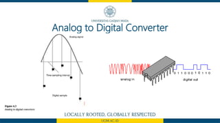
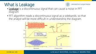
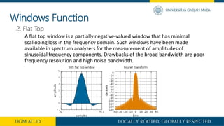
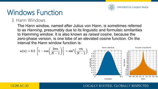
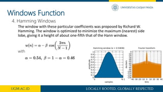
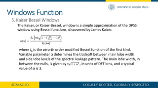
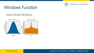
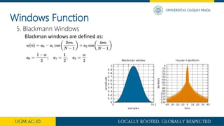
WINDOWING
Awal Rahandito (14/363281/TK/41439)
Fajar Fitrahadi Danda (14/363315/TK/41456)
Nyoman Arya Wiriyawan (14/363367/TK/41500)
Rama Gian Hendraloka (14/364411/TK/41967)
Introduction (Fast Fourier Transform – FFT)
• The vibration of a machine is a physical motion.
• Vibration transducers convert this motion into an electrical signal.
The electrical signal is then passed on to data collectors or
analyzers. The analyzers then process this signal to give the FFTs
and other parameters.
FFT (continue)
• To achieve the final relevant output, the signal is processed with the
following steps:
• Analog signal input
• Anti-alias filter
• A/D converter
• Overlap
• Windows
• FFT
• Averaging
• Display/storage.
Fourier Transform
• A vibration or a system response can be represented by
displacement, velocity and acceleration amplitudes in both time and
frequency domains (Figure 4.1).
• Time domain consists of amplitude that varies with time. This is
commonly referred to as filter-out or overall reading.
• Frequency domain is the domain where amplitudes are shown as
series of sine and cosine waves. These waves have a magnitude and
a phase, which vary with frequency.
• The measured vibrations are always in analog form (time domain),
and need to be transformed to the frequency domain. This is the
purpose of the fast Fourier transform (FFT). The FFT is thus a
calculation on a sampled signal.
Fourier Transform
Analog to Digital Converter
• The vibration waves collected by transducers are analog signals.
• Analog signals must be converted to digital values for further
processing. This conversion from an analog signal to a digital signal
is done by an Analog to Digital (A/D) converter.
• The A/D conversion is essentially done by microprocessors. Like any
digital processor, A/D conversion works in the powers of two (called
binary numbers). A 12-bit A/D converter provides 4096 intervals
whereas a 16-bit A/D converter would provide 65 536 discrete
intervals (Figure 4.3).
Analog to Digital Converter
WINDOW??
WINDOWING
• After the signal was digitized using an A/D converter, the next step in
the process (before it can be subjected to the FFT algorithm) is called
windowing
• Windowing is the equivalent of multiplying the signal
sample by a window function of the same length
• A ‘window’ must be applied to the data to minimize signal ‘leakage’
effects
The Principle of Windowing
What is Leakage
• Leakage is a discontinuous signal that can cause a noise in FFT
diagram
• FFT algorithm reads a discontinuous signal as a sidebands, so that
the analyst will be more difficult in understanding the diagram.
Windows Function
• There are many window functions. Some used in vibration signal
processing are:
1. Rectangular (basically no window)
2. Flat top
3. Hann
4. Hamming
5. Kaiser Bessel
6. Blackman
7. Barlett
Generally, only the first three window functions mentioned above are
available in most analyzers.
Windows Function
1. Rectangular
The rectangular window (sometimes known as the boxcar or Dirichlet window)
is the simplest window, equivalent to replacing all but N values of a data
sequence by zeros, making it appear as though the waveform suddenly turns on
and off:
Windows Function
2. Flat Top
A flat top window is a partially negative-valued window that has minimal
scalloping loss in the frequency domain. Such windows have been made
available in spectrum analyzers for the measurement of amplitudes of
sinusoidal frequency components. Drawbacks of the broad bandwidth are poor
frequency resolution and high noise bandwidth.
Windows Function
3. Hann Windows
The Hann window, named after Julius von Hann, is sometimes referred
to as Hanning, presumably due to its linguistic and formulaic similarities
to Hamming window. It is also known as raised cosine, because the
zero-phase version, is one lobe of an elevated cosine function. On the
interval the Hann window function is:
Windows Function
4. Hamming Windows
The window with these particular coefficients was proposed by Richard W.
Hamming. The window is optimized to minimize the maximum (nearest) side
lobe, giving it a height of about one-fifth that of the Hann window.
with
Windows Function
5. Kaiser Bessel Windows
The Kaiser, or Kaiser-Bessel, window is a simple approximation of the DPSS
window using Bessel functions, discovered by James Kaiser.
where I0 is the zero-th order modified Bessel function of the first kind.
Variable parameter α determines the tradeoff between main lobe width
and side lobe levels of the spectral leakage pattern. The main lobe width, in
between the nulls, is given by , in units of DFT bins, and a typical
value of α is 3.
Windows Function
Kaiser Bessel Windows
Windows Function
5. Blackmann Windows
Blackman windows are defined as:
Windows Function
5. Barlett Windows
Barlett or Triangular Windows defined as:
THANK YOU

Windowing (signal processing)

  • 1.
    WINDOWING Awal Rahandito (14/363281/TK/41439) FajarFitrahadi Danda (14/363315/TK/41456) Nyoman Arya Wiriyawan (14/363367/TK/41500) Rama Gian Hendraloka (14/364411/TK/41967)
  • 2.
    Introduction (Fast FourierTransform – FFT) • The vibration of a machine is a physical motion. • Vibration transducers convert this motion into an electrical signal. The electrical signal is then passed on to data collectors or analyzers. The analyzers then process this signal to give the FFTs and other parameters.
  • 3.
    FFT (continue) • Toachieve the final relevant output, the signal is processed with the following steps: • Analog signal input • Anti-alias filter • A/D converter • Overlap • Windows • FFT • Averaging • Display/storage.
  • 4.
    Fourier Transform • Avibration or a system response can be represented by displacement, velocity and acceleration amplitudes in both time and frequency domains (Figure 4.1). • Time domain consists of amplitude that varies with time. This is commonly referred to as filter-out or overall reading. • Frequency domain is the domain where amplitudes are shown as series of sine and cosine waves. These waves have a magnitude and a phase, which vary with frequency. • The measured vibrations are always in analog form (time domain), and need to be transformed to the frequency domain. This is the purpose of the fast Fourier transform (FFT). The FFT is thus a calculation on a sampled signal.
  • 5.
  • 6.
    Analog to DigitalConverter • The vibration waves collected by transducers are analog signals. • Analog signals must be converted to digital values for further processing. This conversion from an analog signal to a digital signal is done by an Analog to Digital (A/D) converter. • The A/D conversion is essentially done by microprocessors. Like any digital processor, A/D conversion works in the powers of two (called binary numbers). A 12-bit A/D converter provides 4096 intervals whereas a 16-bit A/D converter would provide 65 536 discrete intervals (Figure 4.3).
  • 7.
  • 8.
  • 9.
    WINDOWING • After thesignal was digitized using an A/D converter, the next step in the process (before it can be subjected to the FFT algorithm) is called windowing • Windowing is the equivalent of multiplying the signal sample by a window function of the same length • A ‘window’ must be applied to the data to minimize signal ‘leakage’ effects
  • 10.
  • 11.
    What is Leakage •Leakage is a discontinuous signal that can cause a noise in FFT diagram • FFT algorithm reads a discontinuous signal as a sidebands, so that the analyst will be more difficult in understanding the diagram.
  • 12.
    Windows Function • Thereare many window functions. Some used in vibration signal processing are: 1. Rectangular (basically no window) 2. Flat top 3. Hann 4. Hamming 5. Kaiser Bessel 6. Blackman 7. Barlett Generally, only the first three window functions mentioned above are available in most analyzers.
  • 13.
    Windows Function 1. Rectangular Therectangular window (sometimes known as the boxcar or Dirichlet window) is the simplest window, equivalent to replacing all but N values of a data sequence by zeros, making it appear as though the waveform suddenly turns on and off:
  • 14.
    Windows Function 2. FlatTop A flat top window is a partially negative-valued window that has minimal scalloping loss in the frequency domain. Such windows have been made available in spectrum analyzers for the measurement of amplitudes of sinusoidal frequency components. Drawbacks of the broad bandwidth are poor frequency resolution and high noise bandwidth.
  • 15.
    Windows Function 3. HannWindows The Hann window, named after Julius von Hann, is sometimes referred to as Hanning, presumably due to its linguistic and formulaic similarities to Hamming window. It is also known as raised cosine, because the zero-phase version, is one lobe of an elevated cosine function. On the interval the Hann window function is:
  • 16.
    Windows Function 4. HammingWindows The window with these particular coefficients was proposed by Richard W. Hamming. The window is optimized to minimize the maximum (nearest) side lobe, giving it a height of about one-fifth that of the Hann window. with
  • 17.
    Windows Function 5. KaiserBessel Windows The Kaiser, or Kaiser-Bessel, window is a simple approximation of the DPSS window using Bessel functions, discovered by James Kaiser. where I0 is the zero-th order modified Bessel function of the first kind. Variable parameter α determines the tradeoff between main lobe width and side lobe levels of the spectral leakage pattern. The main lobe width, in between the nulls, is given by , in units of DFT bins, and a typical value of α is 3.
  • 18.
  • 19.
    Windows Function 5. BlackmannWindows Blackman windows are defined as:
  • 20.
    Windows Function 5. BarlettWindows Barlett or Triangular Windows defined as:
  • 21.