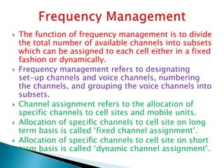
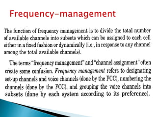
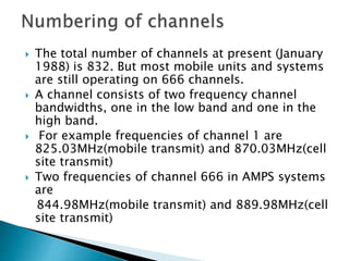
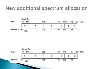
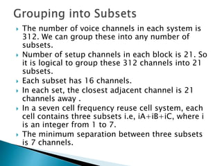
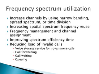
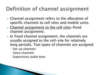
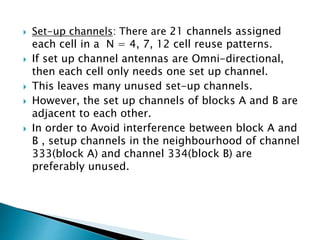
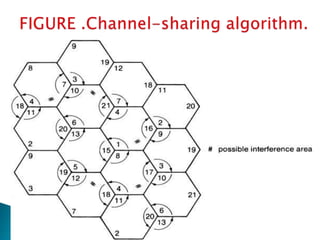
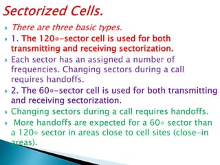
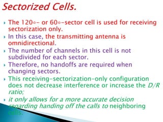
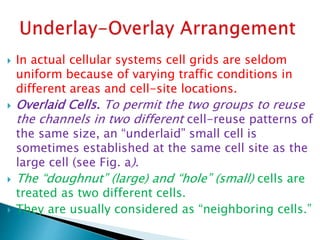
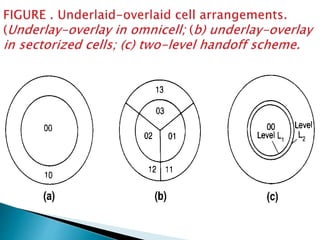
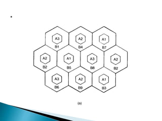
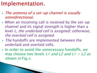
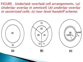
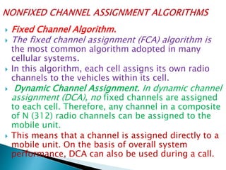
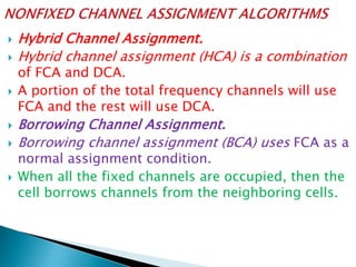
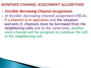
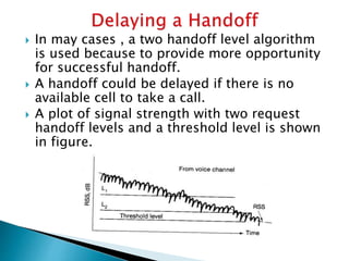
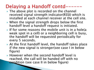
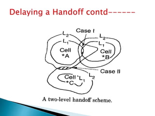
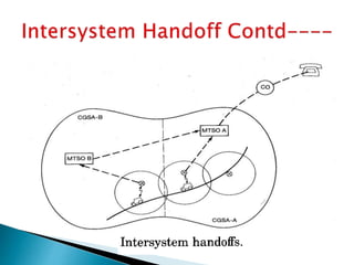
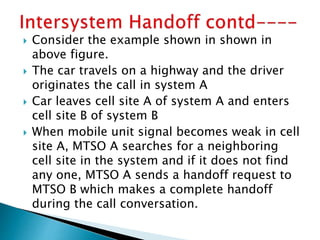
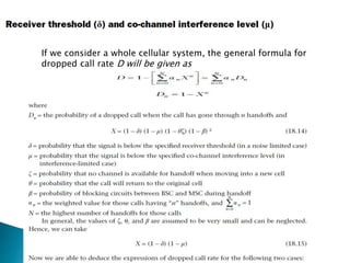
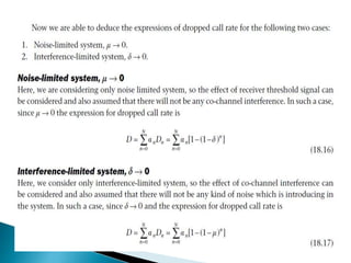
This document discusses frequency management and channel assignment in cellular networks. It explains that frequency management divides available channels into subsets that can be assigned to each cell, either fixed or dynamically. It describes how channels are divided and grouped in the Advanced Mobile Phone System (AMPS). Channels can be assigned to cell sites on a long-term fixed basis or short-term dynamic basis. The document also discusses set-up channels, voice channels, frequency reuse patterns, and techniques for channel sharing, borrowing, and sectorization to improve spectrum efficiency and traffic capacity.
The document discusses GSM (Global System for Mobile Communication), including its definition as a 2G cellular standard, system architecture with components like the mobile station, base station subsystem, and network subsystem, basic features like call waiting and advanced features like roaming, future developments like UMTS, and advantages like international roaming capabilities and efficient use of spectrum.
Cordless phones allow wireless communication between a portable handset and a base station connected to a telephone line. There are different generations of cordless phone technology, from early analog systems to newer digital standards like DECT and PHS. DECT is widely used in Europe and other parts of the world for home and office cordless phone systems, offering better voice quality and security than analog predecessors. Digital systems also provide features like extended battery life and range compared to early cordless phones.
Cellular networks divide geographic areas into cells served by low-power base stations to reuse frequencies. Adjacent cells are assigned different frequencies to avoid interference. As capacity demands increase, networks employ techniques like frequency borrowing, cell splitting, cell sectoring, and microcells. Cellular standards like GSM use TDMA to allow multiple users per cell by dividing the air interface into time slots. CDMA spreads user data over a wide bandwidth using unique codes and allows soft handoff between cells. Third generation networks support high-speed data and multimedia services.
Cellular communication systems have evolved through multiple generations from analog 1G to digital 4G systems. A cellular network is divided into geographical areas called cells served by base transceiver stations. Cells are grouped into clusters where frequencies are reused to allow for more subscribers. When making a call, the cellular phone registers with the local base station which routes the call through switching centers to establish communication with the intended recipient. Modern cellular networks support additional services beyond voice like texting, internet access, and location tracking through technologies like GSM that employ protocols like TDMA for efficient frequency usage.
This document discusses key concepts in cellular networks including frequency reuse, channel assignment strategies, interference reduction techniques, and methods for improving capacity. It introduces frequency reuse where the same channels are used in different cells separated by sufficient distance. Channel assignment strategies include fixed and dynamic assignment. Sources of interference like co-channel and adjacent channel are described along with methods to calculate signal-to-interference ratio. Improving capacity is discussed through cell splitting and sectoring.
Today's cellular telephone systems operate by dividing geographic areas into cells served by base stations. Each cell is assigned certain radio frequencies that are reused in non-neighboring cells to increase coverage and capacity. When a mobile user moves between cells, the call is handed off from one base station to another through a mobile switching center to avoid disconnection. Modern cellular networks use digital technologies like CDMA, TDMA and FDMA to provide voice, text, and data services to users through cellular infrastructure.
The document discusses the cellular concept in wireless networks. Key points include:
- Cells have a hexagonal shape and neighboring cells reuse frequencies to avoid interference and increase capacity.
- Frequency reuse allows more simultaneous calls by allocating the same set of frequencies to different neighboring cells.
- Cell size is a tradeoff between interference and system capacity - smaller cells mean lower power needs but more cells and handoffs.
CDMA is a digital cellular standard that allows multiple users to access the same radio frequency channel simultaneously through the use of unique code sequences. Users are separated by spreading their transmitted signals across the frequency band using pseudo-random codes. CDMA provides advantages over other multiple access techniques like FDMA and TDMA such as increased capacity, soft handoffs between cells, and covert operation due to its noise-like signals. The IS-95 standard introduced CDMA to cellular networks and specified the use of orthogonal codes to separate signals and a 1.25 MHz channel bandwidth to support multiple simultaneous voice calls.
Cellular mobile communication uses multiple access methods like TDMA, FDMA, and CDMA to allow many users to access the network simultaneously over a limited wireless spectrum. It works by dividing geographic areas into cells served by base transceiver stations and switching centers, with cellular phones communicating with the nearest base station. When users move between cells, their communication is handed off seamlessly to the new base station through the switching network to maintain the connection.
The document describes the key components and architecture of the GSM system. It discusses the objectives of GSM including supporting international roaming and good speech quality. It then describes the hierarchy of the GSM system including the mobile station, radio subsystem with base stations and base station controllers, and the network and switching subsystem with mobile switching centers and databases. It also discusses the air interface including frequency allocation and channel structure.
This document discusses modulation formats including minimum shift keying (MSK) and Gaussian MSK. It provides details on MSK such as it having a modulation index of 0.5, which makes the signals orthogonal and easier to separate at the receiver. MSK provides benefits like constant envelope, good spectral efficiency, and better bit error rate performance compared to frequency shift keying. The document also contains equations for MSK, diagrams of MSK transmission and reception, and information on the power spectral density of MSK and how it compares to Gaussian MSK.
Cellular networks employ frequency reuse to increase capacity by assigning different frequency channels to adjacent cells to avoid interference. Due to co-channel interference, the same frequency cannot be used in adjacent cells and frequencies assigned to different cells must be separated by distances large enough to keep interference levels low. The objective of frequency reuse is to reuse frequencies in nearby cells by assigning different frequencies to adjacent cells using a frequency reuse plan and cluster size.
The document summarizes the history and technical standards of GSM cellular networks. It describes how GSM networks are structured hierarchically with mobile switching centers, location areas, and base station controllers. It also explains the key identifiers used in GSM including the IMSI, IMEI, MSISDN, and MSRN. The document concludes by covering the frequency division multiple access and time division multiple access techniques used in GSM as well as some inefficiencies in the standard.
This document discusses the history and principles of communications systems. It covers the stages of communications development from early electrical engineering foundations to modern integrated digital networks. Key topics include automated telephone switching, radio transmission, data transfer rates using parallel and serial communications, Boolean logic operations, bit shifting and masking, and matrix operations for multiple data formats in telecommunications.
This document provides an overview of wireless and mobile network architectures, including personal communication services (PCS). It discusses several cellular and cordless systems such as AMPS, GSM, IS-136, IS-95, DECT, PHS, and PACS. These systems use different multiple access techniques and spectrum to provide voice and data services connected to the public switched telephone network. The document also introduces third generation wireless systems that aim to support higher speeds and multimedia services.
AMPS was the first-generation analog cellular system developed in the 1970s and 1980s. It used analog FM modulation with 30 kHz channel bandwidths. AMPS was deployed across North America in the early 1980s and introduced cellular communications. However, it had limitations like low capacity and lack of privacy. Successor 2G digital standards like NAMPS and D-AMPS improved capacity but have now been replaced by newer 3G and 4G technologies.
This document discusses frequency reuse in cellular networks. It describes the frequency bands used in GSM900 and GSM1800 standards. Common frequency reuse patterns include "4 3", "3 3", and dual frequency reuse. Frequency reuse allows the same frequencies to be used in different cells by ensuring sufficient distance between those cells. The document also provides equations to calculate frequency reuse distance based on cell radius and reuse factor.
There are 3 main propagation mechanisms in mobile communication systems:
1. Reflection occurs when signals bounce off surfaces like buildings and earth.
2. Diffraction is when signals bend around obstacles like hills and buildings.
3. Scattering is when signals are deflected in many directions by small obstacles like trees and signs. These 3 mechanisms impact the received power and must be considered in propagation models.
Concepts of & cell sectoring and micro cellKundan Kumar
The document discusses concepts related to cellular network sectoring and microcells. It explains that cells can have square or hexagonal shapes, with hexagons providing equidistant antennas. Frequency reuse allows the same frequencies to be used in different cells by controlling base station power to limit interference. Common frequency reuse patterns include reuse factors of 1, 3, 7, etc. Capacity can be increased through methods like frequency borrowing, cell splitting, cell sectoring, and microcells which use smaller cell sizes.
The document provides an overview of the public switched telephone network (PSTN). It discusses that the PSTN is the interconnected telephone system that uses copper wires to make circuit-switched calls. It then covers the evolution of the PSTN from its invention in 1876 to present digital switches, the use of bandwidth allocation and numbering schemes, and call setup which involves signaling and switching systems to route calls.
CDMA is a digital cellular technology that allows multiple users to access a single radio channel simultaneously through the use of unique code assignments. The document discusses CDMA network architecture, which includes mobile stations, base stations, base station controllers, mobile switching centers, home and visitor location registers, and authentication centers. It also compares CDMA to earlier multiple access technologies like TDMA and FDMA, noting advantages of CDMA like increased capacity and soft handoffs between cells using the same frequency.
The document provides information on the evolution of wireless networks from 1G to 3G. It discusses the key components and architecture of cellular systems including base stations, mobile switching centers and their connection to the public switched telephone network. It also compares the differences between wireless and wired networks, and describes some of the limitations of early wireless networking. Finally, it covers topics like traffic routing, circuit switching, packet switching and the X.25 protocol.
This document discusses the differences between directional and omnidirectional antennas and when each type may be preferable. It begins by defining omnidirectional antennas as having equal reception/transmission in all directions, shown as a circular pattern. Directional antennas focus RF energy in specific directions through gain and directivity, shown through bidirectional and unidirectional patterns. The key factor is signal-to-noise ratio - directional antennas can increase the desired signal and decrease unwanted noise by positioning lobes and nulls. The best solution may be using multiple antenna types and a switch to select the optimal pattern for different situations.
The document discusses different channel assignment strategies for wireless networks, including fixed channel assignment where each cell is predetermined channels and dynamic channel assignment where channels are allocated on request based on factors like channel occupancy. It also describes a partially overlapping channel (FPOC) assignment strategy that aims to increase capacity while minimizing interference through intelligent channel allocation between neighboring nodes.
2.6 cellular concepts - frequency reusing, channel assignmentJAIGANESH SEKAR
- Cellular networks address the problem of limited spectrum availability by using frequency reuse, where nearby base stations are assigned different channels to avoid interference. Cells are arranged in a hexagonal pattern and the same set of channels are reused in cells sufficiently far from each other.
- There are two main channel assignment strategies - fixed assignment, where each cell has a predetermined set of channels, and dynamic assignment, where channels are allocated on demand by a central controller considering interference levels. Dynamic assignment helps improve spectrum utilization but requires more complex coordination.
- Frequency reuse allows the available spectrum to be reused as needed across multiple cells as long as interference is kept at acceptable levels, increasing network capacity.
This document discusses telecommunication switching systems. It covers several topics:
1) It describes three types of switching systems - circuit switching, message switching, and packet switching. Circuit and message switching are used in telecommunication, while packet switching is used for computer networks.
2) It also discusses different classes of switching systems based on how information is divided, including space, time, and frequency division switches.
3) A key part is stored program control (SPC) exchanges, which use computers and software to control call switching. SPC enables many features and more flexibility. Exchanges can use centralized or distributed SPC architectures.
This document provides an overview of cellular networks. It discusses key concepts like cells, base stations, frequency reuse, and multiple access methods. It describes how location of mobile devices is managed through location updating and paging. It also covers handoff which allows active calls to continue seamlessly as users move between different cells.
Wireless communication technologies have evolved from Guglielmo Marconi's early radio demonstrations in 1897. In the 1960s-1970s, Bell Laboratories developed the cellular concept, which enabled wireless communication networks to serve entire populations. This led to the development of cellular mobile systems using radio frequency technology. Cellular systems use a hexagonal cell structure and frequency reuse to improve spectrum efficiency and service capacity. They employ technologies such as handoff, dynamic channel assignment, and prioritization of handoffs to manage calls as users move between cells.
Frequencies management,Channel assignments,
Frequency reuse, System capacity and its improvement: Cell spliting and sectoring, Handoffs & its types, prioritizing handoff, Umbrella cell approach, Cell dragging, Roaming, Co channel and adjacent channel interference, Improving coverage- Repeaters for range extension and microcell zone concept, Examples
1) Frequency management divides available channels into subsets which can be assigned to each cell site either fixedly or dynamically. Channel assignment allocates specific channels to cell sites and mobile units.
2) Channels are numbered and divided into groups, with 666 total channels divided into blocks A and B of 333 channels each. Channels are further divided into voice channels and setup channels.
3) Setup channels are used to setup calls and are assigned one per sector, with 21 sectors requiring 21 setup channels. They are used for both mobile-originating and land-originating calls.
05. Frequency Management and Channel Assignment.pdfsamiulsuman
This document discusses frequency management and channel assignment in cellular networks. It covers:
- Frequency management which includes designating setup and voice channels, numbering channels, and grouping voice channels into subsets.
- Channel assignment which allocates specific channels to cell sites on a long-term basis and mobile units on a short-term basis during calls.
- The original 666 channels were divided into blocks A and B, with setup channels in specific ranges and voice channels assigned to each block. Additional spectrum has since been added up to channel 1023.
Wireless cellular networks divide geographic areas into cells served by base stations to allow for frequency reuse. As users travel between cells, their calls are handed off seamlessly. Cellular systems improve capacity by allocating unique frequency groups to each cell and reusing the same frequencies in cells sufficiently distant from each other. Larger networks connect multiple base stations and mobile switching centers to facilitate roaming and complete calls between mobile and fixed users.
Gives you the complete knowledge of different channel allocation techniques, reverse and forward CDMA, GSM Frame Structure, GSM channel Types, cellular concepts, handoff strategies, Frequency reuse and GSM call structure.
This PDF provides a in-depth explanation for all the concepts and practices used before.
The cellular concept solves spectral congestion issues by reusing radio channels in different hexagonal cells. Hexagonal cells provide full coverage with minimal cells and equal distance between cell centers. Each cell is assigned a group of channels to limit interference between neighboring cells using frequency planning. The capacity of the system increases with the number of times the frequency plan can be reused across different cell clusters.
Cellular systems use multiple low-power transmitters (base stations) rather than a single, high-power transmitter to increase capacity and coverage. Frequency reuse is used to allocate channels to nearby base stations to minimize interference. Handoff strategies are employed to transfer calls between base stations as users move. Interference and power control techniques aim to equalize signal power levels and improve capacity. Traffic engineering principles including Erlang formulas are applied to determine the optimal number of channels needed based on expected call volumes.
cellular concepts in wireless communicationasadkhan1327
The document discusses the concept of frequency reuse in cellular networks. It explains that a limited radio spectrum is used to serve millions of subscribers by dividing the network coverage area into cells and reusing frequencies across spatially separated cells. Each cell is allocated a portion of the total available frequencies, and neighboring cells are assigned different frequencies to minimize interference. The frequency reuse factor is defined as the ratio of the minimum distance between co-channel cells to the cell radius. Larger frequency reuse factors provide better isolation between co-channel cells but reduce network capacity. The document also covers additional topics like different channel assignment strategies, handoff methods, interference calculation and optimization of frequency reuse networks.
This presentation contains the basic of cellular system.
in which direction the cellular system works and how it changes the network from one bast station to another is simply explained.
how Hand-off occur between two base station is shown via figure to understand well.
the cell system in mobile network and the cell spliting, sectoring, microcell zone concept is also explained well.
Please take a look.
may be it is helpfull for you.
Thank you.
The document provides an overview of fundamental concepts in cellular engineering. It discusses the goals of cellular systems to have high capacity and large coverage area through efficient use of limited spectrum. Key concepts explained include frequency reuse, where the same radio channels are reused in different cells to serve more users; channel assignment strategies like fixed and dynamic allocation; and techniques to enhance capacity like cell splitting, sectoring, and microcell zones. The handoff process is also summarized, which allows seamless transfer of calls between base stations as users move between cells.
This document discusses the concept of cellular communications and frequency reuse. It describes how early mobile phone systems used high-powered transmitters with large coverage areas and low capacity. Cellular systems divide the coverage area into smaller cells served by low-power transmitters to reuse frequencies and increase capacity. Cells are arranged in a hexagonal layout and frequencies are reused in clusters of cells separated by a reuse distance to avoid interference. The cluster size determines the system's capacity and interference levels.
The cellular concept was developed to solve the problem of spectral congestion and increase user capacity without major technological changes. It involves replacing single, high power transmitters with many low power transmitters covering small areas. Neighboring cells are assigned different channel groups to minimize interference, and the same channels are reused at different locations. When designing cellular systems, providing good coverage and services in high density areas requires considering factors like geographical separation and shadowing effects that allow frequency reuse.
The document discusses key concepts in mobile communication systems, including:
1. Cellular networks segment coverage areas into cells using multiple carrier frequencies to allow frequency reuse, with different frequencies used in adjacent cells. As user density increases, cells can be split into smaller cells.
2. Frequency reuse is key to cellular systems, allowing the same frequency to be used in different cells as long as they are sufficiently separated. Proper frequency planning is needed to minimize co-channel interference between cells using the same frequency.
3. When a mobile user moves between cells, a handover transfers the call to the new cell to maintain coverage. Handover thresholds and strategies aim to balance call quality and burden on the network.
The document discusses key elements of wireless communication systems including base stations, control channels, forward and reverse channels, handoff, mobile stations, and more. It then provides details on how cellular telephone systems work including dividing geographic regions into cells and reusing frequencies/channels at different cell locations to maximize capacity. Key aspects covered include mobile stations communicating with base stations, the mobile switching center coordinating calls between cells, and the use of handoff to allow calls to continue seamlessly when users move between cells.
Improved Cell Coverage in Hilly Areas using Cellular AntennasEswar Publications
This paper proposes an improved configuration of Cellular Antennas for terrains like hills where network coverage is poor and a number of black spots are very high. The proposed solution delivers efficient and much robust antenna structure which provides better network coverage by using 90-degree sector antennas. The radio spectrum of the 90-degree sector antenna is also shown to give the idea of cell coverage in order to build aseamless network in the region.This paper also proposes different channel allocation schemes that can be used with the proposed antenna configuration to deliver better network coverage and low call dropping probability.
This is achieved by analyzing the terrain of the region and also the cellular traffic in the region. In areas where network traffic is almost constant or have low population, strategies like fixed channel allocation can be used effectively and efficiently. While in the areas where traffic is unpredictable or is subject to regional festivals or tourism, channel strategies like dynamic channel allocation are very useful to fulfill the demand of the overall network. The simulations and validations for the proposed methodology are done using MATLAB.
The document discusses key concepts in cellular network design including:
1) The cellular concept divides a large service area into smaller cells served by low-power base stations to improve capacity compared to single transmitter systems.
2) Frequency reuse planning involves assigning different channel groups to neighboring cells to minimize interference while maximizing frequency reuse.
3) Handoff strategies are used to transfer calls between cells as users move, and guard channels and queuing can help reduce dropped calls.
4) Techniques like cell splitting, sectoring, and smaller cell zones can help improve coverage and capacity in congested areas without requiring additional spectrum.
Wireless cellular networks divide geographic areas into smaller sections called cells to improve capacity and coverage. Each cell uses a subset of available frequencies and is served by a base station. As users move between cells, their active connections are handed off between base stations through a process managed by the mobile switching center. Cell sizes and the frequency reuse plan must be optimized to balance capacity, coverage, and interference between cells using the same frequencies.
The document summarizes key aspects of cellular system operations:
1. Mobile unit initialization involves scanning for the strongest setup channel without loading the cell site. A self-location scheme is used when idle.
2. For mobile-originated calls, the user dials and the cell site selects an antenna and voice channel, requesting a channel from the MTSO.
3. For network calls, the MTSO pages cell sites to locate the mobile unit and direct it to an assigned voice channel.
4. The maximum number of calls per hour per cell depends on cell size and traffic conditions, and can be estimated based on vehicle density and call rates on roads within the cell.
An Experimental mmWave Channel Model for UAV to UAV Communication.pdfSambasiva62
This paper proposes an empirical propagation loss model for UAV-to-UAV communications at 60 GHz based on extensive measurement data collected from aerial experiments using Facebook Terragraph channel sounders mounted on DJI M600 drones. The measurement results validate the empirical path loss model and show that path loss does not have an explicit dependence on UAV height between 6-15 meters. The paper also compares the proposed model to 3GPP channel models and publicly releases the measurement dataset.
This document describes an IOT-based vehicle accident and alcohol detection system using GSM and GPS. The system aims to (1) track the location of an accident using GPS and send messages to emergency services and family, and (2) detect if the driver has consumed alcohol using an alcohol sensor and prevent the vehicle from moving if so, sending an alert to police. It consists of an ARM7 microcontroller interfaced with a GPS module, GSM module, MQ3 alcohol sensor and accelerometer. If an accident occurs, the location is sent via GSM. If alcohol is detected, the vehicle is stopped and police alerted. The system aims to reduce accidents and response time to save lives.
The document summarizes various communication bands and their uses. The L-band from 1-2 GHz is used for radar, satellite communications, GPS signals, and weather systems. It has a low bandwidth but can penetrate clouds and weather. The S-band from 2-4 GHz is mainly used for radar systems and two-way communications for devices. It provides accurate radar data but can be affected by rain. The C-band from 4-8 GHz is used for satellite communications between ground stations and has less interference from rain than higher frequencies. It supports distribution of TV, mobile services, and disaster recovery.
1. The document discusses co-channel interference which occurs when the same frequency is reused in different cell locations. It describes how directional antennas and increasing the number of sectors can reduce this interference.
2. Methods to calculate the carrier-to-interference ratio in different scenarios are presented, including for omni-directional antennas with different frequency reuse patterns and for directional antenna systems.
3. Determining the co-channel interference area involves measuring signal levels with a mobile receiver and comparing to thresholds for carrier-to-interference and carrier-to-noise ratios.
The document discusses various multiple access techniques used in wireless communication systems to allow multiple users to access a shared radio channel simultaneously. It describes Frequency Division Multiple Access (FDMA), Time Division Multiple Access (TDMA), Code Division Multiple Access (CDMA), and Space Division Multiple Access (SDMA). FDMA divides the bandwidth into different frequency channels. TDMA divides the time dimension into different time slots. CDMA uses unique codes to identify users within the same frequency band. SDMA enables spatial separation of users within the same frequency and time. The document provides details on the principles, advantages, and disadvantages of each multiple access technique.
The document discusses mobile radio propagation models. It begins by describing the free space propagation model, which predicts received signal strength between a transmitter and receiver with line of sight. It then discusses how distance, transmitted power, antenna gains, wavelength and losses impact received power based on Friis transmission equation. Later it introduces the ground reflection model, knife edge diffraction model and scattering model to account for common propagation mechanisms. It concludes by discussing how path loss models like log-distance and log-normal shadowing can be used for link budget design and outdoor propagation modeling.
This document discusses design technologies for improving productivity in embedded systems design. It focuses on automation through synthesis, reuse through intellectual property cores, and verification through hardware/software co-simulation. Synthesis is described as automatically converting a system's behavioral description into a structural implementation to optimize design metrics. Logic synthesis, register-transfer synthesis, and behavioral synthesis are discussed as techniques that operate at different levels of abstraction in the design process.
A channel model is a mathematical representation of how a communication channel affects wireless signals. There are four categories of channel models: path loss models which represent signal power reduction over distance without filtering; purely stochastic models which address noise and multipath fading without geometry; spatial models which were developed for MIMO systems to account for antenna arrays; and ray tracing models which use location information to explicitly define scatterers. Channel models are essential for predicting link and system performance and reduce the need for costly measurement projects.
The document discusses integrated circuit (IC) design technology. It covers IC technology types including full-custom, semicustom, and programmable logic devices. It also discusses design technology topics such as automation through synthesis, verification through hardware/software co-simulation, and reuse through intellectual property cores. The document provides details on the IC design process and challenges associated with increasing design complexity.
This document describes the design of custom single-purpose processors. It discusses converting algorithms to state machines and finite state machines with datapaths. It also covers creating the datapath and controller, including registers, functional units, multiplexors and the controller state table and implementation. The example shown is for a greatest common divisor processor.
This document provides an overview of 5G technology, including its evolution from previous generations of wireless technology. 5G is expected to offer speeds up to 1 Gbps, make wireless networks globally accessible at low cost, and support applications like wearable devices with AI capabilities. The architecture of 5G is designed as an open platform across different layers, including an Open Wireless Architecture for the physical and data link layers and an Open Transport Protocol for the transport and session layers. 5G aims to create a true wireless world with virtually no limitations on access or coverage areas.
This document discusses microprocessor interfacing and communication. It covers topics such as basic communication protocols using address, data and control buses. It describes different interfacing techniques like memory-mapped I/O, port-based I/O, and interrupt-driven I/O. Interrupts allow a peripheral to asynchronously signal the processor to service an event. The processor saves its state and jumps to a fixed or vectored interrupt service routine location to handle the interrupt before returning to the main program.
This document discusses various standard single-purpose processors including timers, counters, watchdog timers, UARTs, LCD controllers, stepper motor controllers, analog-to-digital converters, and real-time clocks. It provides details on the functionality and applications of these common peripherals, as well as examples of their basic configurations and implementations.
This document introduces embedded systems and their design challenges. It defines embedded systems as computing systems embedded within electronic devices that are single-functioned, tightly-constrained, and reactive in real-time. The key design challenge is optimizing numerous metrics like cost, size, performance, and time-to-market simultaneously. It also outlines common processor, integrated circuit, and design technologies used for embedded systems.
The document provides an overview of embedded systems including:
- Embedded systems are computing systems embedded within electronic devices like cameras, cell phones, and appliances.
- Designing embedded systems involves optimizing multiple metrics like cost, power usage, performance, and time to market. Improving one metric may negatively impact others.
- Time to market is an important metric as delays in releasing a product can result in significant lost revenues by missing the peak sales window.
CHINA’S GEO-ECONOMIC OUTREACH IN CENTRAL ASIAN COUNTRIES AND FUTURE PROSPECTjpsjournal1
The rivalry between prominent international actors for dominance over Central Asia's hydrocarbon
reserves and the ancient silk trade route, along with China's diplomatic endeavours in the area, has been
referred to as the "New Great Game." This research centres on the power struggle, considering
geopolitical, geostrategic, and geoeconomic variables. Topics including trade, political hegemony, oil
politics, and conventional and nontraditional security are all explored and explained by the researcher.
Using Mackinder's Heartland, Spykman Rimland, and Hegemonic Stability theories, examines China's role
in Central Asia. This study adheres to the empirical epistemological method and has taken care of
objectivity. This study analyze primary and secondary research documents critically to elaborate role of
china’s geo economic outreach in central Asian countries and its future prospect. China is thriving in trade,
pipeline politics, and winning states, according to this study, thanks to important instruments like the
Shanghai Cooperation Organisation and the Belt and Road Economic Initiative. According to this study,
China is seeing significant success in commerce, pipeline politics, and gaining influence on other
governments. This success may be attributed to the effective utilisation of key tools such as the Shanghai
Cooperation Organisation and the Belt and Road Economic Initiative.
Using recycled concrete aggregates (RCA) for pavements is crucial to achieving sustainability. Implementing RCA for new pavement can minimize carbon footprint, conserve natural resources, reduce harmful emissions, and lower life cycle costs. Compared to natural aggregate (NA), RCA pavement has fewer comprehensive studies and sustainability assessments.
Advanced control scheme of doubly fed induction generator for wind turbine us...IJECEIAES
This paper describes a speed control device for generating electrical energy on an electricity network based on the doubly fed induction generator (DFIG) used for wind power conversion systems. At first, a double-fed induction generator model was constructed. A control law is formulated to govern the flow of energy between the stator of a DFIG and the energy network using three types of controllers: proportional integral (PI), sliding mode controller (SMC) and second order sliding mode controller (SOSMC). Their different results in terms of power reference tracking, reaction to unexpected speed fluctuations, sensitivity to perturbations, and resilience against machine parameter alterations are compared. MATLAB/Simulink was used to conduct the simulations for the preceding study. Multiple simulations have shown very satisfying results, and the investigations demonstrate the efficacy and power-enhancing capabilities of the suggested control system.
Embedded machine learning-based road conditions and driving behavior monitoringIJECEIAES
Car accident rates have increased in recent years, resulting in losses in human lives, properties, and other financial costs. An embedded machine learning-based system is developed to address this critical issue. The system can monitor road conditions, detect driving patterns, and identify aggressive driving behaviors. The system is based on neural networks trained on a comprehensive dataset of driving events, driving styles, and road conditions. The system effectively detects potential risks and helps mitigate the frequency and impact of accidents. The primary goal is to ensure the safety of drivers and vehicles. Collecting data involved gathering information on three key road events: normal street and normal drive, speed bumps, circular yellow speed bumps, and three aggressive driving actions: sudden start, sudden stop, and sudden entry. The gathered data is processed and analyzed using a machine learning system designed for limited power and memory devices. The developed system resulted in 91.9% accuracy, 93.6% precision, and 92% recall. The achieved inference time on an Arduino Nano 33 BLE Sense with a 32-bit CPU running at 64 MHz is 34 ms and requires 2.6 kB peak RAM and 139.9 kB program flash memory, making it suitable for resource-constrained embedded systems.
KuberTENes Birthday Bash Guadalajara - K8sGPT first impressionsVictor Morales
K8sGPT is a tool that analyzes and diagnoses Kubernetes clusters. This presentation was used to share the requirements and dependencies to deploy K8sGPT in a local environment.
DEEP LEARNING FOR SMART GRID INTRUSION DETECTION: A HYBRID CNN-LSTM-BASED MODELgerogepatton
As digital technology becomes more deeply embedded in power systems, protecting the communication
networks of Smart Grids (SG) has emerged as a critical concern. Distributed Network Protocol 3 (DNP3)
represents a multi-tiered application layer protocol extensively utilized in Supervisory Control and Data
Acquisition (SCADA)-based smart grids to facilitate real-time data gathering and control functionalities.
Robust Intrusion Detection Systems (IDS) are necessary for early threat detection and mitigation because
of the interconnection of these networks, which makes them vulnerable to a variety of cyberattacks. To
solve this issue, this paper develops a hybrid Deep Learning (DL) model specifically designed for intrusion
detection in smart grids. The proposed approach is a combination of the Convolutional Neural Network
(CNN) and the Long-Short-Term Memory algorithms (LSTM). We employed a recent intrusion detection
dataset (DNP3), which focuses on unauthorized commands and Denial of Service (DoS) cyberattacks, to
train and test our model. The results of our experiments show that our CNN-LSTM method is much better
at finding smart grid intrusions than other deep learning algorithms used for classification. In addition,
our proposed approach improves accuracy, precision, recall, and F1 score, achieving a high detection
accuracy rate of 99.50%.
Using recycled concrete aggregates (RCA) for pavements is crucial to achieving sustainability. Implementing RCA for new pavement can minimize carbon footprint, conserve natural resources, reduce harmful emissions, and lower life cycle costs. Compared to natural aggregate (NA), RCA pavement has fewer comprehensive studies and sustainability assessments.
A review on techniques and modelling methodologies used for checking electrom...nooriasukmaningtyas
The proper function of the integrated circuit (IC) in an inhibiting electromagnetic environment has always been a serious concern throughout the decades of revolution in the world of electronics, from disjunct devices to today’s integrated circuit technology, where billions of transistors are combined on a single chip. The automotive industry and smart vehicles in particular, are confronting design issues such as being prone to electromagnetic interference (EMI). Electronic control devices calculate incorrect outputs because of EMI and sensors give misleading values which can prove fatal in case of automotives. In this paper, the authors have non exhaustively tried to review research work concerned with the investigation of EMI in ICs and prediction of this EMI using various modelling methodologies and measurement setups.
Presentation of IEEE Slovenia CIS (Computational Intelligence Society) Chapte...University of Maribor
Slides from talk presenting:
Aleš Zamuda: Presentation of IEEE Slovenia CIS (Computational Intelligence Society) Chapter and Networking.
Presentation at IcETRAN 2024 session:
"Inter-Society Networking Panel GRSS/MTT-S/CIS
Panel Session: Promoting Connection and Cooperation"
IEEE Slovenia GRSS
IEEE Serbia and Montenegro MTT-S
IEEE Slovenia CIS
11TH INTERNATIONAL CONFERENCE ON ELECTRICAL, ELECTRONIC AND COMPUTING ENGINEERING
3-6 June 2024, Niš, Serbia
2. The function of frequency management is to divide
the total number of available channels into subsets
which can be assigned to each cell either in a fixed
fashion or dynamically.
Frequency management refers to designating
set-up channels and voice channels, numbering
the channels, and grouping the voice channels into
subsets.
Channel assignment refers to the allocation of
specific channels to cell sites and mobile units.
Allocation of specific channels to cell site on long
term basis is called ‘fixed channel assignment’.
Allocation of specific channels to cell site on short
term basis is called ‘dynamic channel assignment’.
3.
4. The total number of channels at present (January
1988) is 832. But most mobile units and systems
are still operating on 666 channels.
A channel consists of two frequency channel
bandwidths, one in the low band and one in the
high band.
For example frequencies of channel 1 are
825.03MHz(mobile transmit) and 870.03MHz(cell
site transmit)
Two frequencies of channel 666 in AMPS systems
are
844.98MHz(mobile transmit) and 889.98MHz(cell
site transmit)
5. Total available spectrum in AMPS (Advanced
Mobile Phone Systems) is 40MHz.
40MHz Band Width is divided into 666
channels.
Each channel has a bandwidth of 60KHz i.e.,
40MHz/666 which is approximately equal to
60KHz.
Each channel means Duplex channel(30KHz
for forward channel and 30KHz for reverse
channel).
6. The 666 channels are divided into two groups:
block A system and block B system. Each market
(i.e., each city) has two systems. Each block has
333 channels, as shown in Fig.
The 42 set-up channels are assigned as follows.
Channels 313-333 block A
Channels 334-354 block B
The voice channels are assigned as follows.
Channels 1-312 (312 voice channels) block A
Channels 355-666 (312 voice channels) block B
These 42 set-up channels are assigned in the
middle of all the assigned channels to facilitate
scanning of those channels by frequency
synthesizers.
7.
8. FCC(Federal Communication Commission)
allocated new additional spectrum of 10MHz.
10MHz means an additional
of166(10MHz/60KHz) channels are assigned.
Out of 166, 83 channels are assigned to block A
and 83 are assigned to block B system.
Since a 1MHz is assigned below 825 MHz(or
870MHz), in future, additional channels will be
numbered up to 849 MHz(or 894 MHz) and will
then circle back.
The last channel number is 1023.
There are no channels between channels 799 and
991.
9.
10. The number of voice channels in each system is
312. We can group these into any number of
subsets.
Number of setup channels in each block is 21. So
it is logical to group these 312 channels into 21
subsets.
Each subset has 16 channels.
In each set, the closest adjacent channel is 21
channels away .
In a seven cell frequency reuse cell system, each
cell contains three subsets i.e, iA+iB+iC, where i
is an integer from 1 to 7.
The minimum separation between three subsets
is 7 channels.
11. Set-up channels, also called control channels,
are the channels designated to set-up calls.
Without set up channel also, system can be
operated.
If we are choosing such a system then all 333
channels in each system(block A and block B)
can be voice channels
However each mobile unit must then scan
333 channels continuously and detect the
signaling for its call.
A customer who wants to initiate a call must
scan all the channels and find an idle
(unoccupied) one to use.
12. In each block of system we have 21 setup channels.
The number 21 is derived from a seven cell
frequency reuse pattern with three 120 degree
sectors per cell, or a total of 21 sectors, which
require 21 setup channels.
Set up channels are classified into
1. Access channels 2.Paging channels
An access channel is used for mobile originating
calls and paging channel is used for land originating
calls
In a low traffic areas access and paging channels are
same
Every two way channel contains two 30KHz
bandwidths.
A set up channel also consists of two simplex
channels one is forward set up channel(BS to MS)
and another one is reverse set up channel(MS to BS).
13. In the most common types of cellular systems,
one set-up channel is used for both paging and
access .
The forward set-up channel functions as a
paging channel for responding to the mobile
originated calls.
The reverse set-up channel functions as the
access channel for the responder to the paging
call.
The forward set-up channel is transmitted at
cell-site and reverse set-up channel is
transmitted at mobile unit.
All the set-up channels carry data information
only.
14. Generally Access channels are used for mobile
originating calls.
Access channels carries information from mobile unit
to cell site.
In mobile- originating calls, the mobile unit scans its
21 setup channels and chooses the strongest one.
Because each set-up channel is associated with one
cell, the strongest set-up channel indicates which cell
is to serve the mobile originating calls.
The mobile unit detects the system information
transmitted from the cell site.
Also the mobile unit monitors the Busy/Idle status
bits over the desired forward set-up channel
When the Idle bits are received, the mobile unit can
use the corresponding reverse set-up channel to
initiate a call.
15. Operational functions
◦ 1.Power of forward setup channel: The power of the set-
up channel can be varied in order to control the number
of incoming calls served by the cell. When the traffic is
high most voice channels are occupied and the power of
the set-up channel should be reduced in order to reduce
the coverage of the cell for the incoming calls
originating from the mobile unit.
◦ 2.The set-up channel received level: If the received
power level is greater than the given set-up threshold
level, call request will be taken.
◦ 3.Direct call retry: When a cell site has no available voice
channels, it can send a direct call –retry message
through the set-up channel.
16. Each cell site has been allocated its own set-up
channel (control channel).
The assigned forward set-up channel of each
cell site is used to page the mobile unit with
the same mobile station control message.
No simulcast interference as same message is
transmitted using different cell sites.
Draw back is that paging process is too long.
When mobile unit responds to paging channel,
voice channel is assigned depending on signal
level and interference level.
17. Increase channels by using narrow banding,
spread spectrum, or time division
Increasing spatial spectrum frequency reuse
Frequency management and channel
assignment
Improving spectrum efficiency time
Reducing load of invalid calls
Voice storage service for no-answere calls
Call forwarding
Call waiting
Queuing
18. Self location scheme:- selects a set up channel
and makes mobile originating call.in this
method mobile unit prevents from sending the
necessary information regarding its location to
cell site.
Autonomous registration
Traffic load on set up channels
Separation between access and paging
19. Channel assignment refers to the allocation of
specific channels to cell sites and mobile units.
Channel assignment to the cell sites-fixed
channel assignment.
In fixed channel assignment, the channels are
usually assigned to the cell-site for relatively
long periods. Two types of channels are assigned
◦ Set-up channels
◦ Voice channels
◦ Supervisory audio tone
20. Set-up channels: There are 21 channels assigned
each cell in a N = 4, 7, 12 cell reuse patterns.
If set up channel antennas are Omni-directional,
then each cell only needs one set up channel.
This leaves many unused set-up channels.
However, the set up channels of blocks A and B are
adjacent to each other.
In order to Avoid interference between block A and
B , setup channels in the neighbourhood of channel
333(block A) and channel 334(block B) are
preferably unused.
21. This situation always occur in the morning, when cars
travel into the city, and at night, when the traffic
pattern reverses.
If the traffic density is uniform, the unsymmetrical
mobile-unit antenna pattern does not affect the system
operation much.
However, when the traffic becomes heavier as more
cars approach the city, the traffic pattern becomes
nonuniform and the sites closest to the city, cannot
receive the expected number of calls or handoffs in the
morning because of the mobile unit antenna patterns.
At night, as the cars move out of the city, the cell sites
closest to the city would have a hard time handing off
calls to the sites away from the city.
22. The traffic capacity at an omnidirectional cell
or a directional cell can be increased by using
the Underlay-Overlay arrangement.
The underlay is the inner circle, and the
overlay is Outer ring.
The transmitted powers of the voice channels
at the site are adjusted for these two areas.
Then different voice frequencies are assigned
to each area.
23. One Overlay and One under lay are shown in fig.
Because of the sectorization in a directional cell,
the channel assignment has a different algorithm
in six regions.
24. We assign the frequencies by a set of
channels or any part of a set or more than
one set of the total 21 sets.
Borrowed frequency sets are used when
needed.
On the basis of coverage prediction, we can
assign frequencies intelligently at one site or
at one sector without interfering with
adjacent co channel sectors or co channels.
25. Channel Sharing. Channel sharing is a short-term
traffic-relief scheme.
A scheme used for a seven-cell three-face system
is shown in Fig.
There are 21 channel sets, with each set consisting
of about 16 channels. Figure . shows the channel
set numbers.
When a cell needs more channels, the channels of
another face at the same cell site can be shared to
handle the short-term overload.
26.
27. Sharing always increases the trunking efficiency of
channels.
Since we cannot allow adjacent channels to share
with the nominal channels in the same cell, channel
sets 4 and 5 cannot both be shared with channel
sets 12 and 18, as indicated by the grid mark.
Many grid marks are indicated in Fig. for the same
reason.
However, the upper subset of set 4 can be shared
with the lower subset of set 5 with no interference.
28. In channel-sharing systems, the channel combiner
should be flexible in order to combine up to 32
channels in one face in real time.
An alternative method is to install a standby
antenna.
29. Channel borrowing is usually handled on a long-
term basis.
The extent of borrowing more available channels
from other cells depends on the traffic density in
the area.
Channel borrowing can be implemented from one
cell-site face to another face at the same cell site.
30. In addition, the central cell site can borrow
channels from neighboring cells.
The channel borrowing scheme is used
primarily for slowly-growing systems.
It is often helpful in delaying cell splitting in
peak traffic areas.
Since cell splitting is costly, it should be
implemented only as a last resort.
31. Advantage of Sectorization.
The total number of available channels can be
divided into sets (subgroups) depending on the
sectorization of the cell configuration:
The 120◦-sector system, the 60◦-sector system,
and the 45◦-sector system.
A seven-cell system usually uses three 120◦
sectors per cell, with the total number of channel
sets being 21.
In certain locations and special situations, the
sector angle can be reduced (narrowed) in order to
assign more channels in one sector without
increasing neighboring-channel interference.
32. Sectorization serves the same purpose as the
channel-borrowing scheme in delaying cell
splitting.
In addition, channel coordination to avoid co
channel interference is much easier in sectorization
than in cell splitting.
33. There are three basic types.
1. The 120◦-sector cell is used for both
transmitting and receiving sectorization.
Each sector has an assigned a number of
frequencies. Changing sectors during a call
requires handoffs.
2. The 60◦-sector cell is used for both transmitting
and receiving sectorization.
Changing sectors during a call requires handoffs.
More handoffs are expected for a 60◦ sector than
a 120◦ sector in areas close to cell sites (close-in
areas).
34. The 120◦- or 60◦-sector cell is used for receiving
sectorization only.
In this case, the transmitting antenna is
omnidirectional.
The number of channels in this cell is not
subdivided for each sector.
Therefore, no handoffs are required when
changing sectors.
This receiving-sectorization-only configuration
does not decrease interference or increase the D/R
ratio;
it only allows for a more accurate decision
regarding handing off the calls to neighboring
cells.
35. In actual cellular systems cell grids are seldom
uniform because of varying traffic conditions in
different areas and cell-site locations.
Overlaid Cells. To permit the two groups to reuse
the channels in two different cell-reuse patterns of
the same size, an “underlaid” small cell is
sometimes established at the same cell site as the
large cell (see Fig. a).
The “doughnut” (large) and “hole” (small) cells are
treated as two different cells.
They are usually considered as “neighboring cells.”
36.
37. The use of either an omnidirectional antenna at
one site to create two sub ring areas or three
directional antennas to create six subareas is
illustrated in Fig.b.
As seen in Fig. 12.4, a set of frequencies used in
an overlay area will differ from a set of frequencies
used in an underlay area in order to avoid
adjacent-channel and co channel interference.
The channels assigned to one combiner—say, 16
channels—can be used for overlay, and another
combiner can be used for underlay.
38.
39. The antenna of a set-up channel is usually
omnidirectional.
When an incoming call is received by the set-up
channel and its signal strength is higher than a
level L, the underlaid cell is assigned; otherwise,
the overlaid cell is assigned.
The handoffs are implemented between the
underlaid and overlaid cells.
In order to avoid the unnecessary handoffs, we
may choose two levels L1 and L2 and L1 > L2 as
shown in Fig.c.
40.
41. When a mobile signal is higher than a level L1
the call is handed off to the underlaid cell.
When a signal is lower than a level L2 the call
is handed off to the overlaid cell.
The channels assigned in the underlaid cell
have more protection against co channel
interference.
42. Fixed Channel Algorithm.
The fixed channel assignment (FCA) algorithm is
the most common algorithm adopted in many
cellular systems.
In this algorithm, each cell assigns its own radio
channels to the vehicles within its cell.
Dynamic Channel Assignment. In dynamic channel
assignment (DCA), no fixed channels are assigned
to each cell. Therefore, any channel in a composite
of N (312) radio channels can be assigned to the
mobile unit.
This means that a channel is assigned directly to a
mobile unit. On the basis of overall system
performance, DCA can also be used during a call.
43. Hybrid Channel Assignment.
Hybrid channel assignment (HCA) is a combination
of FCA and DCA.
A portion of the total frequency channels will use
FCA and the rest will use DCA.
Borrowing Channel Assignment.
Borrowing channel assignment (BCA) uses FCA as a
normal assignment condition.
When all the fixed channels are occupied, then the
cell borrows channels from the neighboring cells.
44. Forcible-Borrowing Channel Assignment.
In forcible-borrowing channel assignment (FBCA),
if a channel is in operation and the situation
warrants it, channels must be borrowed from the
neighboring cells and at the same time, another
voice channel will be assigned to continue the call
in the neighboring cell.
45. FBCA can also be applied while accounting for the
forcible borrowing of the channels within a fixed
channel set to reduce the chance of co channel
assignment in a reuse cell pattern.
The FBCA algorithm is based on assigning a
channel dynamically but obeying the rule of reuse
distance.
The distance between the two cells is reuse
distance, which is the minimum distance at which
no co channel interference would occur.
46. Handoff is a process of automatically
changing frequencies as the mobile unit
moves into a different frequency zone so that
the conversation can be continued in a new
frequency zone without redialing.
47. Why Handoffs?
Handoff is needed in two situations where the cell
site receives weak signals from the mobile unit:
1. At the cell boundary, say,-100dBm, which is the
level for requesting a handoff.
2. When the mobile unit is reaching the signal
strength holes(gaps) within the cell site as shown in
below figure.
48. There are two types of handoff:
i) That based on signal strength
ii) That based on carrier to interference ratio.
In type 1, the signal strength threshold level for
handoff is -100dBm in noise-limited systems and
-95 dBm in interference-limited systems.
In type 2, the value of C/I at the cell boundary for
handoff should be 18dB in order to have toll quality
voice.
The location receiver at each cell site measures all
the signal strengths of all receivers at the cell site.
The received signal strength(RSS) is given by
RSS=C+I
Where C is the carrier signal power and
I is the Interference.
49. At the cell site signal strength is always
monitored from a reverse voice channel.
When the signal strength reaches a level of
handoff , then the cell site sends request to
the mobile telephone switching office (MTSO)
for a handoff on call.
An intelligent decision can be made at the cell
site weather the handoff should have to take
place earlier or later.
If an unnecessary handoff is requested, then
the decision was made too earlier.
If a failure handoff occurs, then a decision
was made too late.
50. The following approaches are used to make handoffs
successful and to eliminate all unnecessary handoffs.
Suppose that -100dBm is a threshold level at the cell
boundary at which a handoff would be taken.
In this scenario we must set up a new threshold level
which is higher than -100dBm.
Let it be -100dBm+∆
If ∆ is large unnecessary handoff may take place and
if it is too small time may not be enough for handoff,
therefore ∆ should be varied according to path loss
slope and level crossing rate(LCR) of signal strength.
If the value of ∆ is 10dB, this mean that a level of
-90dBm is the new threshold level for requesting a
handoff.
51.
52. There are two circumstances where handoffs are
necessary but cannot be made:
1.When the mobile unit is located at a signal
strength hole with in a cell but not at the cell
boundary as shown in above figure.
2. When the mobile unit approaches a cell boundary
but no channels in the new cell are available.
In case 1, the call must be kept in the old frequency
channel until it is dropped as the result of an
unaccepted signal level.
In case 2, the new cell must reassign one of its
frequency channels with in a reasonably short
period or the call will be dropped.
53. In may cases , a two handoff level algorithm
is used because to provide more opportunity
for successful handoff.
A handoff could be delayed if there is no
available cell to take a call.
A plot of signal strength with two request
handoff levels and a threshold level is shown
in figure.
54. The above plot is recorded on the channel
received signal strength indicator(RSSI) which is
installed at each channel receiver at the cell site.
When the signal strength drops below the first
handoff level a handoff request is initiated.
If for some reasons the mobile unit is in a hole(a
weak spot in a cell) or a neighboring cell is busy,
the handoff will be requested periodically for
every 5 seconds.
At the first handoff level, the handoff takes place
if the new signal is stronger(see case I in below
figure)
However when the second handoff level is
reached, the call will be handed off with no
condition (see case II in below figure)
55.
56. The MTSO always handles the handoff call first
and the originating calls second.
If no neighboring cells are available after the
second handoff level, the call continues until the
signal strength drops below the threshold level
and then the call is dropped.
Advantage of delayed handoff:
When the mobile units are moving randomly and
the terrain contour is uneven, the received signal
strength at the mobile unit fluctuates up and
down.
In this situation if the mobile is in a hole for less
than 5 seconds, the delay in handoff can even
avoid the need for handoff.
57. The other advantage of having a two-level
handoff algorithm is that it makes the handoff to
occur in a proper location and eliminates
possible interference in the system.
In the above figure case I, the first level handoff
occurs between cell A and B. If it is not possible,
then we use the second level handoff.
Case II also shows the second level handoff
occurs between cell A and C. This is because the
first level handoff cannot be implemented .
58. A forced handoff is defined as the handoff
which would normally occur but is prevented
from happening or, a handoff that should not
occur but is forced to happen.
This can be done by controlling a handoff or
creating a handoff.
Controlling a handoff:
1. The cell site can assign a low handoff
threshold to keep a mobile unit in a cell
longer or high handoff threshold level to
request a handoff earlier.
2. The MTSO can also control a handoff by
making a handoff earlier or later, after
receiving a handoff request from a cell site.
59. Creating a handoff:
In this case, the cell site does not request a
handoff but the MTSO finds some cells are
too congested while others are not.MTSO can
request cell sites to create early handoffs for
those congested cells.
In other words cell site has to follow the
MTSO order and increase the handoff
threshold to push the mobile units at the new
boundary and to handoff earlier.
60. In normal Handoff procedure, the request for a handoff is
based on the signal strength at the cell site from the
reverse link.
In the digital cellular system, the mobile receiver is
capable of monitoring the signal strength of setup
channels of neighboring cells while serving a call.
For instance, in a TDMA system, one time slot is used for
serving a call, the rest of the time slots can be used to
monitor the signal strength of setup channels.
When signal strength of its voice channel is weak, the
mobile unit can request a handoff and indicate to the
switching office that which neighboring cell is ready to
handover the call.
Now the switching office has two pieces if information, the
signal strengths of both forward and reverse setup
channels of neighboring cell
The switching office, therefore, has more intelligent
information to choose proper neighboring cell to handoff
the call.
61. Some times call may be initiated in one
cellular system controlled by one MTSO and
enter another system controlled by another
MTSO before terminating.
Inter system handoff can be defined as a call
handoff that can be transferred from one
system to second system so that the call can
be continued while the mobile unit enters the
second system.
The software in the MTSO must be modified
to apply this situation.
62.
63. Consider the example shown in shown in
above figure.
The car travels on a highway and the driver
originates the call in system A
Car leaves cell site A of system A and enters
cell site B of system B
When mobile unit signal becomes weak in cell
site A, MTSO A searches for a neighboring
cell site in the system and if it does not find
any one, MTSO A sends a handoff request to
MTSO B which makes a complete handoff
during the call conversation.
64. “ The call is established “ means the call is
setup completely by the setup channel
If there is a possibility of a call drop due to
no available voice channels, this is counted as
a ‘blocked call’ not a dropped call.
If there is a possibility that call will drop due
to the poor signal of assigned voice channel,
that is considered as dropped call.
If call is terminated before it is properly
terminated may be due to:
◦ Subscriber unit not functioning properly.
◦ Operating in vehicle
◦ User not having knowledge of best reception of
signal.
65. One of major reason of dropped calls is
improper handoff, a proper timely handoff is
one of the procedures to reduce dropped
calls.
During handoff between two cells due to an
imbalance of traffic between the two cell site
areas, it cannot accept the additional traffic
of the call then there is a chance of call
dropping. The dropping probability is defined
as the percentage of handoff attempts that
are denied because of insufficient resources
in the cell into which the mobile is moving.
66. The number of dropped calls in cellular system
is dependent on the dropped call rate. The
dropped call rate is dependent on the following
factors:
• The channel capacity
• Level of traffic in the system (highly populated
areas such as metro cities and business area
save more chances of handoffs and so the
dropped call rate increases).
• Voice quality
• Probability that the signal below the receiver
threshold (∆)
• Probability that the signal below the specified
co-channel interference level (m)
67. Channel capacity:
Channel capacity is directly proportional to
bandwidth of the system. If bandwidth is more,
then more number of channels (users) can be
allotted.
With the increase in channels, adjacent channel
interference also increases and so signal-to-
interference ratio decreases.
This leads to poor signal quality and increased
dropped call rate.
There is a relation between channel capacity, the
number of voice channels, and the signal to-noise
ratio as given below:
The radio capacity
where N = total number of channels
S/I = required SIR ratio for designing a system.
68. Level of traffi c in the system:
Traffic intensity is the measurement of traffic
generated by a user during the busy hour (BH).
The total number of voice calls originated or
terminated in a mobile during the BH is called voice
traffic arrival rate and voice traffic is generally
represented by the unit called Erlang.
Erlang is defined as a voice call of one hour duration.
Each voice call is held for certain duration. The
average duration of all voice calls is called holding
time of a call. Similarly, departure rate can be
considered as “1/T”.
If R represents the arrival rate of voice calls during a
BH (call/s)and T represents average holding time of a
call (in seconds), the total BH voice traffic is given by
RT. Then,
69. If we consider a whole cellular system, the general formula for
dropped call rate D will be given as