This document describes the design of a DS-CDMA transmitter using VHDL and an FPGA. It discusses the design of the transmitter's key components like the PN code generator and BPSK modulator. The PN code generator uses a 16-stage linear feedback shift register with a specific feedback polynomial to generate codes. The transmitter blocks were designed separately in VHDL and then combined and implemented on an FPGA board. The transmitter is capable of transmitting data at rates up to 2 Mbps using a 40 MHz carrier frequency.
![Digital Design of DS-CDMA Transmitter
Using VHDL and
FPGA
Khalid Eltahir Mohamed, Borhanuddin Mohd. Ali
(uofg kh@hotmaiI.com, borhan@eng.upm.edu.my)
Department of Computer and Communications Systems, Faculty of Engineering, University Putra
Malaysia (UPM), 43400 Serdang, Selangor, Malaysia
Abstract- This paper describes the Direct Sequence Code Division
Multiple Access (DS-CTDMA) wireless transmitter design using Field
Programmable Gate Array (FPGA), which has been adopted in many
wireless access technologies. Four separate blocks have been designed
using digital approach to form the transmitter circuit diagram using
the oscillator, the PN-code generator, the Parity Check, and the BPSK
modulator. The Synopsys software has been used for the design
synthesis and simulation; the Very High Speed Integrated Circuit
Hardware Description Language (VHDL) program was used for
coding and FPGA for compiling and downloading the simulaton.
The DS-CDMA wireless tansmitter was designed to trnsmit with
data rates up to 2 Mbps. Ihe transmitted signals were camed with a
40 M:Hz carrer frequency.
Keywords: DS-CDMA, tansmitter, VHDI FPGA, PNgenerator.
I. INTRODUCTION
FPGA was selected to implement this circuit. The researgh
involved two phases - simulation and synthesis of the VHDL
codes using the Synopsys package and converting the
integrated circuit of the transmitter in the FPGA compiler for
downloading on the Xilinx FPGA board.
A VHDL design begins with an ENTITY block that describes
the interface for the design. The interface defines the input and
output logic signals of the circuit. The ARCHITECTURE
block describes the internal operation of the design. Within
these blocks, there are numerous other functional blocks used
to build the design elements of the logic circuit created [8].
The source code written using the normal TEXT editor, then
saved as a VHDL file with '.vhd' extension and transferred to
any of the VHDL design compilers (DC). If the compilation
shows no error(s), the file can be simulated, synthesized and
implemented with FPGA [9].
In recent years, there has been a significant amount of research
performed in both industry and academia into the development
of CDMA systems. A clear description of a CDMA has been
elusive, since it has a different meaning to every researcher
involved in the topic [6].
The transmitter components were designed individually using
the bottom-up approach. The designs were then combined and
defined by a component declaration and port mapping.
Generally, this is an easy method although it could have had
DS-CDMA is a type of spread-spectrum communication
system in which multiple signal channels occupy the same
frequency band, being distinguished by the use of different
spreading codes [2]. CDMA communication is employed in,
for example, digital cellular telephone systems and personal
communication services. In these systems, a base station
communicates with a plurality of mobile stations, one
frequency band being used for all of the up-links from the
mobile stations to the base station, and another frequency band
being used for all of the down-links from the base station to
the mobile stations [3].
complications.
The basic transmitter circuit used was adopted from the
following digital components; flip-flops, shift registers, PN
coder and a BPSK modulator with 40 MHz DIP oscillator
providing the reference frequency [1].
This paper concentrates on the application of VHDL
simulation tool and FPGA compiler to wireless data
components. Networks operating over unlicensed bands have
recently received increased attention with the prominence of
such standards as IEEE 802.11 and Bluetooth. In 3G, the
infornation transferred is not limited to having voices, images
This paper describes the design and a circuit for pseudo
random PN coding and synchronization of a wireless
transmitter for DS-CDMA using VHDL software. The circuit
for the transmitter is comprised of basic digital components,
1-4244-0000-7/05/$20.00 02005 IEEE.
such as flip-flops, oscillators, shift registers, PN coder and a
BPSK modulator.
632](https://image.slidesharecdn.com/cdma-140201231007-phpapp02/85/Cdma-1-320.jpg)
![and digital data separately. Users will have full coverage and
mobility for 144 kbps (preferably 348 kbps) and eventually up
to 2 Mbps. With this wide bandwidth, users are able to access
the information in full multimedia form, wirelessly and with
better quality [7].
chip at half the rate as at the BPSK modulator. The Shiften
port used for shift enables or RESET. The resultant coded data
modulated using the BPSK modulator with a data rate of up to
2 Mbps.
The next section of this paper describes the PN code
generator, which is the important part of the design. The third
section of this paper presents the transmitter block diagram
with the flow chart of the program. The fourth section presents
language options in creating the design and also the simulation
and synthesize tool. Section five presents the hardware
implementation.
lI. PN CODE GENERATOR
The PN generator was used with Linear Feedback Shift
Registers (LFSRs) to provide and assign synchronization and
unique codes to the individual users across the transmission
interface [4].
The LFSR sequence goes through (2n -1) states, where n is the
number of registers in the LFSR. The contents of the registers
are shifted one position to the right per clock cycle. The
feedback from predefined registers, or taps to the leftmost
register, are XORed together. Table I presents the main
variables used in this research.
TABLE I
VARIABLES FOR LFSR DESIGN
Set value
Variable
Number of stages in the shift register, n. 16
4
Number of taps in the feedback ath.
+
f(x) = x'+ XI + X4
Position of each tap (polynomial representation)
+1
Fig. 1. Conceptual diagram of the 16-stage LFSR
The PN generator generates with chip clock signal starting for
an initial state determined by initialization data.
A flow diagram of the basic steps of the PN code generator
design is shown in Figure 2. Two major steps are explained in
this flow diagram as was just noted. Generation of the PN
code and multiplying it with the data entered were the two
main steps. When the 'data ready' is available at the input of
the PN generator the code for each bit of the data will b,e
available and waiting for data to enter. Shielen control the data
entering and shifted out of the PN generator. The coded data is
shifted serially to PN generator output bit by bit. The shilten
switch the PN generator ON until 16-bit coded data were
shifted out from the PN. Then the coded data had to wait for
2-clock cycles to start shifting again. The data was stored in
the buffer during this time.
The polynomial f (x) = X +x + x5 + x4 +1 was chosen
because it gives good autocorrelation. The polynomial could
have taken in any form, as long as it gives good cross
correlation.
Cross correlation is defined as the correlation between two
different signals. It is calculated by subtracting the
disagreements from the agreements between two different
sequences as opposed to the time-shifted replicas of the same
signal.
It is important to use a set of PN sequences with minimal cross
correlation with each other in order to reduce the effect of
adjacent channel interference. If the cross correlation is not
small, there is a possibility that the data coded from one user
can be incorrectly identified and assigned to another because
of similarity between the two keys.
Fig. 2. The flow chart of the PN code generator
III. TRANSMITTER BLOCK DIAGRAM
Figure 3 shows the block diagram of the transmitter. It
contains 7 blocks, namely, PN code generator, control block,
multiplexer, 16-bit shift register, parity bit, 1-bit shift register
and PBSK modulator. The PN generator generates a DSCDMA code, which is multiplied by the data entering the PN
generator. The Shiften port is controlled by the PN code
generator.
Figure 1 shows the conceptual diagram for the 16-stage LFSR.
Datain is an input port for the initial PN sequence, while the
Fillsel port selects the multiplexer input from either the
feedback or Datain. The registers are based on D flip-flops.
The system timed by an internal clock, which sampled the PN
633](https://image.slidesharecdn.com/cdma-140201231007-phpapp02/85/Cdma-2-320.jpg)
![calculation for this higher rate is taken manually from the VSS
waveform.
The relationship between the frequency and the time period is:
tT
The time period used for this simulation was 250ns per half
cycle, which means 500 ns per full cycle. The data will
transmit serially through the BPSK modulator. At each clock
cycle 1-bit will be transmitted. Because of the initialization of
the transmission as shown in Figure 8 there are seen no data
(U) appear at the transmitter output. After that, the data is
transmitted continuously.
where f is the frequency and T is the period time [5]. The
clock frequency used was 2 MHz so the period is 0.5 ,us, 500
ns. For the 1st transmission, the data comes out from the BPSK
modulator after 34 clock cycles (34 clock cycle * 500 ns =
1700), as shown in Figure 9. For 2 Mbps data rate there is
2000000 bits per Is, so 2000000 clock cycles represent these
bits transmission. That means the data will come out after
(2000000 clock cycle * 500 ns = 1000000000 ns) as shown in
Figure 10. The data bits are calculated manually from the
wavefonn viewer. From the calculation, it was observed that
the transmitted data was less than 2 Mbps (1999964 bits only
come out in I s). This happens because of the lost bits during
the initial period.
*1~ ~ ~ ~ ~ ~ ~ ~ ~ ~ ~ ~ ~ ~ ~ ~ ~ ~ ~ ~ ~ ~ ~ ~ ~ ~ ~ ~ ~ ~ ~ ~ ~ ~ ~ ~ ~ ~ ~ ~ ~ ~ ~ ~ ~ ~ ~ ~ ~ ~ ~ ~ ~ ~ ~ ~.
o
The
Fig inut
t
s o
-
......t
o
d
oupu port of th to-ee
dsig
.
,::th trns?te
riffliMll I-M
c:~
~
TOj.T
~
PTEOATI
No data appears at
the output of the
BPSKduetoirdtial
1
...
Fig. 8. VSS waveform represents the initialization of the transmission
"'.-
Fig. 6. The Optimized FPGA Chip for the top-Level Design of the Transmitter
=..
rim
zom
l....
1i0t 0
17550
100
.:.:','
',7:7,'::: ', Z: ::,', ''::':: :'; :.:.i'.
:'< ',:
'z:
':'::''--:'A -'
I 1108
101
I.1
Ji
1208
!l -!ti.}!'
t!.!.tJ!1! !
! 1. t}1.!!!
! 1J
.
1300
:.:...
1
flop TB/DATAIN
iTO TSCO NX
(TOP
TBS
fOPTIBP OUTI
4
::'
1
/loP -TaYFSEL
.
Si'
-.dP TE- X .:
I M-1p - 182I
F
TN C
14a150
flO
/TOP WTStFTEN
.!
I
UI
I..
:'
[
First bit appears at
the BPSK output . 1...:J
.f :
0
±Ir:
;.:
a,,.,.,,,{-,..t.-.< . S t <
.
J
c
>
^
4.....
. .
2
q
±
Fig.
:.. th _ 9. VSS waveform of the transmitter showing the first transnsmitted bits
appear from the BPSK after 1 7000ns
Fig. 7 VSS waveform of the VHDL top-level file of the transmitter
635](https://image.slidesharecdn.com/cdma-140201231007-phpapp02/85/Cdma-4-320.jpg)
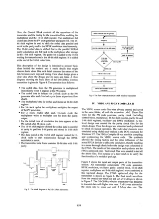
![VI. CONCLUSION
VHDL behavioral modeling is useful in digital systems design
because the designer can model the circuit in a program that
simulates the circuit operation rather than spend time on
complex finite state machines or truth tables. This greatly
facilities and reduces the design time for a large digital
system.
TO_--...l
TATAJ
~
'MP
The simulation waveforms presented in this paper have proven
the reliability of the VHDL implementation to describe the
characteristics and the architecture of the digital transmitter.
The simulated waveforms also have shown the observer how
long the test result can be achieved by using test-bench file.
From the waveforms the digital transmitter transmitted at high
data rates of up to 2 Mbps with the BPSK modulator holding
the data during transmission. The transmitted data included a
1-bit parity that acted as error detection.
PIZ1Th
MI T'
C..........
Last bit appear at the BPSK
output after Is simulation time
-,
*-
Fig. 10. VSS waveform of the transmitter showing the end of I s time
simulation
V. HARDWARE IMPLEMENTATION
The FPGA compiler directory was used for simulation and
synthesis and downloading of the results to the XSV FPGA
board. This board, from Xilinx Virtex FPGA family board,
with a single Virtex FPGA from 50K to 800K contained two
independent banks of 512*16 SRAM for local buffering of
signals and data.
From the optimized FPGA circuit for top-level design, the
circuit of the transmitter was reduced sufficiently for
downloading to the Xilinx FPGA board. From testing, both
hardware and software components performed well and
reliably.
The first step in downloading the design to the Xilinx XSV300 FPGA board was the installation of the software. This was
to install the utility and configuration files for testing and
programming the board. The second step was to configure the
jumpers in the board. The XSV-300 Board came with shunts
on the jumpers in their default arrangement. After this, power
applied to the board from an ATX PC power supply. The next
step was to connect the board to the parallel port of the PC
through a 6-foot DB25 cable. Once the board is connected to
the PC with jumpers in their default configuration, it is now
ready for testing. The last step was to program the interface to
the board and then download the design to the board using the
gxload window of the software. Figure 11 shows the
transmitter after the final step of the downloading in the XCV300 board. The board was tested. The LEDs were used to
show the 16-bit data and 1 -bit parity check at the output of the
transmitter.
REFERENCES
[1] Chang, K., C. (1997), Digital Design and Modeling with VHDL and
Synthesis, IEEE service center, Piscataway.
[2] Cheah, J., Y, C., Practical Wireless Data Modem Design, Artech House
Publishers, Boston, London, 1999.
[3] Feher, K. (1995), Wireless Digital Communications, Prentice Hall, Inc.,
Upper Saddle River, New Jersey.
[4] Gil, H., K., PN Code Acquisition Using Nonparametric Detectors in DSCDMA Systems, Department of Electrical and Electronic, Korea
Advanced Institute of Science and Technology (KAiST), South
Korea,2000.
[51 Halsall, F., Data Commuunications, Computer Networks and Open Systems,
Addison-Wesley Publications company, Harlow, England, 1996.
[6] Jakes, W. C., Jr. (1994), Microwave Mobile Communications, J. Wiley &
Sons, New York, 1974; reprinted by IEEE Press, 1994, ISBN 0-78031069-1. http://www.cdg.org. Accessed on 2 Oct. 2001.
[71 Oianpera, T., Prasad, R., Wideband CDMA for Third Generation Mobile
Communications, Artech House Publishers, Boston, London, 1998.
[8] Rushton, A., VIDL for Logic
Chichester, England,1998.
Synthesis,
John Wiley & Sons Ltd,
[9] Zwolinski, M. (2000), Digital System Design with VHDL, Pearson
Education Ltd., England.
Fig. 1. The FPGA board after downloading the simulated and synthesizes
VHDL files of the transmitter
636](https://image.slidesharecdn.com/cdma-140201231007-phpapp02/85/Cdma-5-320.jpg)