Download as PPSX, PPTX

The document provides an overview of the Common Channel Signaling System #7 (CCS#7), detailing its evolution, architecture, features, and functionalities as a critical digital signaling protocol for telecommunications. It outlines the layered structure of CCS#7, the types of signaling modes, and various components such as Service Switching Points (SSPs) and Signal Transfer Points (STPs). Additionally, it touches on the history of signaling protocols and the transition from in-band to out-of-band signaling to enhance security and performance in telecommunication networks.
Title slide introducing CCS #7, with presenter details.
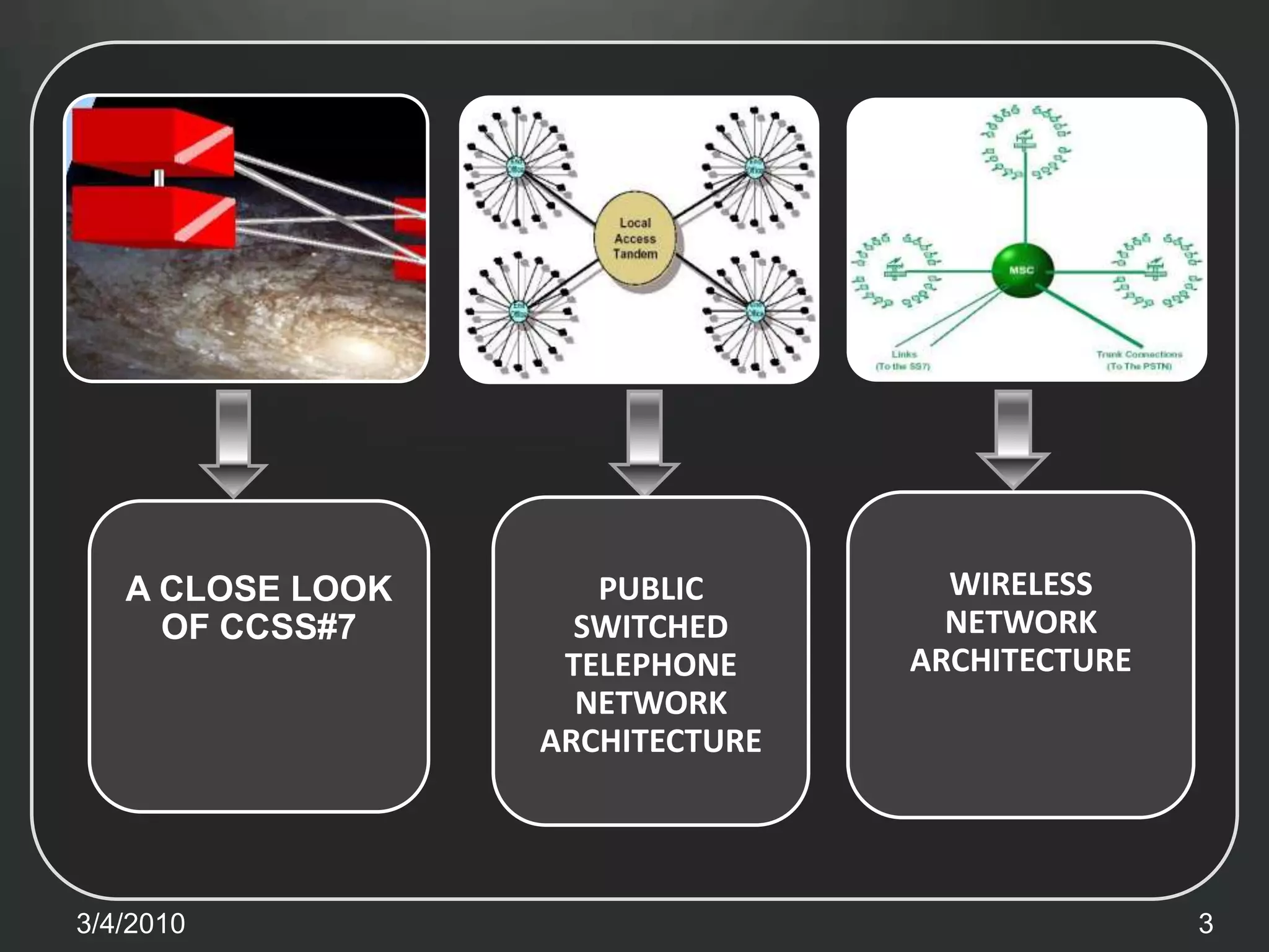
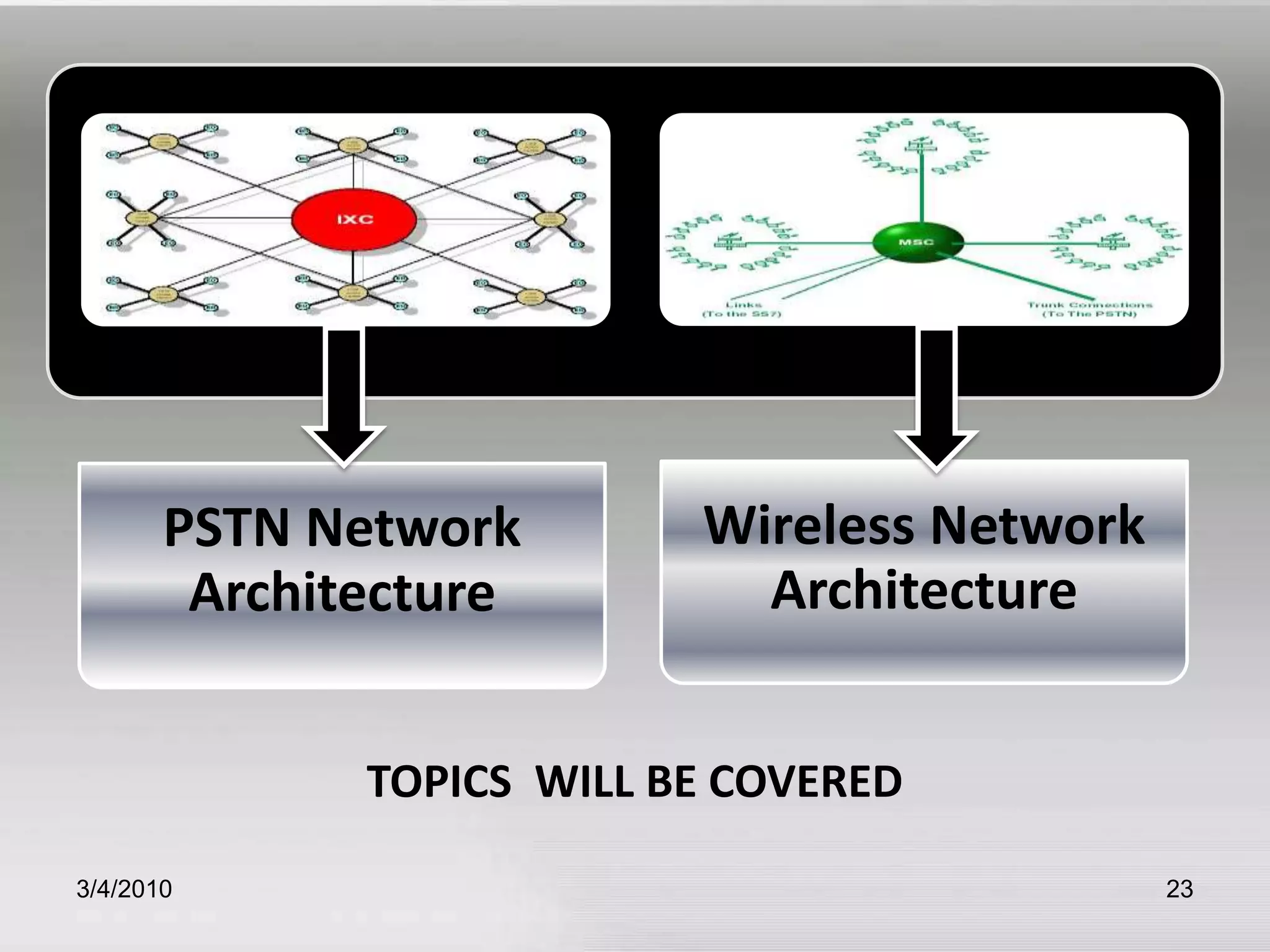
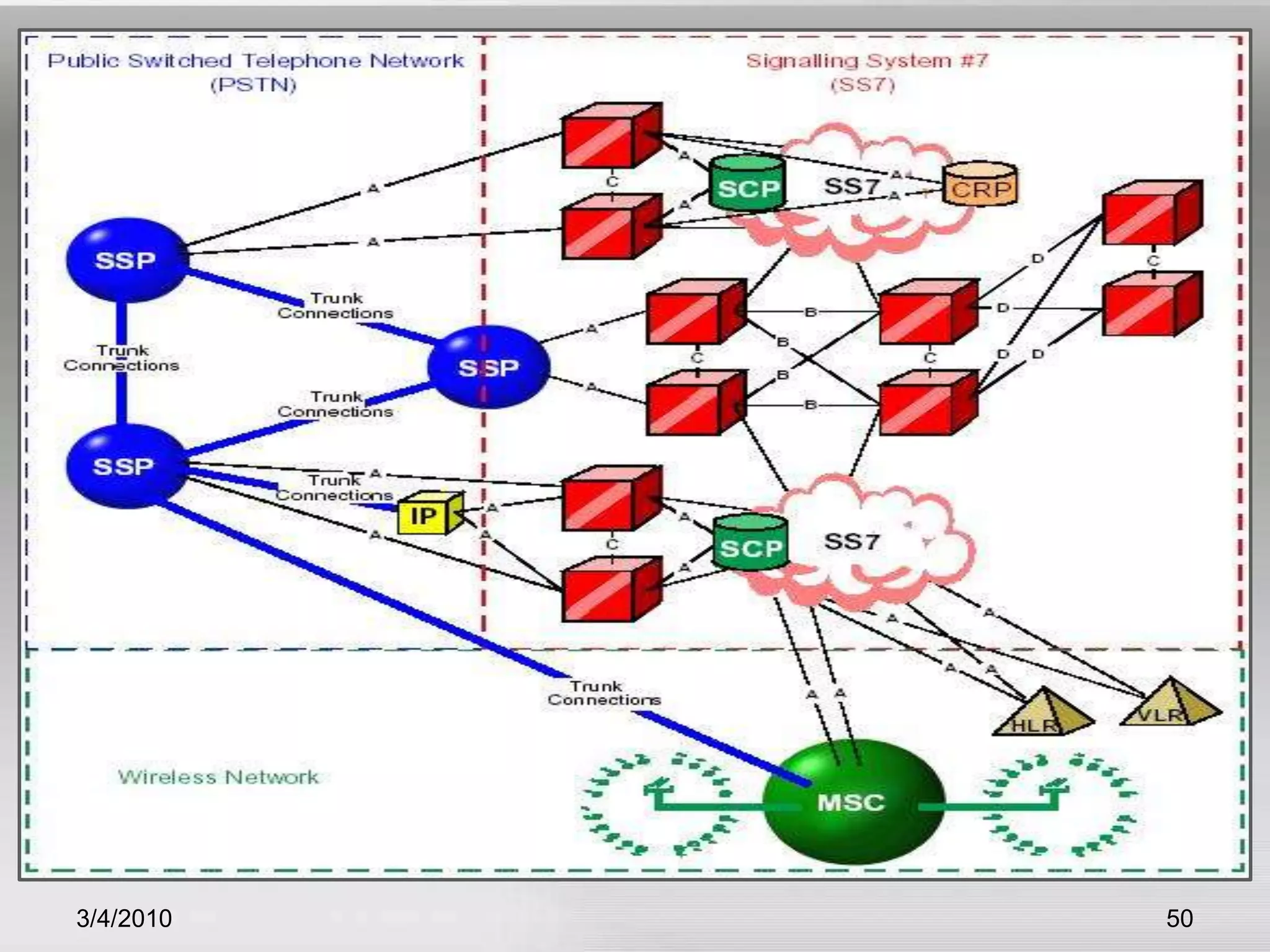
Discusses wireless network architecture and PSTN architecture, focusing on CCSS#7.
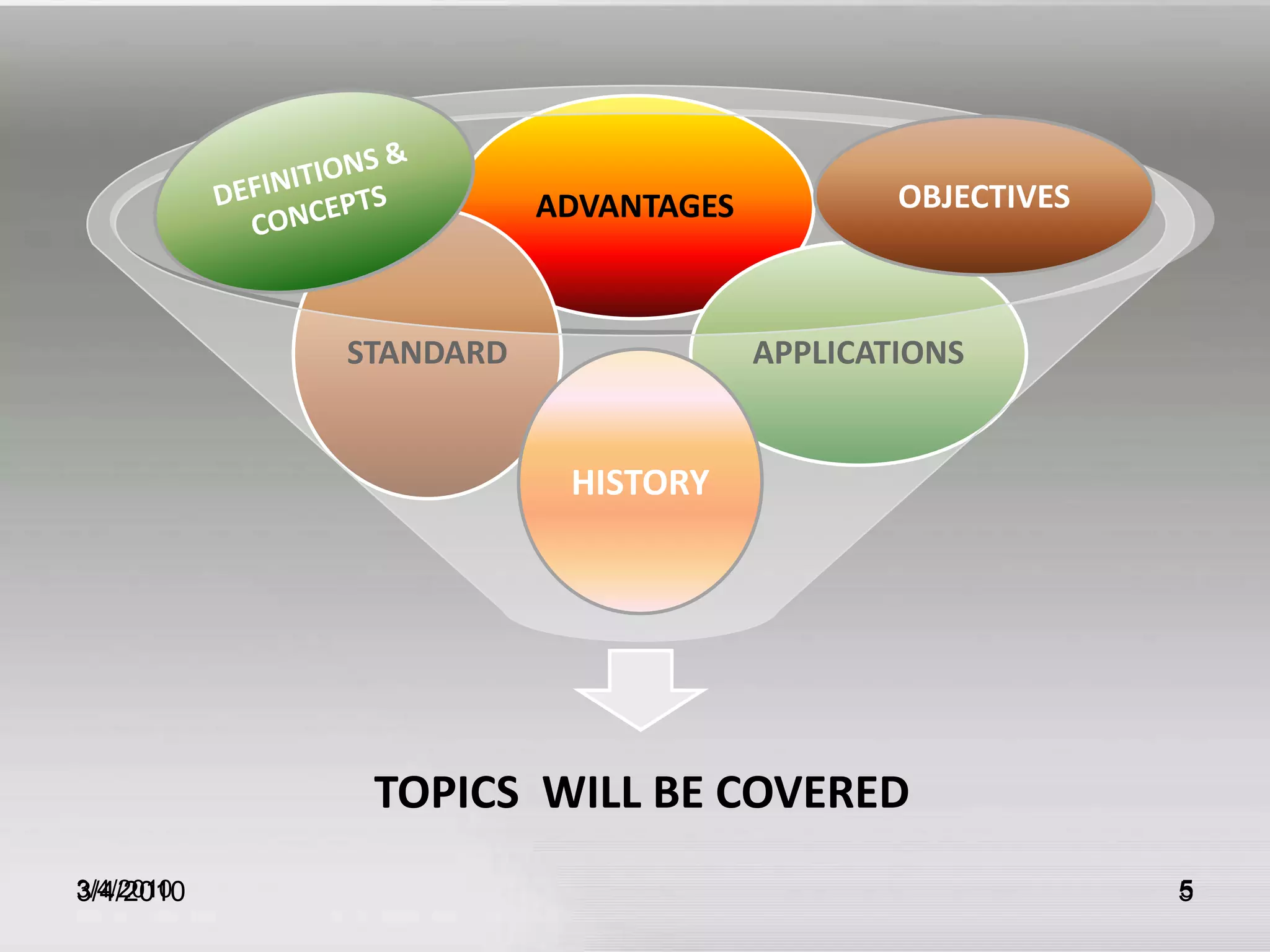
Definitions, concepts, objectives, and historical context of CCSS#7.
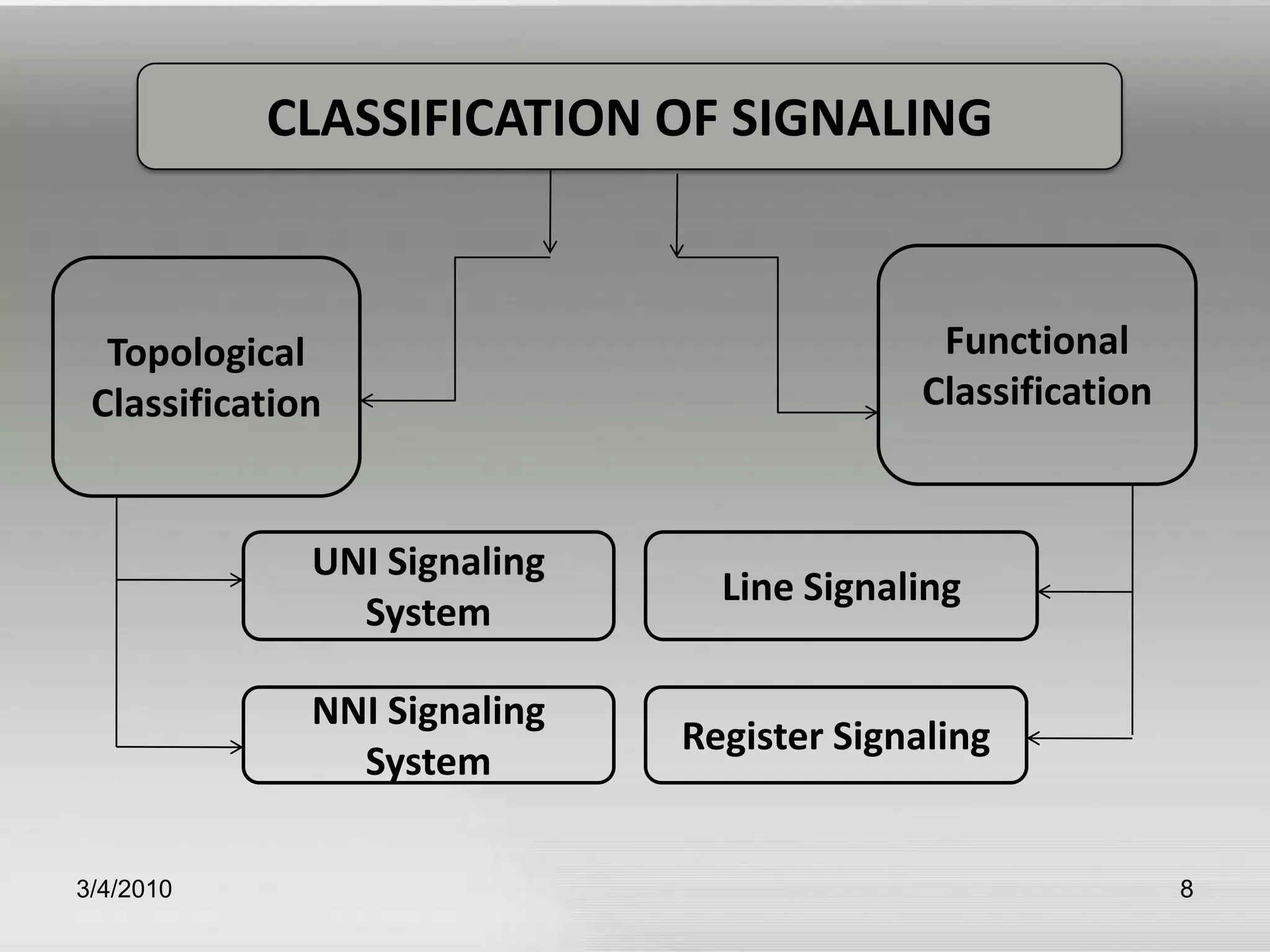
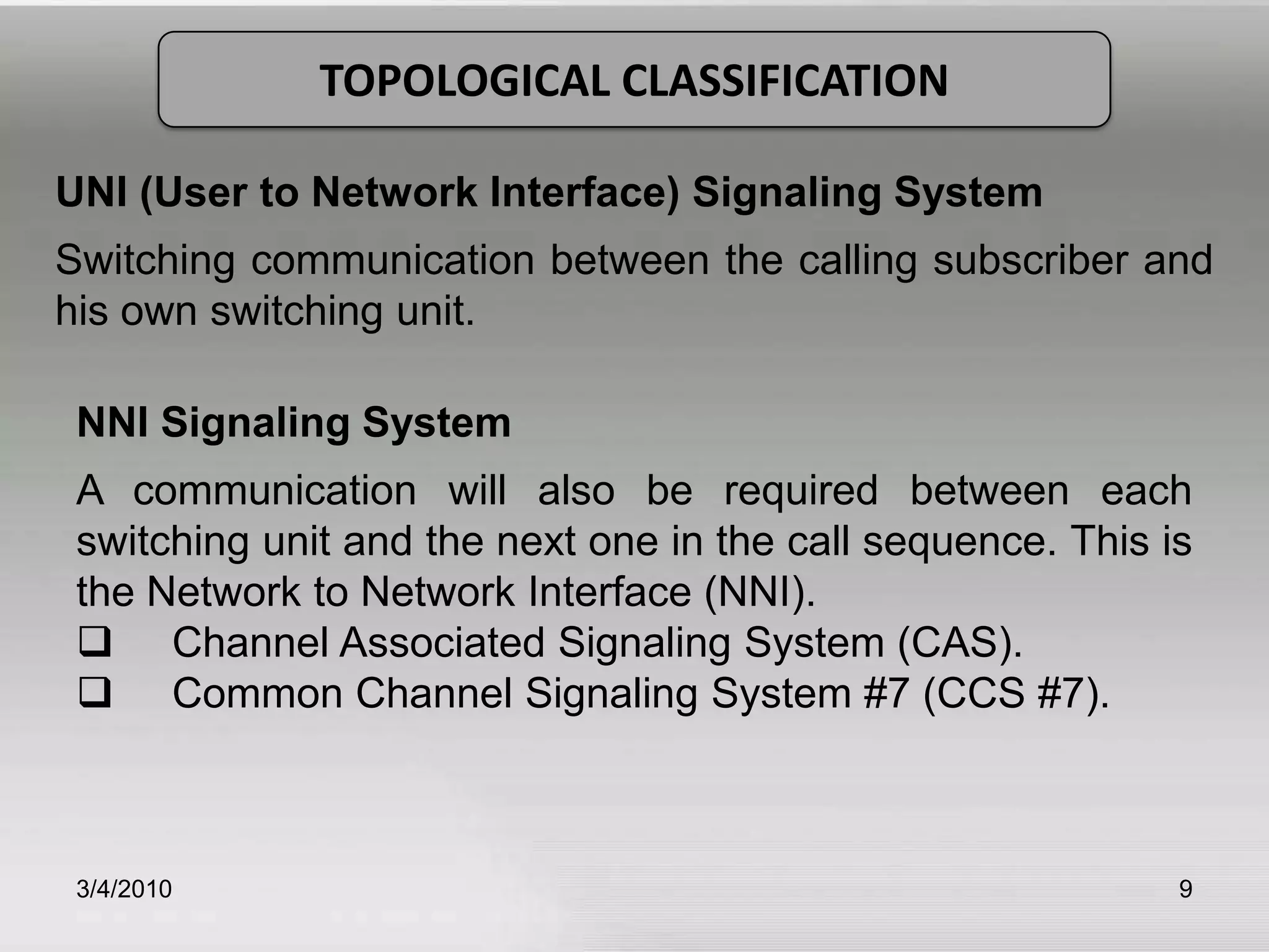
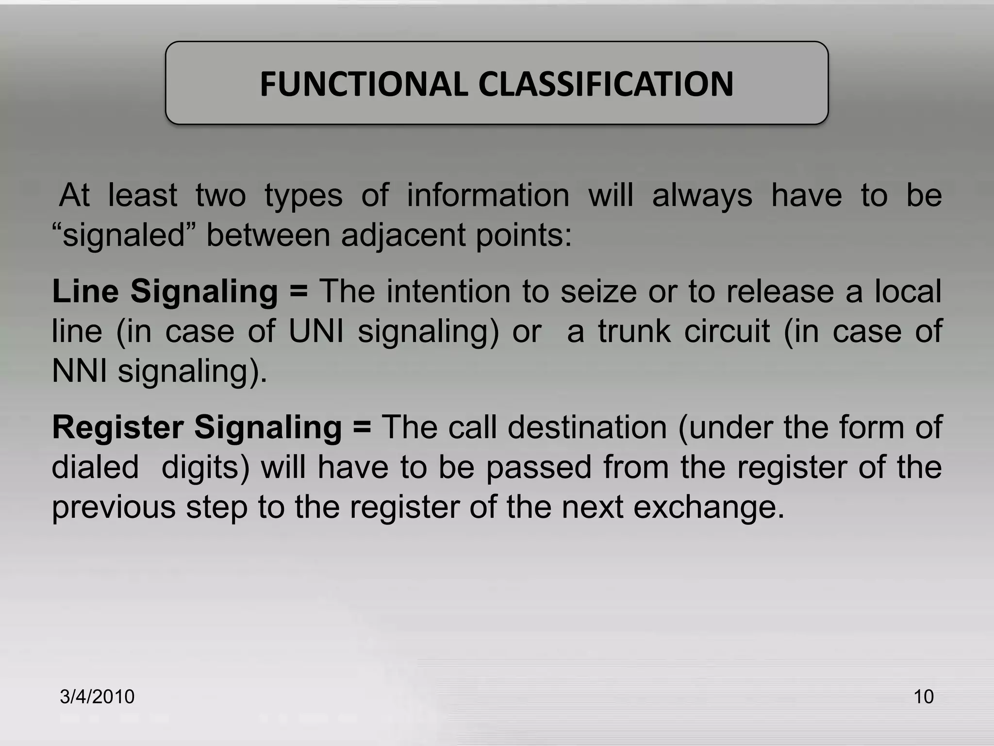
Overview of signaling in telecommunications, classifications including line and register signaling.
Explains in-band and out-band signaling, and various signaling modes used in telecommunication.
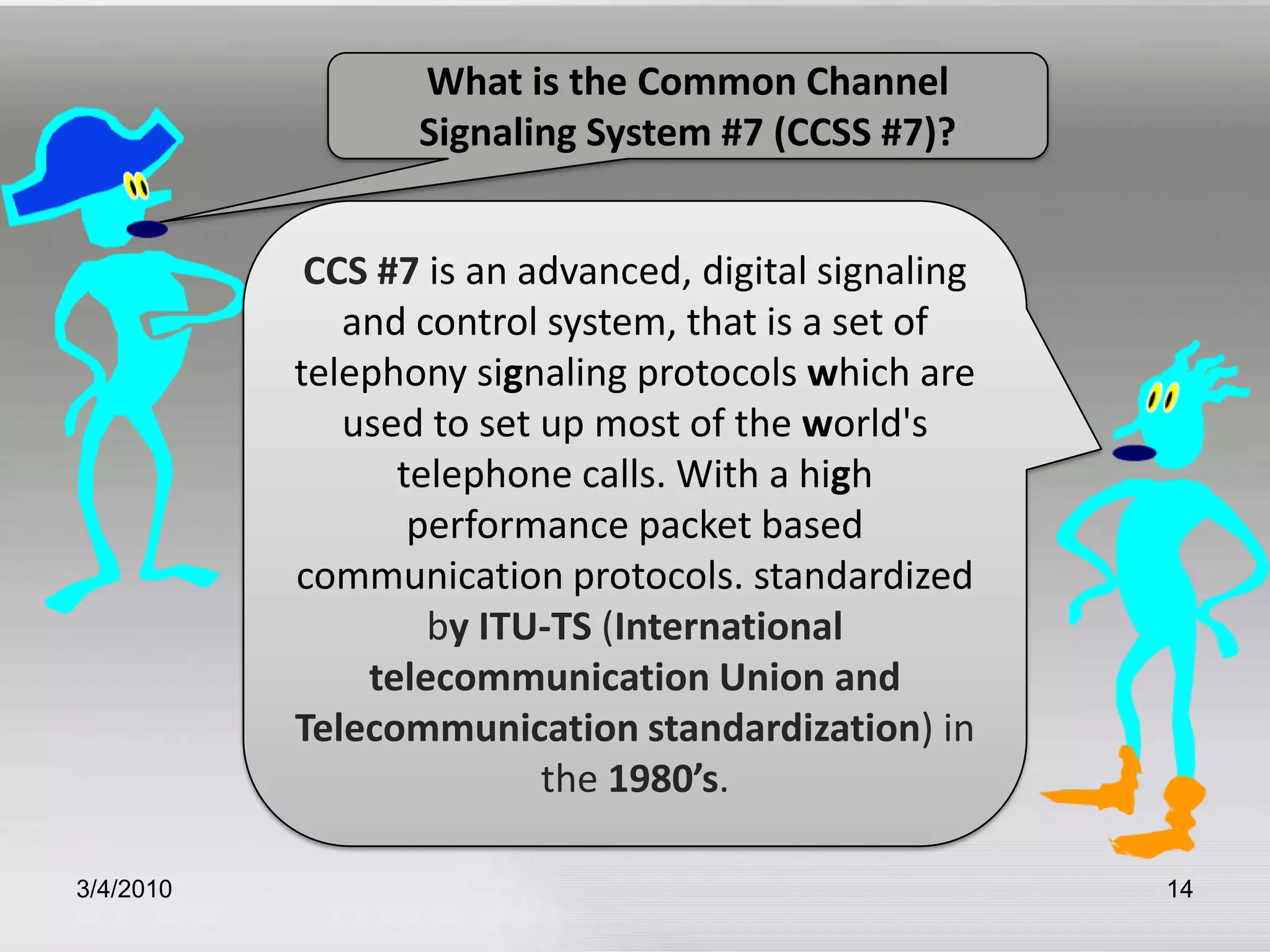
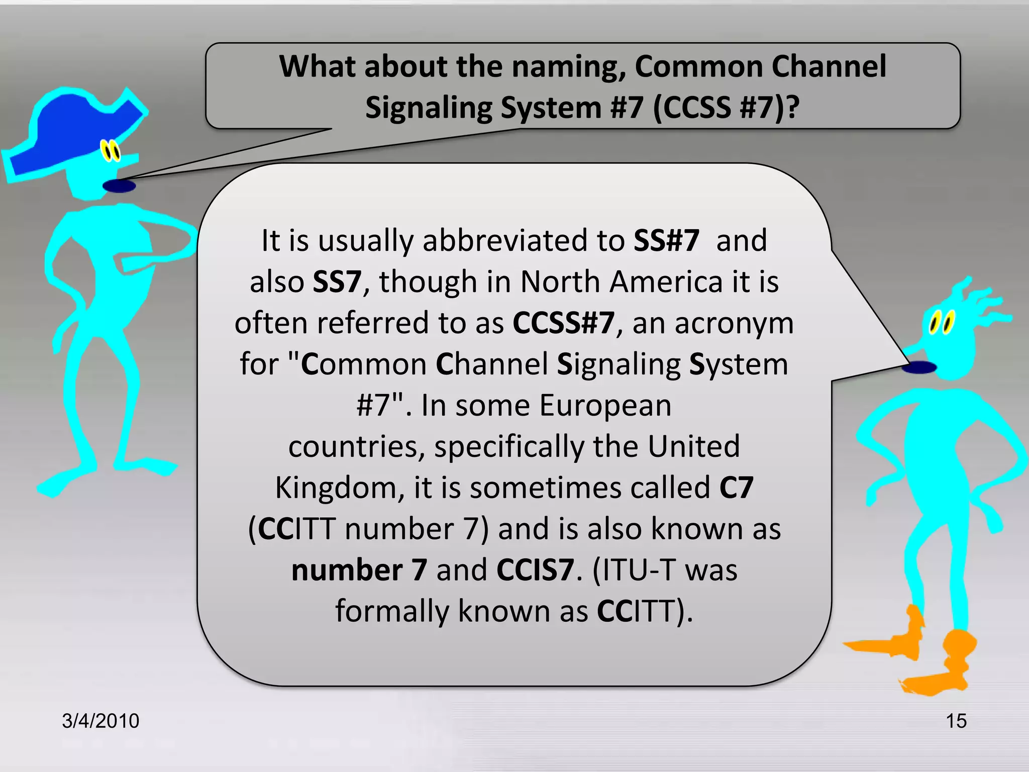
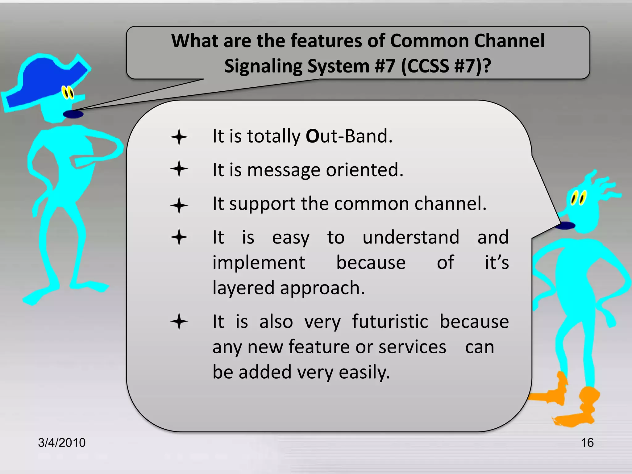
Describes what CCSS#7 is, its naming conventions, and its key features.
The evolution of CCSS#7 from earlier signaling systems and standards established by ITU-T.
Functions of SS7 protocol in call management and related services like call forwarding.
Highlights operational benefits and suitability of CCS #7 for digital and analog communications.
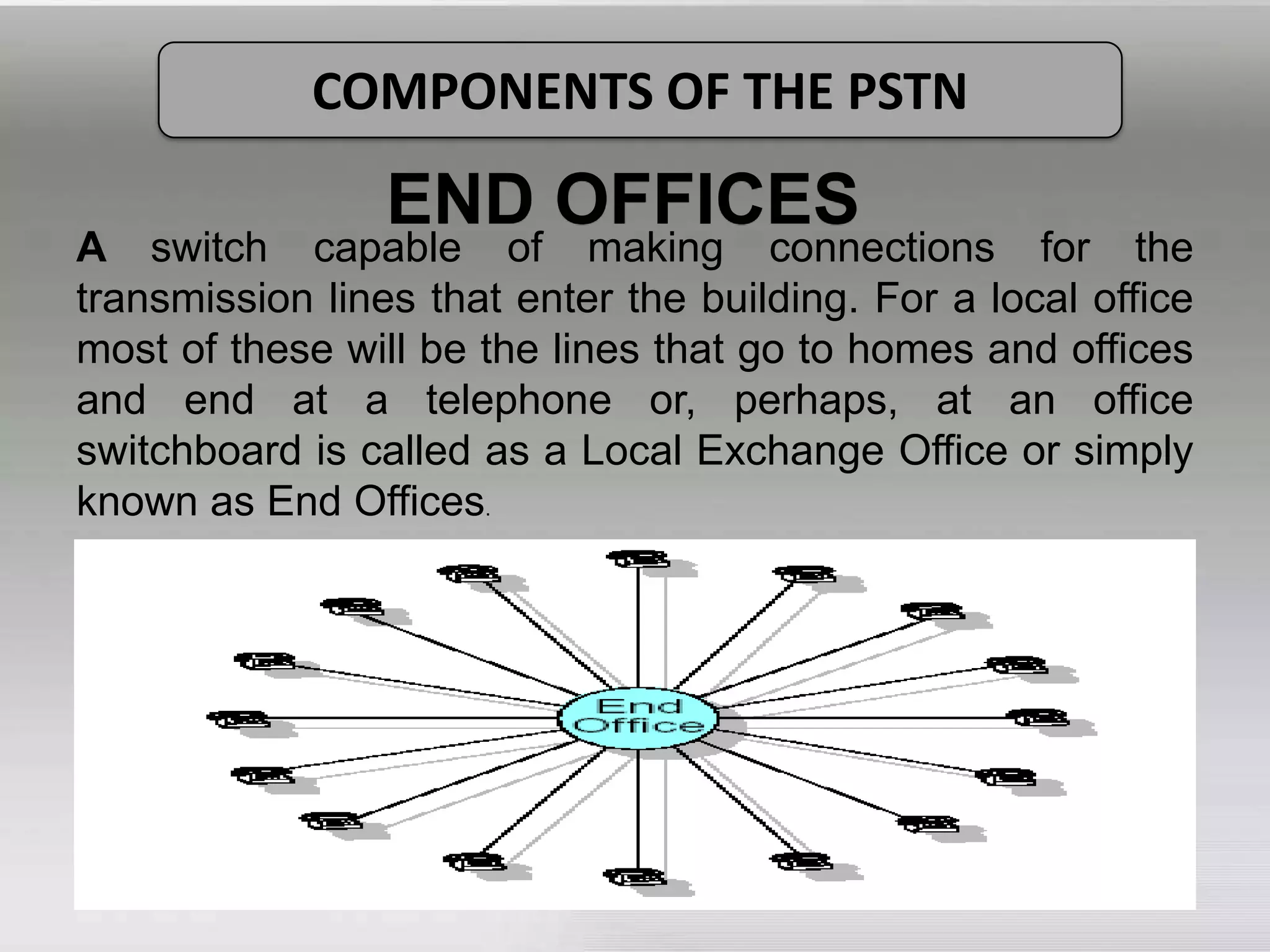
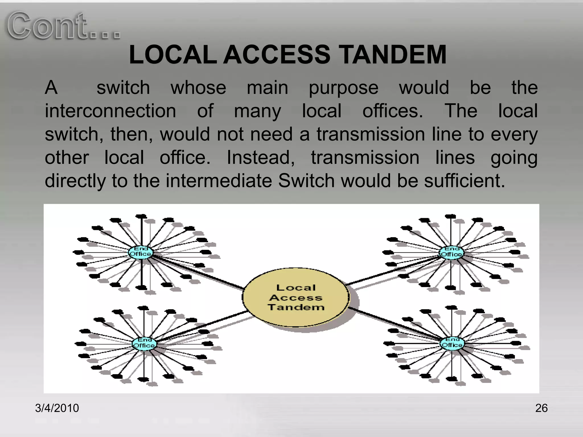
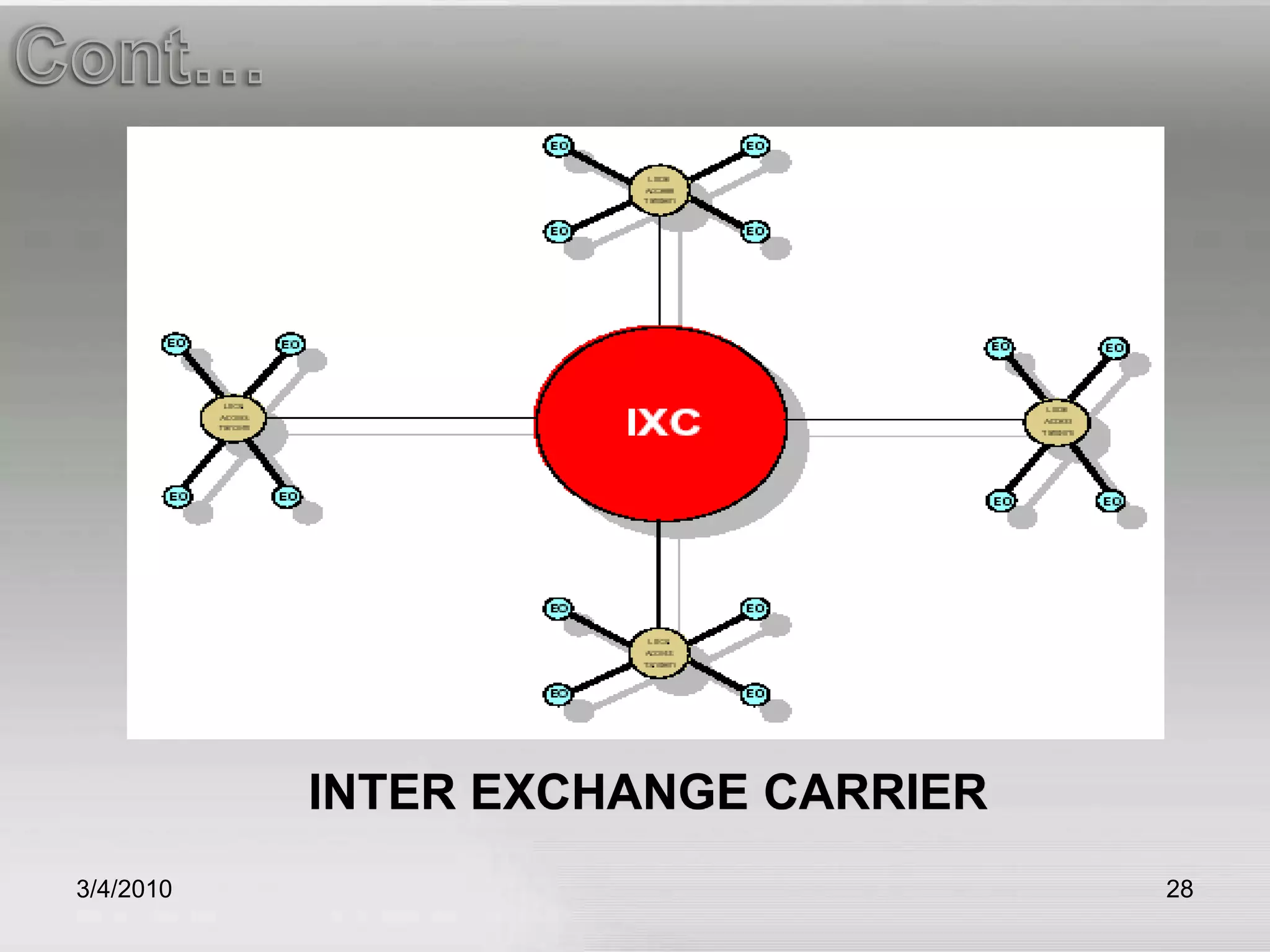
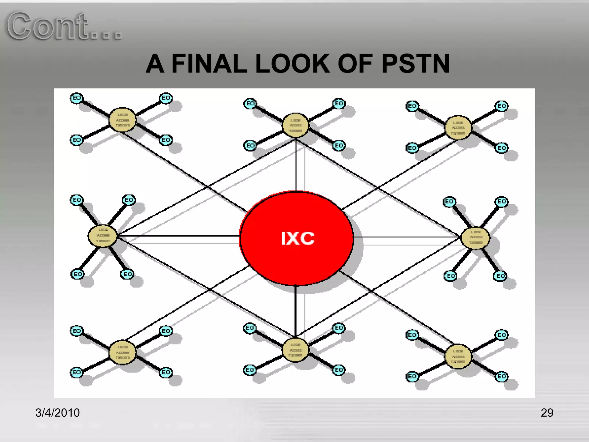
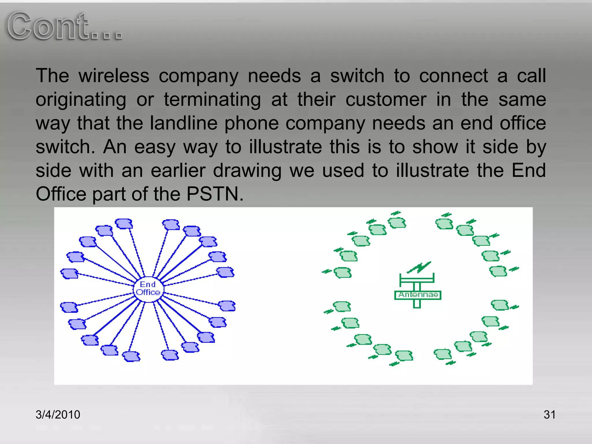
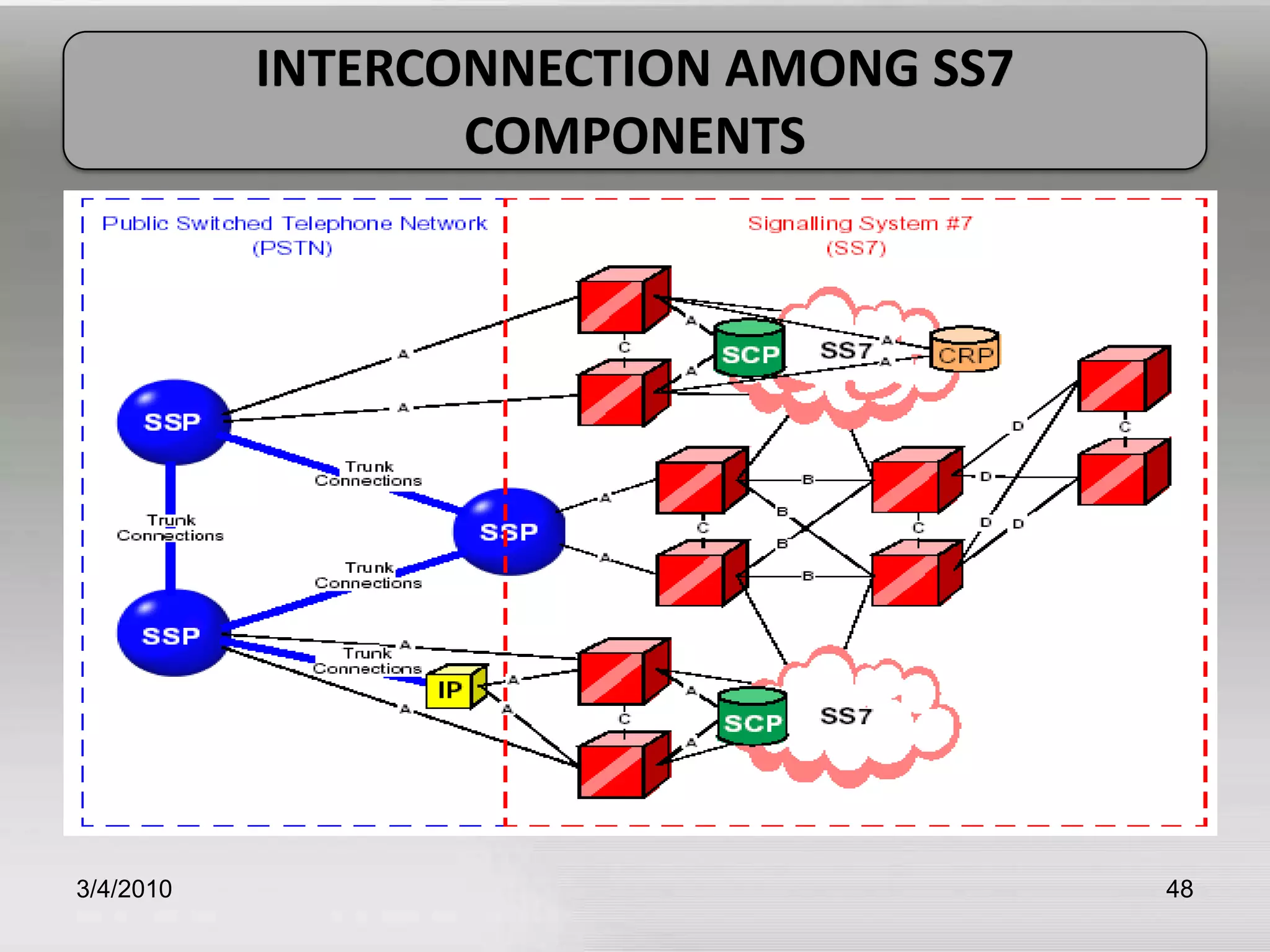
Detailed look at the components of the PSTN including end offices and inter exchange carriers.
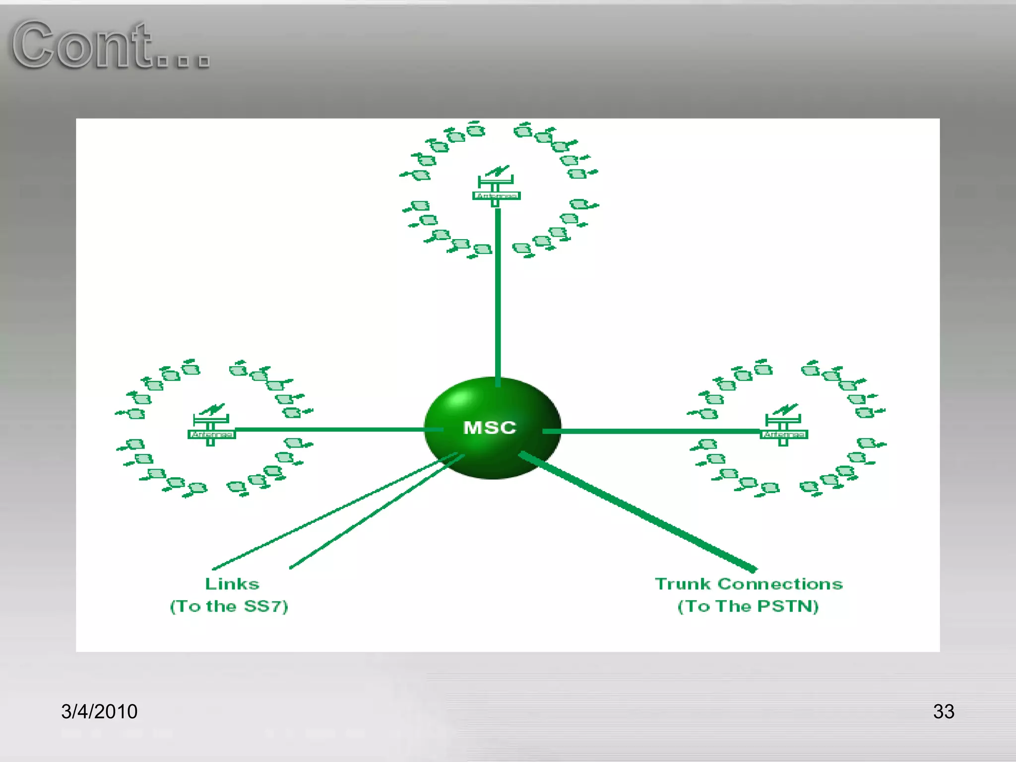
Explains the structure and components of wireless networks, including their integration with PSTN.
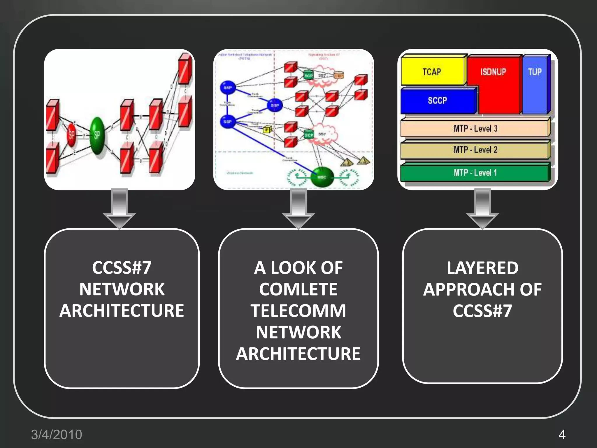
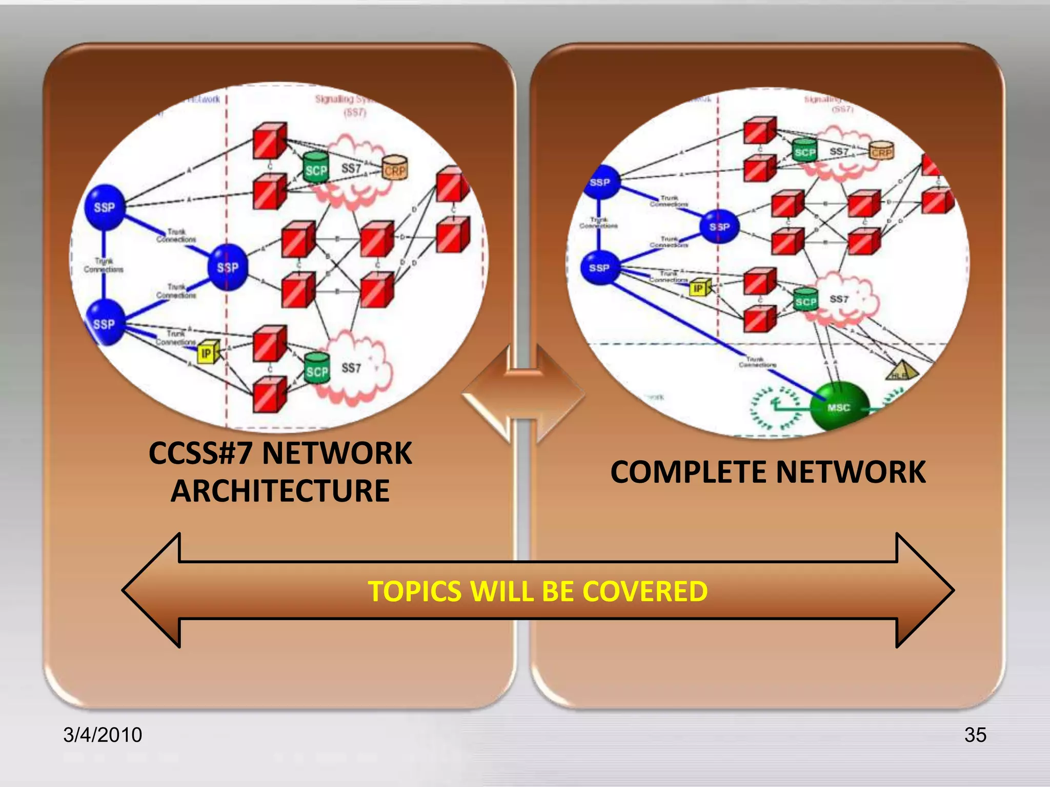
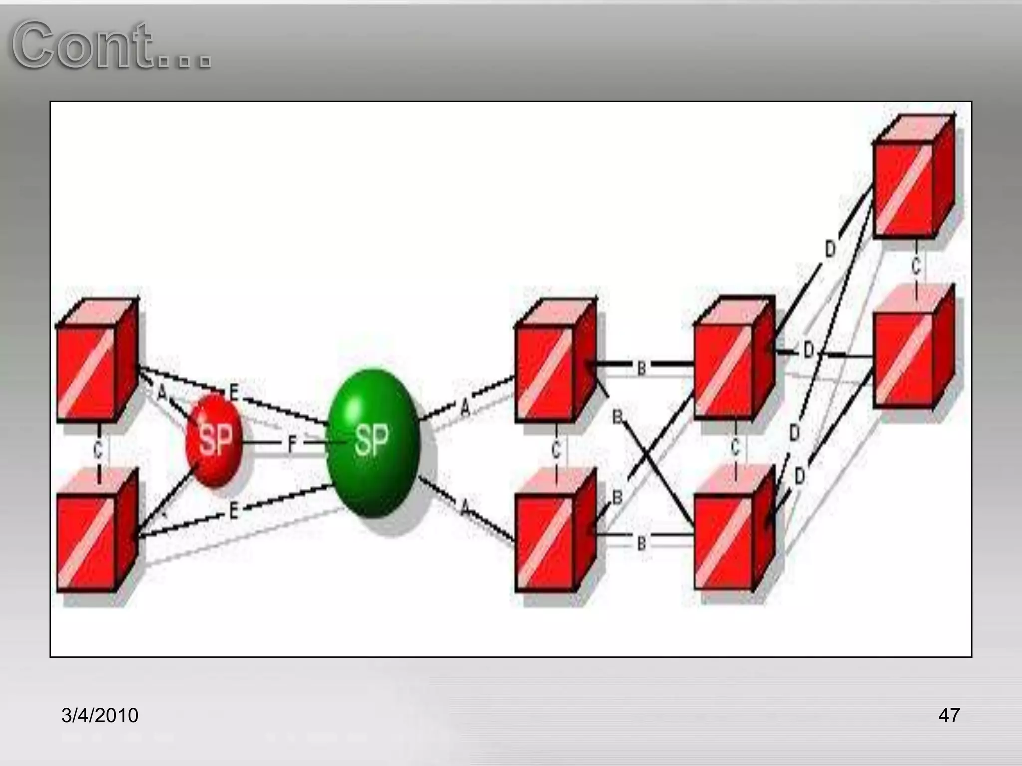
Describes the architecture of CCSS#7 networks and the role of signaling points like STPs and SCPs.
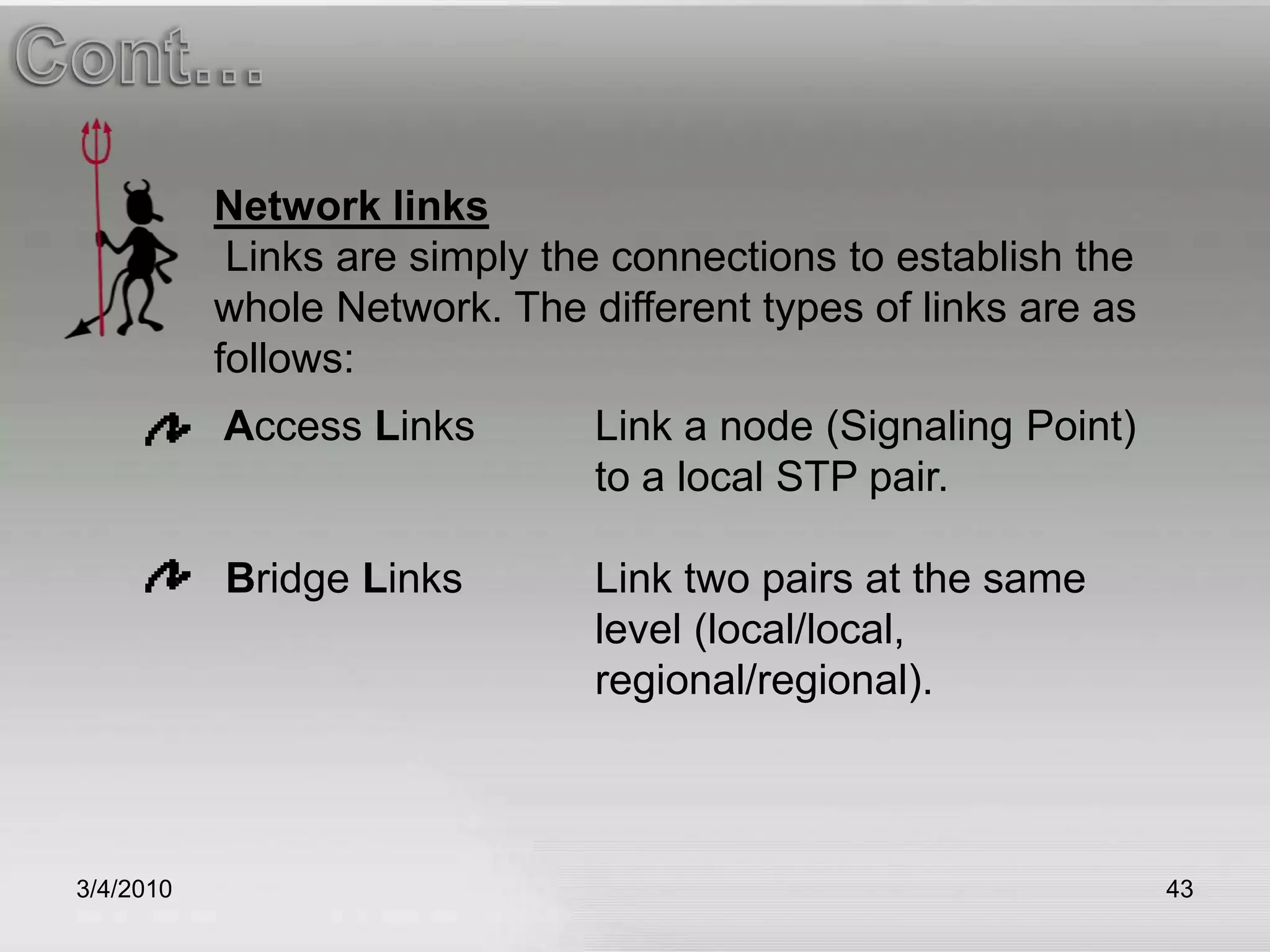
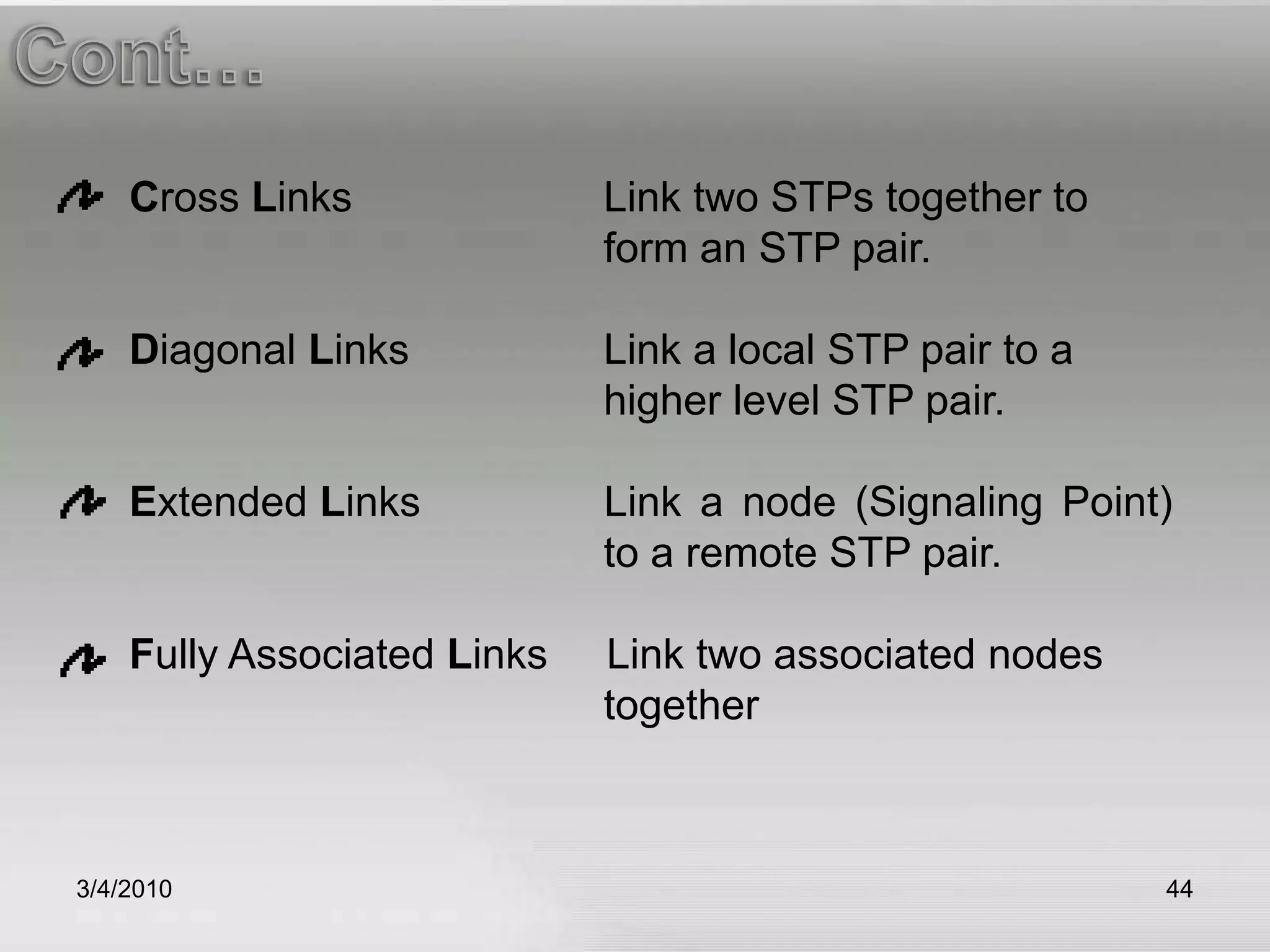
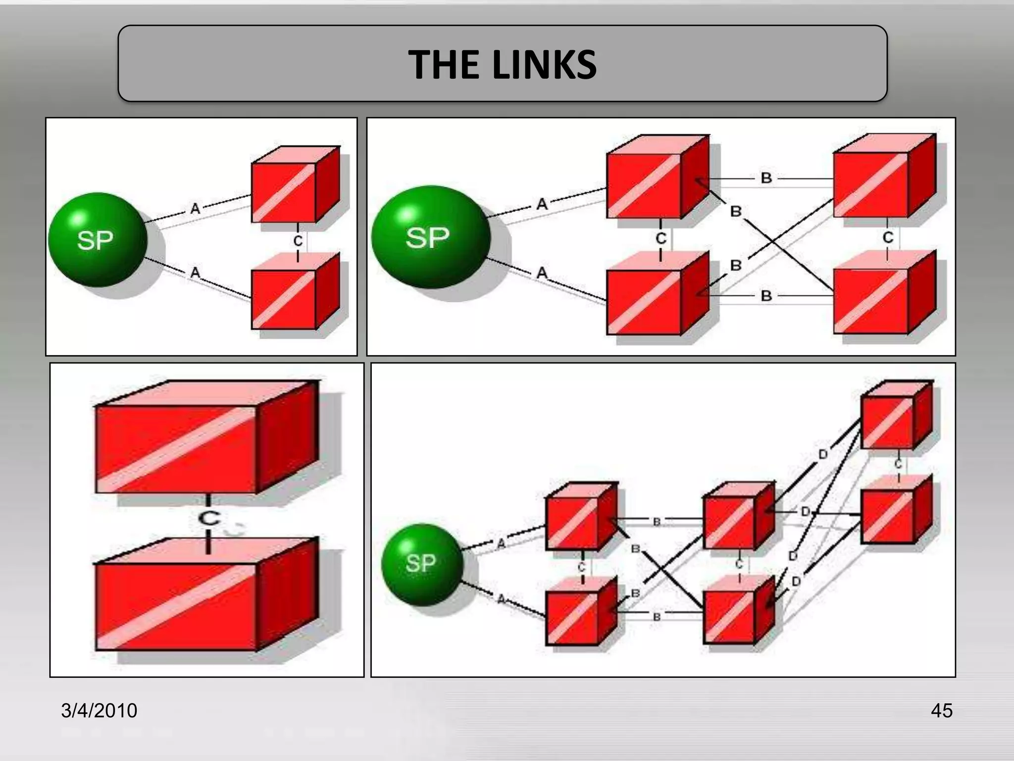
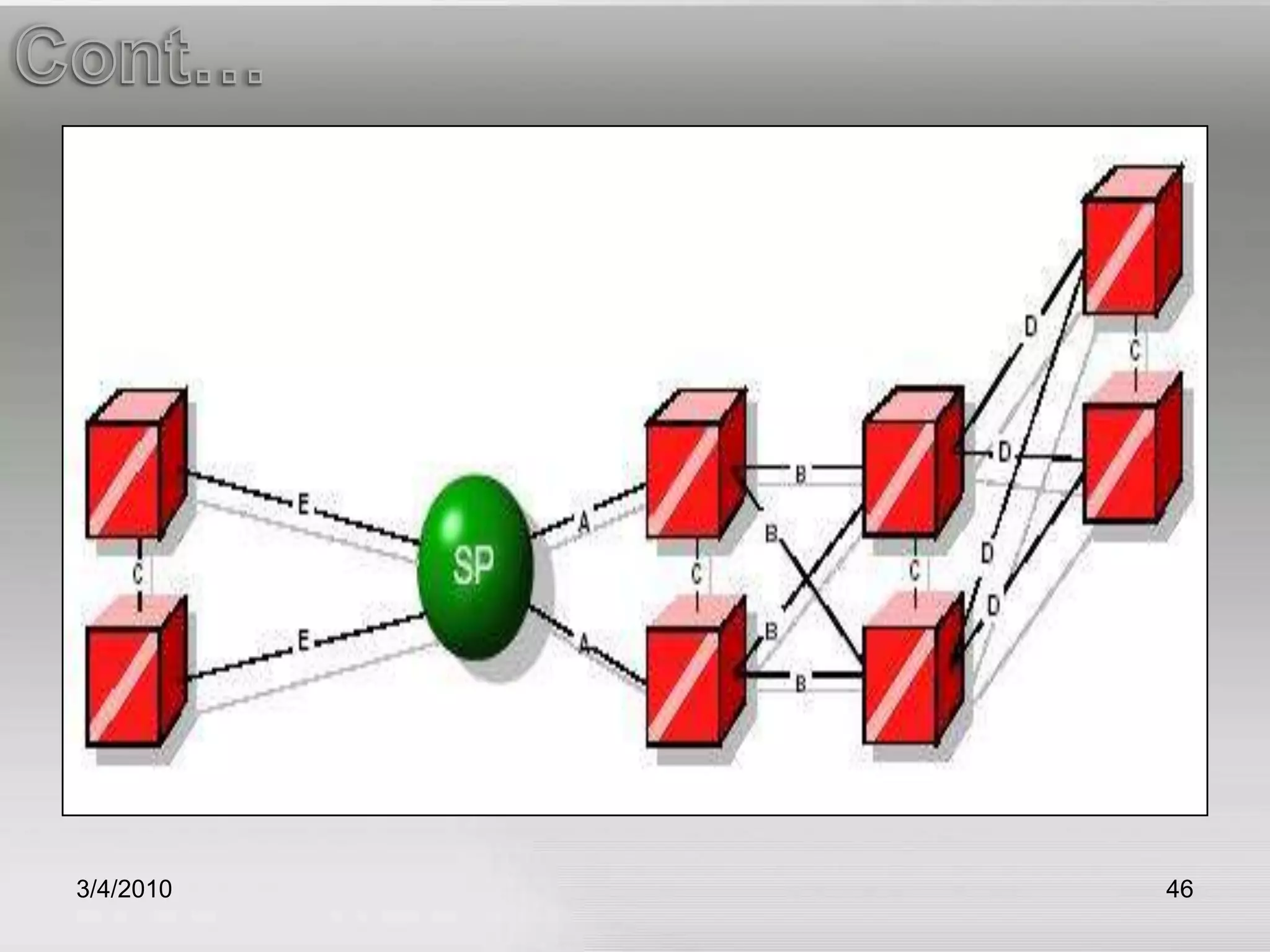
Overview of various types of network links essential for SS7 communication.
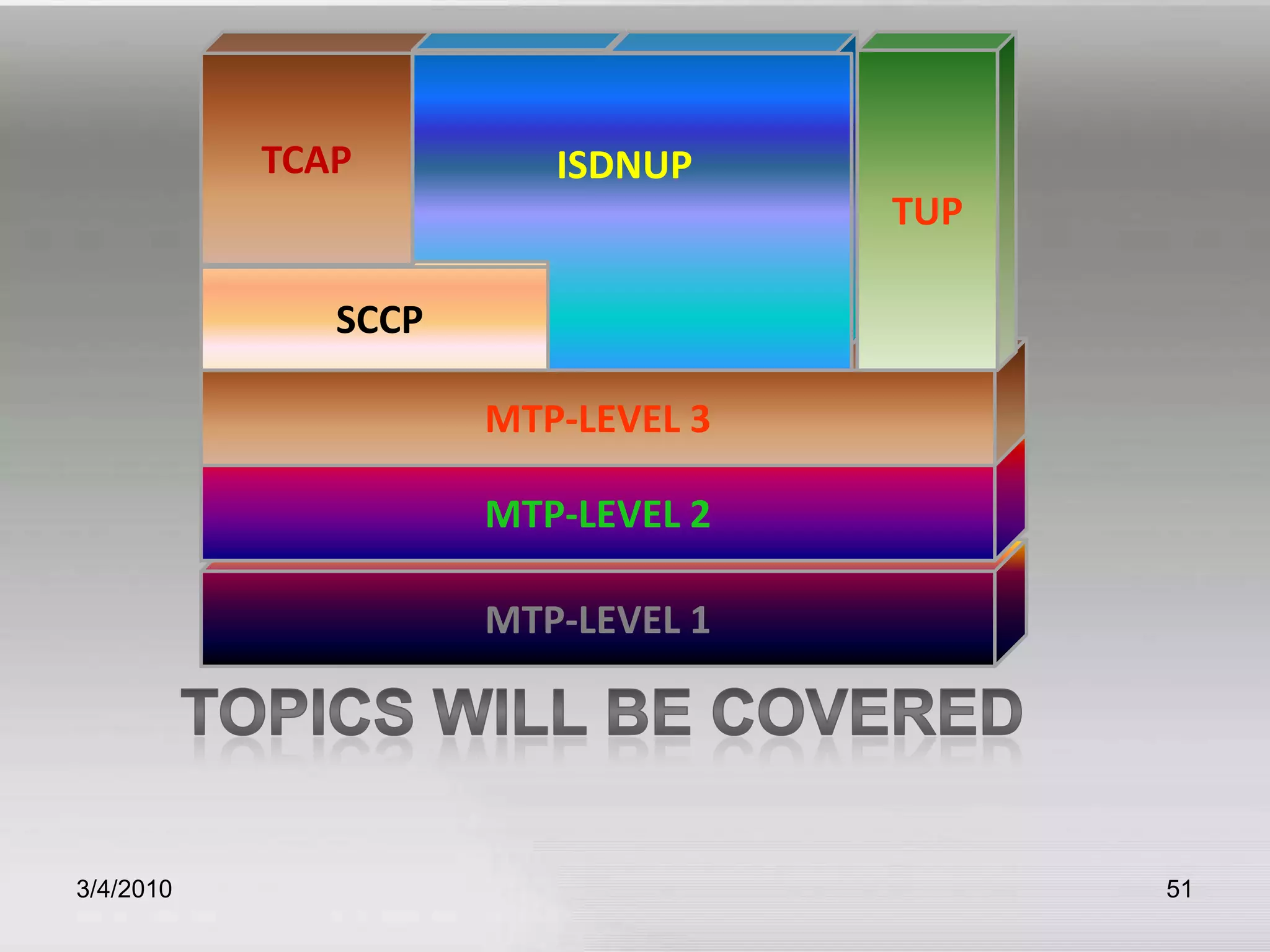
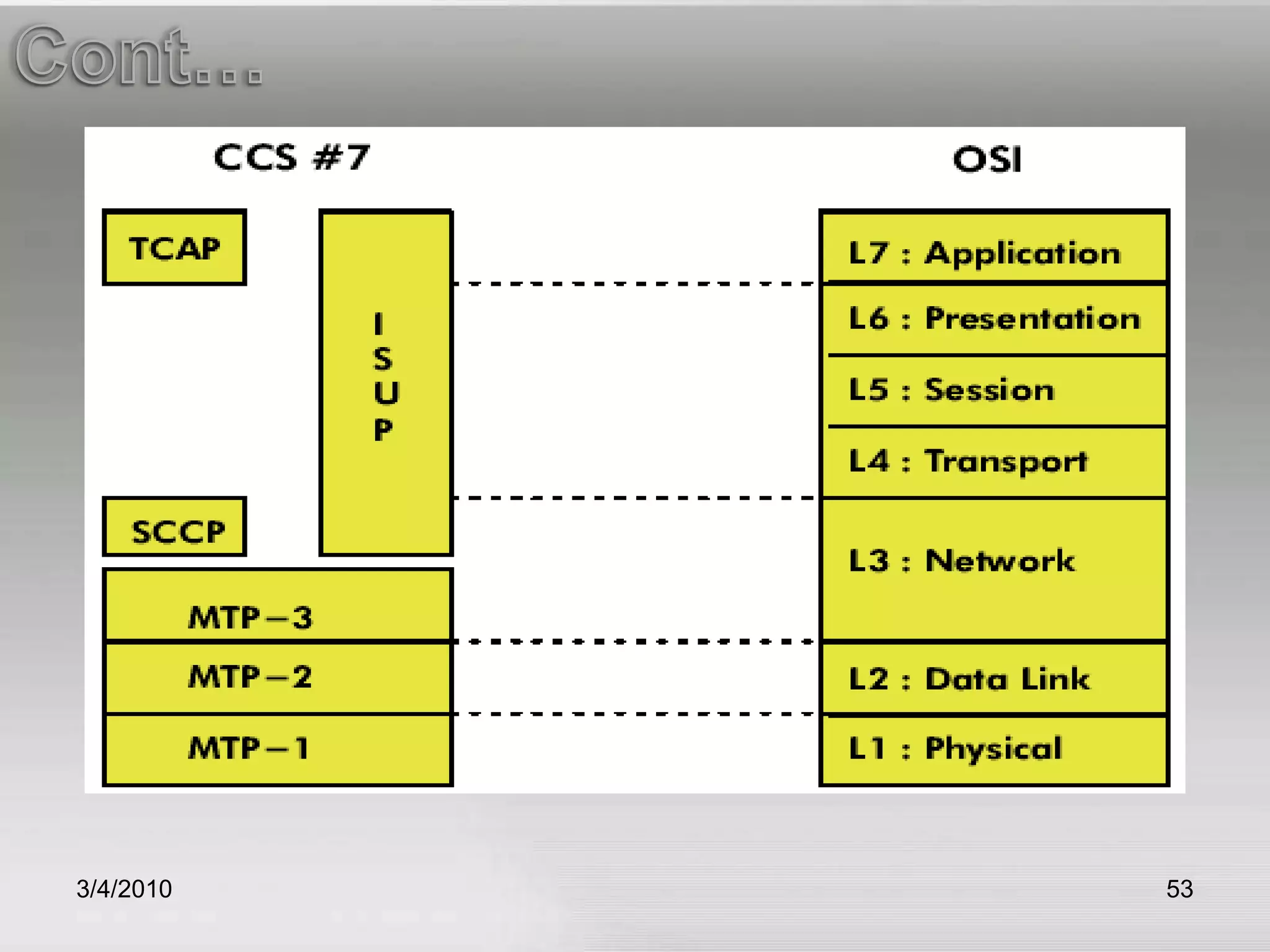
Comparative analysis of CCSS#7 signaling functions with the OSI model's structure.
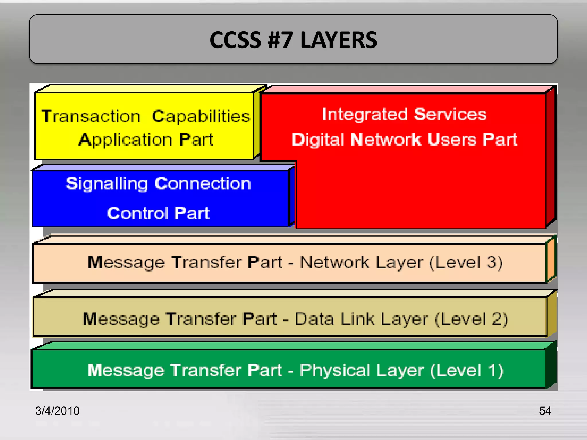
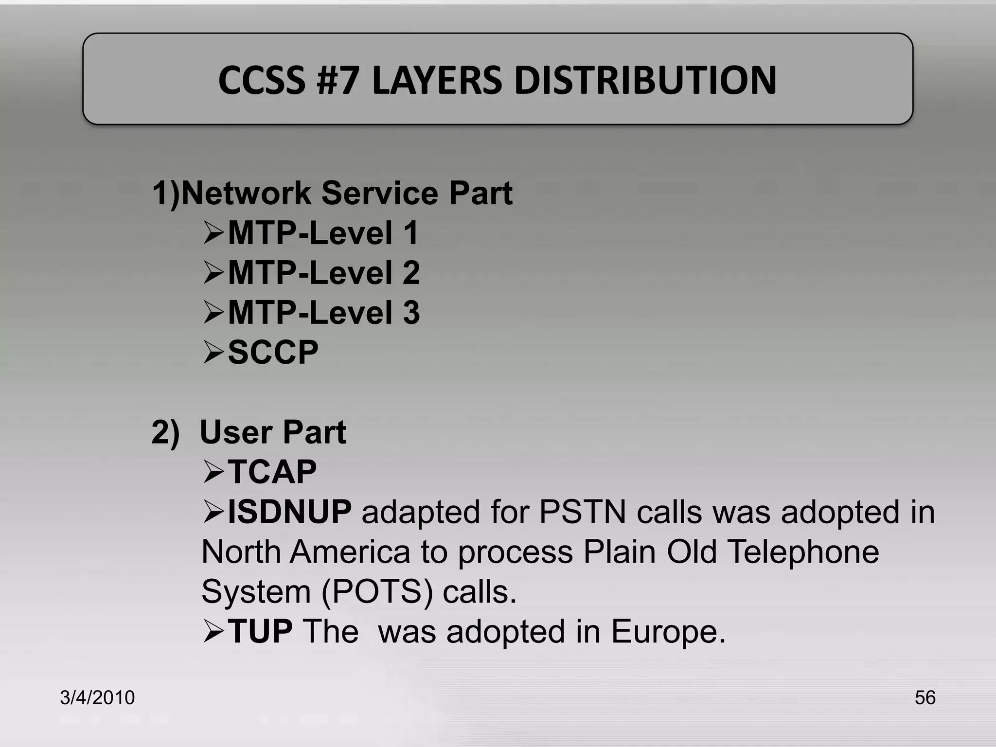
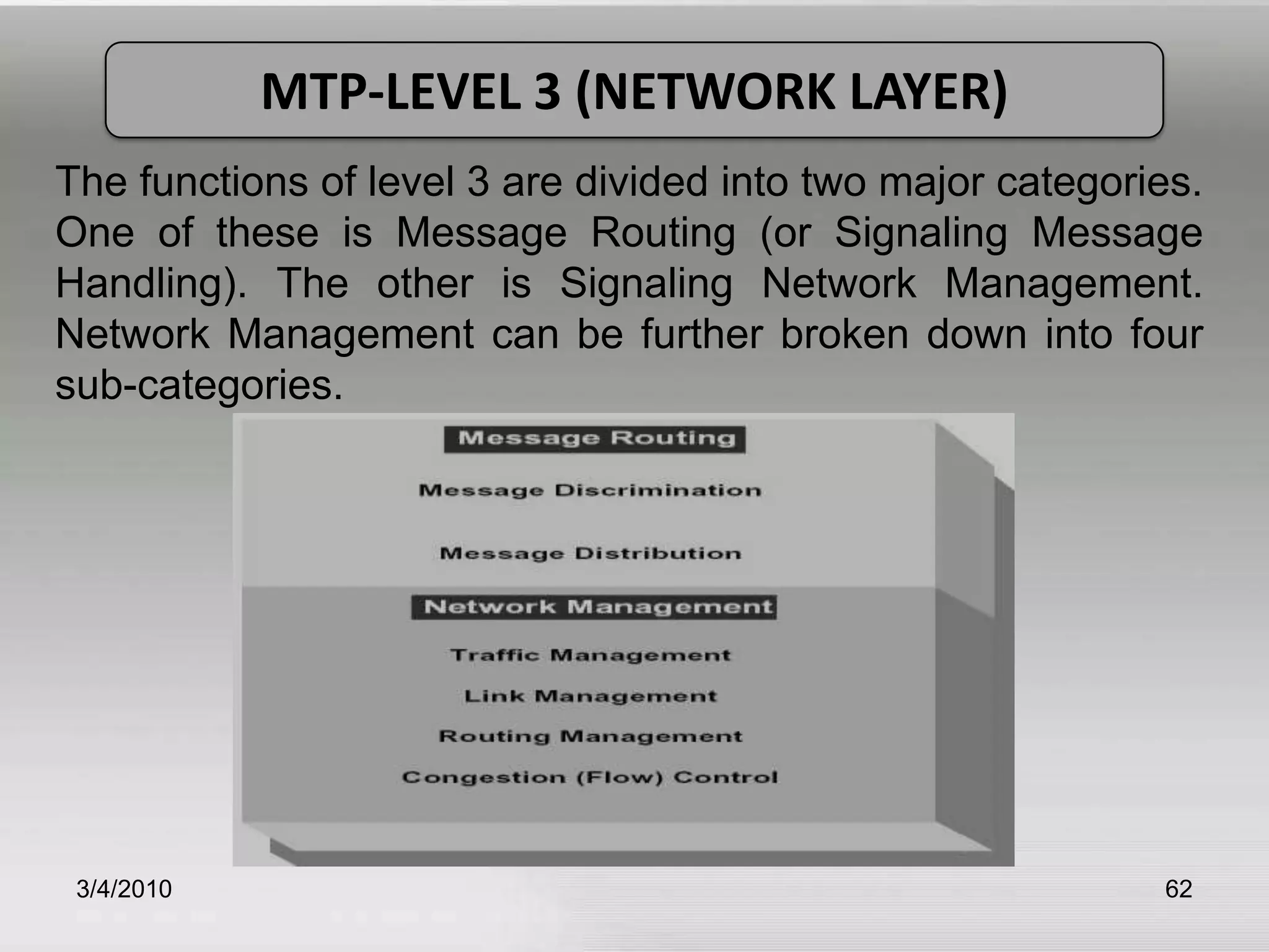
Detailed functionalities of MTP layers including physical, data link, and network layers.
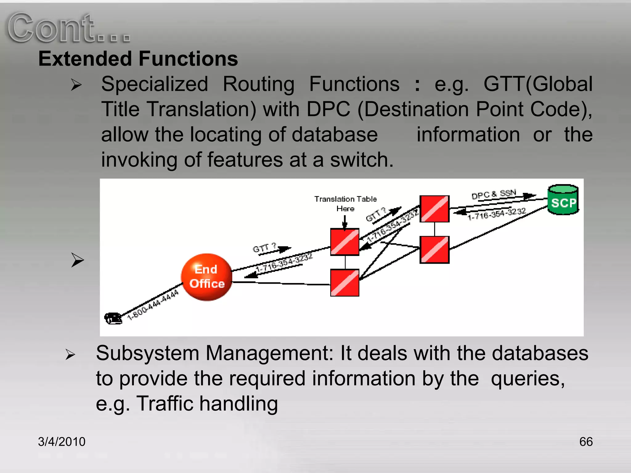
Describes SCCP and TCAP in SS7 related functions including routing and database queries.
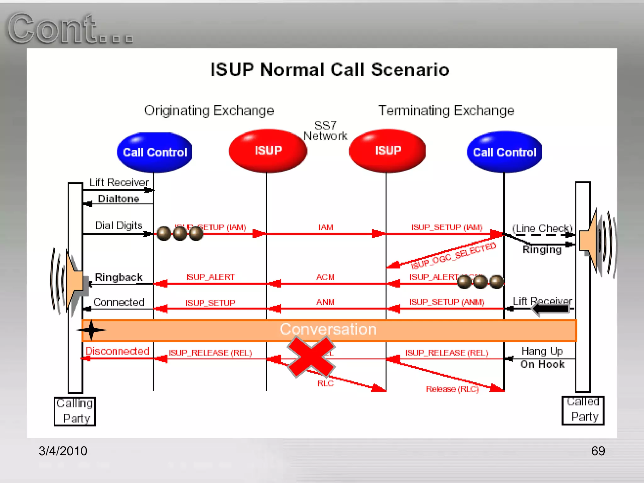
Overview of ISDN User Part and Telephone User Part functionalities within CCSS#7.
Final slide with references and appreciation for the presentation.