Download to read offline
![1.2.1 Speech Analysis
In speech recognition, the frequency content of the
detected word has to be analyzed. Several 4th
order
Chebyshev band pass filters are created by cascading
two 2nd
order filters using the following Direct Form
II Transposed realization of difference equations.
( ) ( ) ( )
( ) ( )
( ) ( ) ( )
( ) ( )
( ) ( )
Coefficients a’s and b’s used in the above equations
was obtained using the following syntax in Matlab.
[B,A] = cheby2(2,40,[Freq1, Freq2]);
cheby2 designs Chebyshev Type II digital filter using
the given specifications, 2 defines a 4th
order filter, 40
defines the stop band ripple in dB, and Freq1 and
Freq2 are the normalized cutoff frequencies. The
tf2sos function is then used to convert the transfer
function of the filter to a 2nd
order section version.
1.2.2 Voice-fingerprint Calculation
Due to the limited RAM on the ATMega32, the
relevant information of each spoken word had to be
encoded in the form of a ‘fingerprint’. To compare
fingerprints, the following pseudo Euclidean distance
formula was used between the fingerprint of stored
and sampled word to find correct word.
∑| |
where, P = (p1, p2, ..., pn) is the dictionary fingerprint
and, Q = (q1, q2, ..., qn) is sampled word fingerprint.
pi and qi are the fingerprint data points. To see if two
words are the same, the distance between them are
computed and the words with the minimum distance
in the database are considered to be the matching
word. Original Euclidean distance requires squaring
the difference between two points. Fixed point
arithmetic produces too large a number, causing the
variables to overflow. Thus a modified formula was
used by neglecting the square root and the square
which practically showed satisfactory results.
1.2.3 ARC4 Cryptography
ARC4 is one of the most widely used software stream
ciphers in many encryption schemes, including WEP,
WPA, and SSL. The main factors in ARC4's success
over such a wide range of applications are its speed,
simplicity and efficiency in software and hardware.
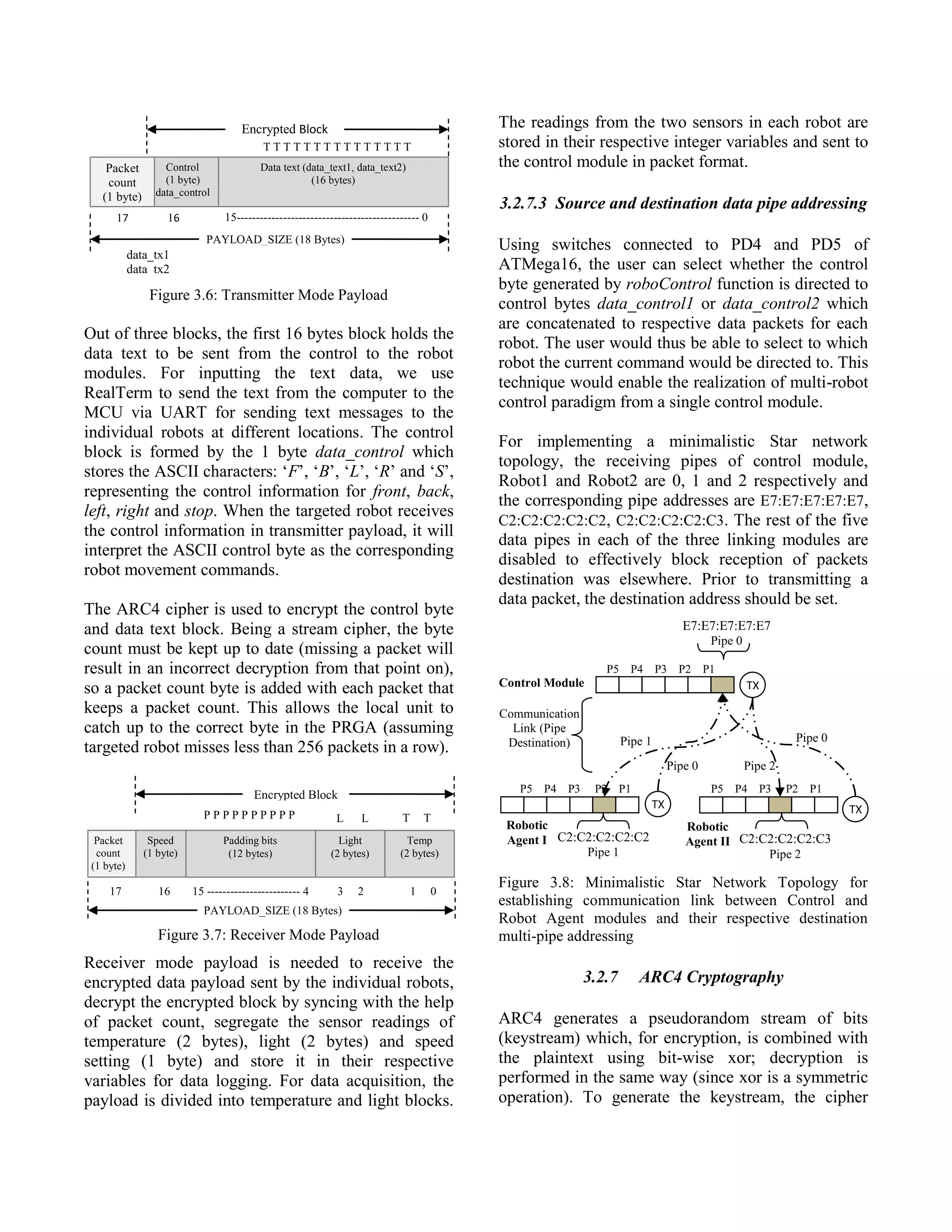
3. DESIGN AND IMPLEMENTATION
3.1 HARDWARE ARCHITECTURE
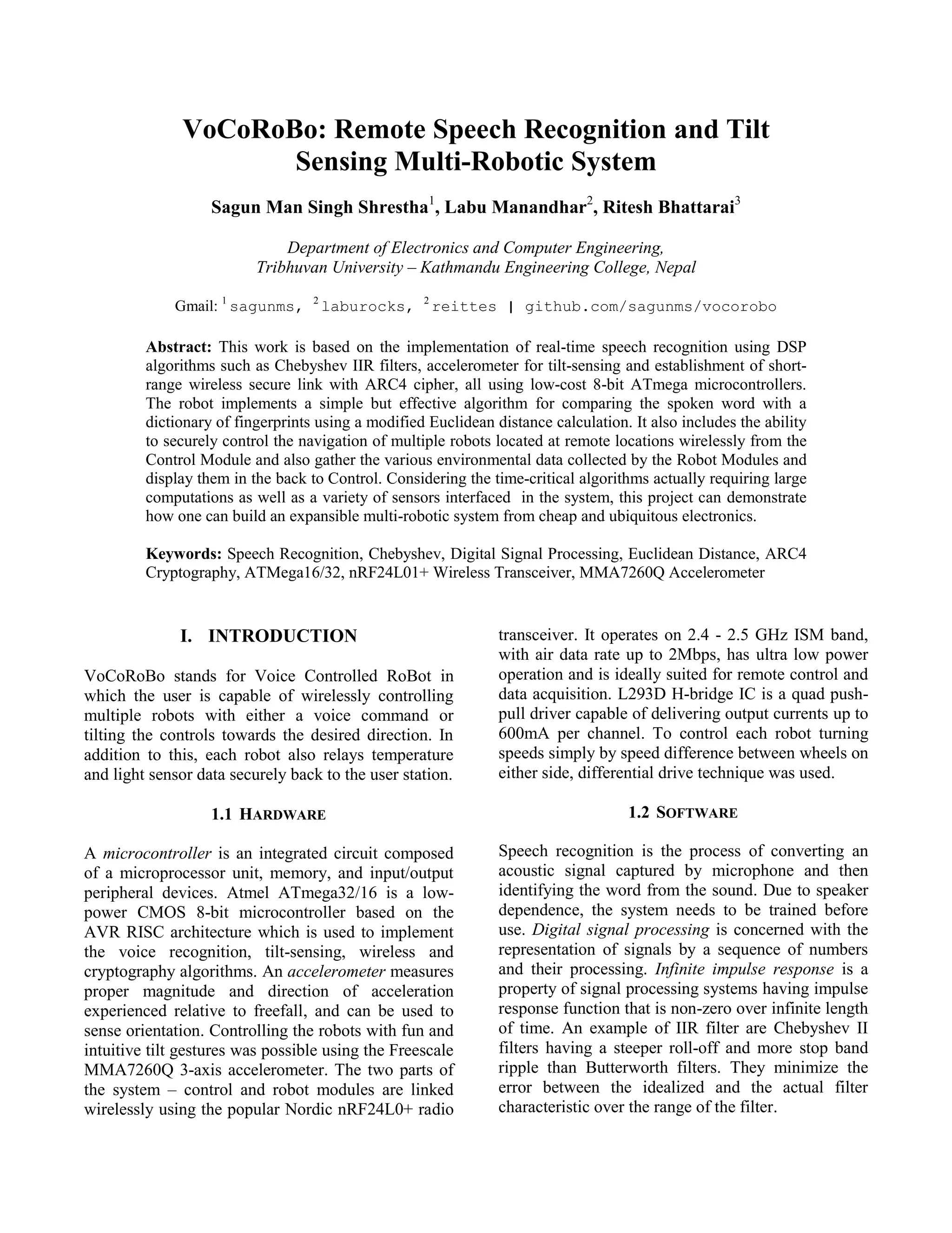
Figure 3.1: Overall Hardware Architecture
2.4 GHz
wireless link
with 2 bytes
(control byte
+ count byte)
payload
ATmega16 @ 8 MHz
(nRF24L01+ wireless
interface with ARC4
Cryptography)
ATmega32 @ 16 MHz
(Speech Recognition and
MMA7260Q Tilt
Sensing)
Port C
PB0-PB3
ADC
(Port A)
PD3-PD5
x y
z
Port C
SPI
(Port B)
PA0-PA2
nRF24L01
Module
LCD LEDs
Port C
SPI
(Port B)
PD0-PD3
LEDs
L293D
H-Bridge
M
M
nRF24L01
Module
ATmega16 @ 8 MHz
(nRF24L01+ with
ARC4 and H-Bridge
interface)](https://image.slidesharecdn.com/vocorobo-remotespeechrecognitionandtiltsensingmulti-roboticsytem-130707112759-phpapp02/75/VoCoRoBo-Remote-Speech-Recognition-and-Tilt-Sensing-Multi-Robotic-System-2-2048.jpg)
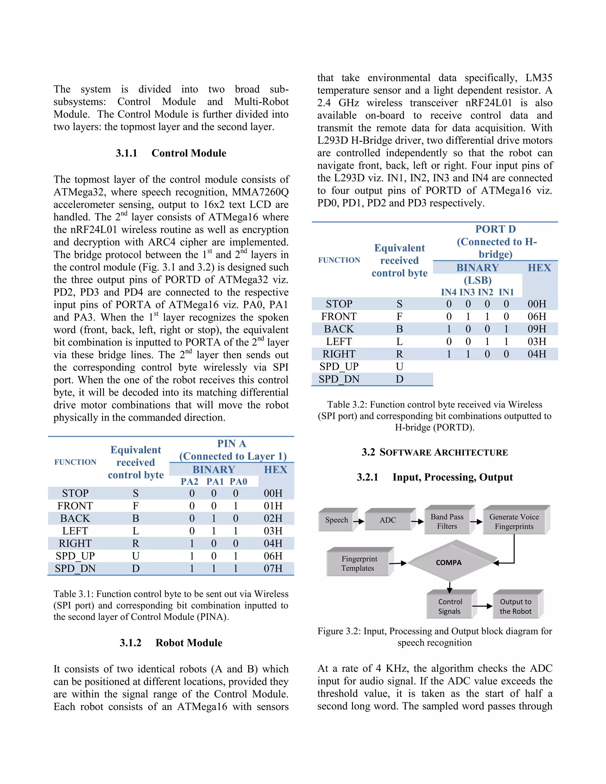
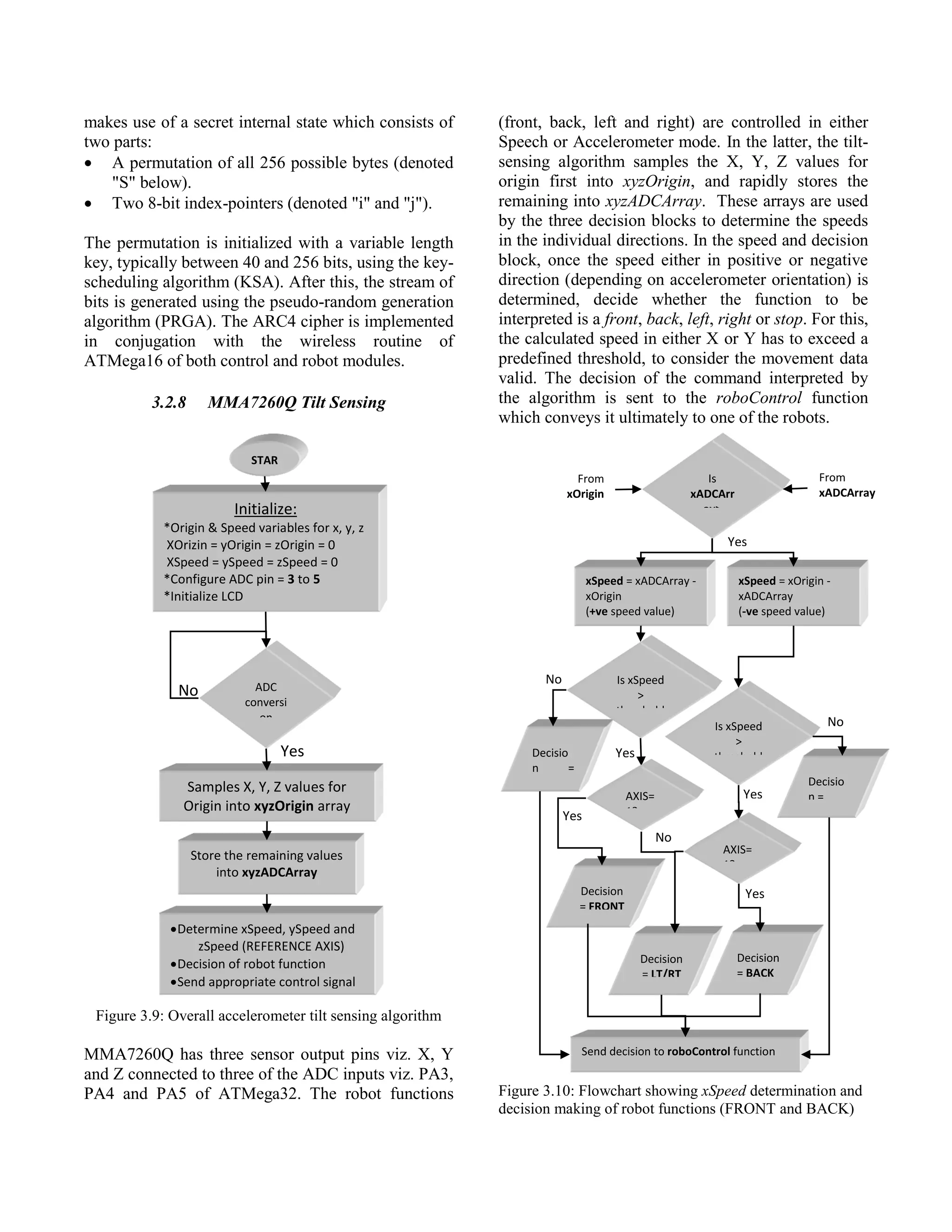
![The accuracy of the speech recognition was within an
acceptable range of above 90% by our initial
expectations of the system design. However,
considering the basic speech algorithm, recognition is
valid only for the same person who underwent the
preliminary voice training to initialize the dictionary
fingerprints. For convenience, the recorded voice of
Oxford dictionary software stored as a .wav file was
played in a relatively quiet surroundings.
4.5 Euclidean Distance Comparison
Figure 4.6: Euclidean Distance Comparison
UART logging from RealTerm was done and the
Euclidean distance comparison was logged with all
five different fingerprints already stored in the
EEPROM. As expected, the word was recognized as
the one with the least distance when comparing with
the five fingerprints.
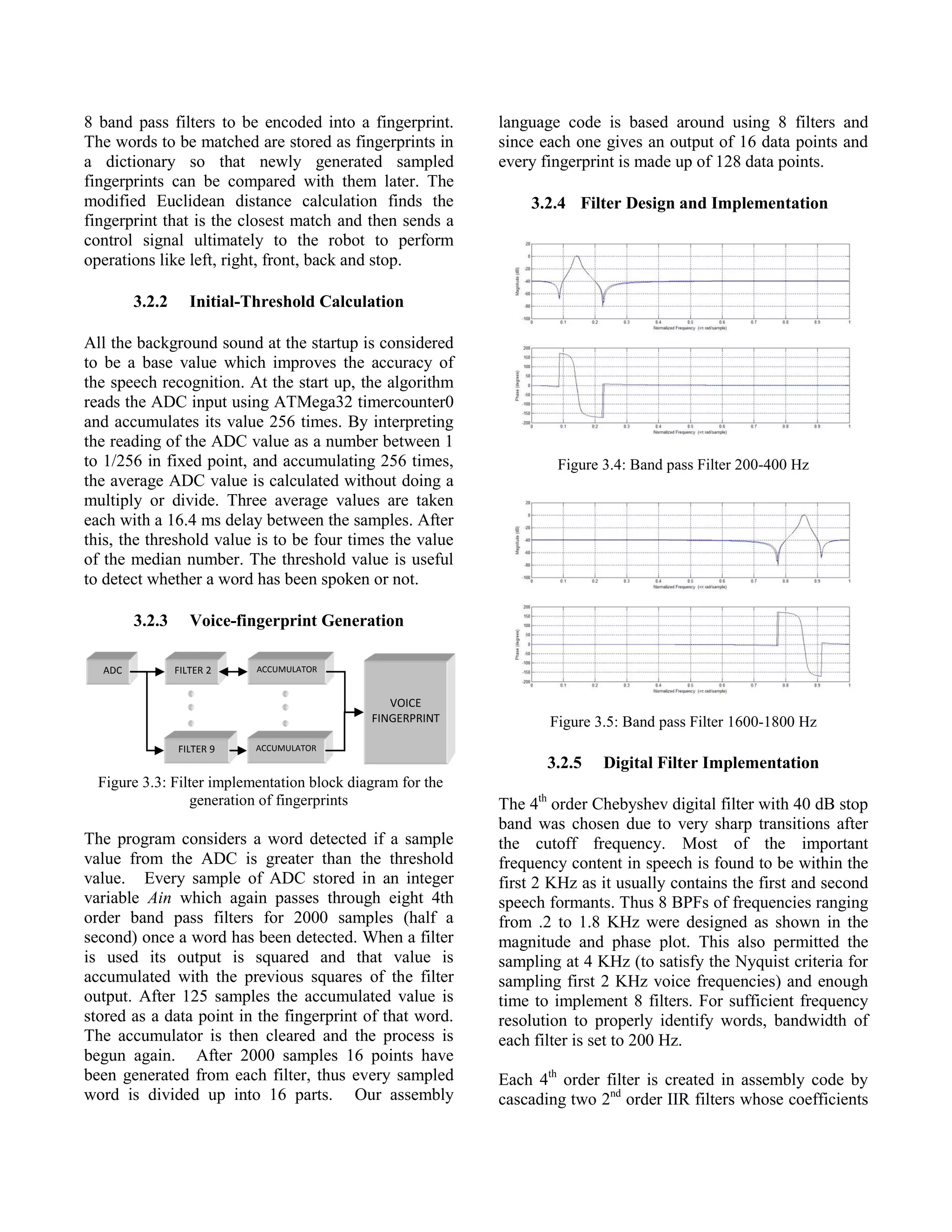
4.6 Wireless Transmit and Receive
4.6.1 Correct ARC4 Key Encryption/Decryption
The logged data data from the RealTerm is presented
below. It depicts correct ARC4 key encryption and
decryption. If the private key is matched in both the
control and robot modules as shown below, then the
encrypted data is decrypted back to the original data
as the PRGA of robot agent updates 12 times to catch
up with the PRGA of Control module.
CONTROL Initialized!
== Control Module ==
Private Key = SaGuN
- TX to Robot I -
Destination:
C2:C2:C2:C2:C2(Pipe1)
Original:
data_tx1[0]= S
data_tx1[1]=0
ROBOT Initialized!
== Robot Module I==
Private Key = SaGuN
-RX from Control-
Packet received!
Encrypted
data[0]= ‘
data[1]=0
No. of PRGA updates =
Encrypted:
data_tx1[0]= ‘
data_tx1[1]=0
Packet sent!
Current Sequence = 1
- TX to Robot I -
Destination:
C2:C2:C2:C2:C2(Pipe1)
Original:
data_tx1[0]= S
data_tx1[1]=1
Encrypted:
data_tx1[0]= ,
data_tx1[1]=1
Packet sent!
Current Sequence = 2
12 times
Decrypted
data[0]= S
data[1]=0
Current Sequence = 1
-RX from Control-
Packet received!
Encrypted
data[0]= ,
data[1]=1
Decrypted
data[0]= S
data[1]=1
Current Sequence = 2
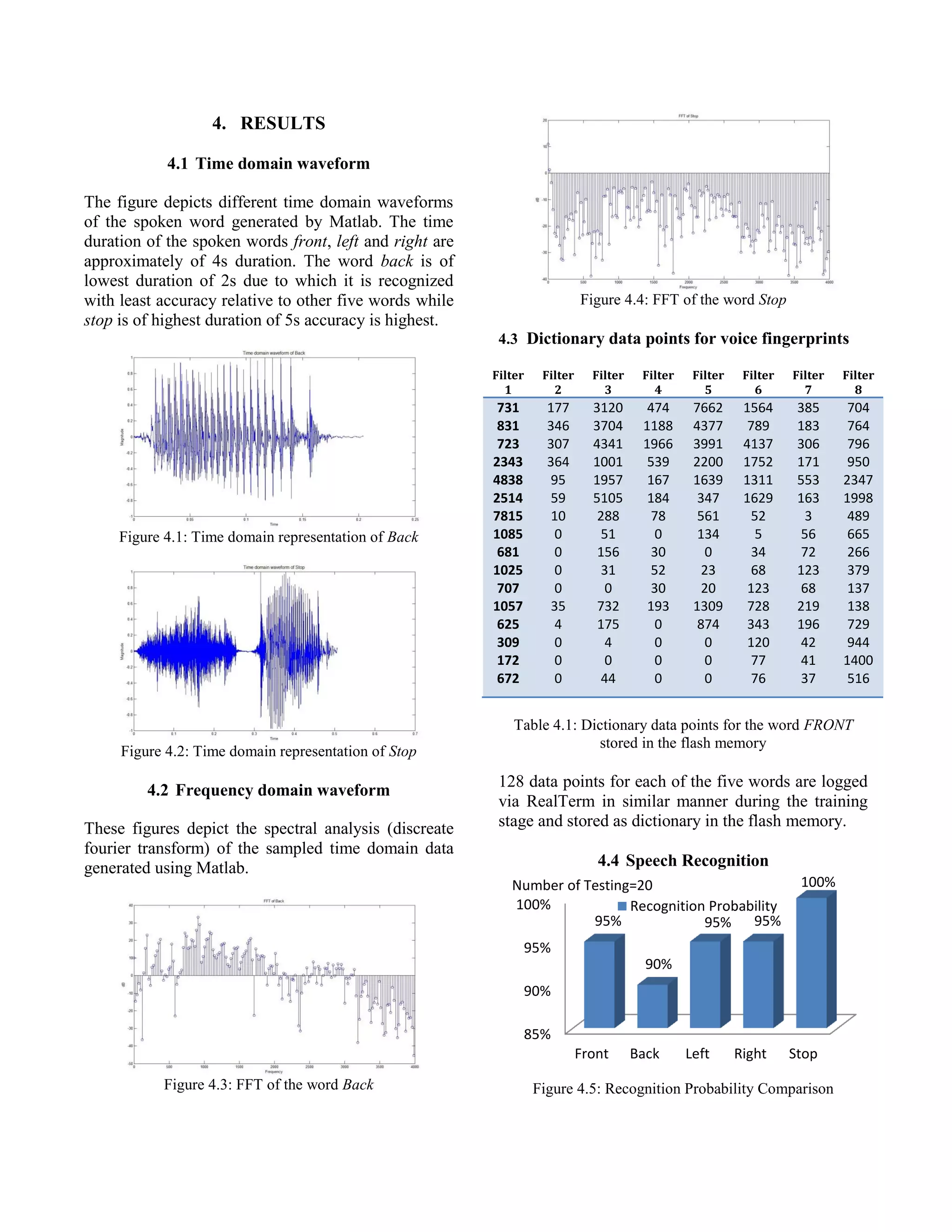
4.6.2 Incorrect ARC4 Key Encryption/Decryption
If the private key is not matched between the two
modules then the encrypted data cannot be decrypted
back to its original data as shown below.
CONTROL Initialized!
= Control Module =
Private Key= VoCoRoBo
- TX to Robot II -
Destination:
C2:C2:C2:C2:C3(Pipe2)
Original
data_tx1[0]= S
data_tx1[1]=0
Encrypted
data_tx1[0]= j
data_tx1[1]=0
Packet sent!
Current Sequence = 1
- TX to Robot II -
Destination:
C2:C2:C2:C2:C3(Pipe2)
Original
data_tx1[0]= S
data_tx1[1]=1
Encrypted
data_tx1[0]= D
data_tx1[1]=1
Packet sent!
Current Sequence = 2
ROBOT Initialized!
=Robot Module II=
Private Key = SaGuN
- RX from Control-
Packet received!
Encrypted
data[0]= j
data[1]=0
No. of PRGA updates =
7 times
Decrypted
data[0]= ƒ
data[1]=0
Current Sequence = 1
- RX from Control-
Packet received!
Encrypted
data[0]= D
data[1]=1
Decrypted
data[0]= ~
data[1]=1
Current Sequence = 2
5. CONCLUSION
This project is based on the implementation of real-
time speech recognition using DSP algorithms such
as Chebyshev IIR filters, accelerometer for tilt-
sensing and establishment of short-range wireless](https://image.slidesharecdn.com/vocorobo-remotespeechrecognitionandtiltsensingmulti-roboticsytem-130707112759-phpapp02/75/VoCoRoBo-Remote-Speech-Recognition-and-Tilt-Sensing-Multi-Robotic-System-9-2048.jpg)
![secure link with ARC4 cipher, all using ubiquitous
low-cost 8-bit microcontrollers. With an accuracy of
the speech recognition above 90%, it shows the
feasibility of the system to be applied in any low cost
applications in real time. It was observed that the
words with greater pronunciation stress were
recognized better. Although for now, the recognition
is accurate only for the same person who trained the
system, it can be expanded to make the system
speaker independent by further research on the
storing and retrieval of the voice fingerprint from a
different media. Multi-channel wireless link with
ARC4 was also successfully implemented to
exchange control and sensor data. As nRF24L01 is
capable of higher speed data transmission, the system
can also be expanded to incorporate other sensors
like audio or video sensors for richer data acquisition
.
6. REFERENCES
[1] T. Aamodt. (2003, April) “Speech Recognition
Algorithm”, University of British Columbia.
http://www.eecg.toronto.edu/%7Eaamodt/ece34
1/speech-recognition
[2] X. Lu, S. Lee, 2006. “Voice Recognition
Security System”, Cornell University
[3] A. Harison, C. Shah, 2006 "Voice Recognition
Car", Cornell University.
[4] B. R. Land; Cornell University; Fixed Point
mathematical function in GCC and assembler;
Optimized 2nd order IIR code.
[5] B. R. Land (2008, September). Fast Digital
Filtering. Circuit Cellar Issue # 218, p. 40.
[6] Application Note AVR201: “Using the AVR®
Hardware Multiplier”, Atmel Corporation.
[7] IIR Design: nauticom.net/www/jdtaft/iir.htm
[8] Brennen Ball; 2007; “Specializing in the NXP
LPC2148 and Microchip PIC18F452
microcontrollers and the Nordic Semiconductor
nRF24L01 2.4 GHz RF link”; diyembedded.com
[9] “Interfacing nRF2401 with SPI” (White Paper),
Nordic Semiconductor.
[10] T. Igoe, “MMA7260Q 3-Axis Accelerometer
Report for PIC 18F252 using PicBasic Pro”,
Sensor Workshop at ITP (January 16, 2006).
[11] Application Note AN3447: “Implementing Auto-
zero calibration technique for accelerometers”,
Freescale Semiconductors.
7. PICTURES
Figure 7.1: Overall System
Figure 7.2: Schematic Diagram of Control Module
Figure 7.3: Schematic Diagram of a single Robot Module](https://image.slidesharecdn.com/vocorobo-remotespeechrecognitionandtiltsensingmulti-roboticsytem-130707112759-phpapp02/75/VoCoRoBo-Remote-Speech-Recognition-and-Tilt-Sensing-Multi-Robotic-System-10-2048.jpg)

The document details the Vocorobo system, a multi-robotic setup using real-time speech recognition and tilt sensing, implemented with 8-bit Atmega microcontrollers and designed for cost-effectiveness and efficient operation. It features a speech recognition algorithm based on DSP techniques, secure wireless communication for navigation control, and sensor data transmission from robots to a user interface. The architecture includes two subsystems, a control module and robot module, utilizing hardware components such as accelerometers and wireless transceivers to enable intuitive control via voice commands and tilt gestures.


![Coded Agents – with UiPath SDK + LangGraph [Virtual Hands-on Workshop]](https://cdn.slidesharecdn.com/ss_thumbnails/codedagentsdeck-251215155422-5497c599-thumbnail.jpg?width=640&height=640&fit=bounds)


