This document describes the implementation of a SISO-OFDM transmission system using MATLAB and a TMS320C6713 digital signal processor (DSP). Key steps include:
1) Developing the baseband system model in Simulink with blocks for modulation, transmission over an AWGN channel, and demodulation.
2) Using Real-Time Workshop and the C6x Target to generate C code from the Simulink model and compile it for the TMS320C6713 DSP.
3) Deploying the system on TMS320C6713 DSP Starter Kits to perform real-time OFDM transmission and verify the implementation against simulations.
![Implementationof SISO-OFDM Transmissionusing MATLAB on DSP Processor
International Journal of Scientific Engineering and Technology Research
Volume.05, IssueNo.04, February-2016, Pages: 0676-0682
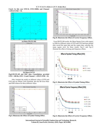
Fig.13. Code Composer Studio and hardware set up with
DSK 6713.
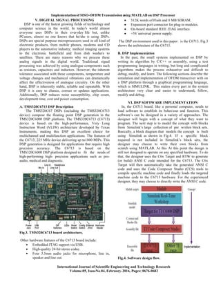
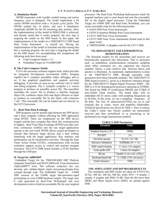
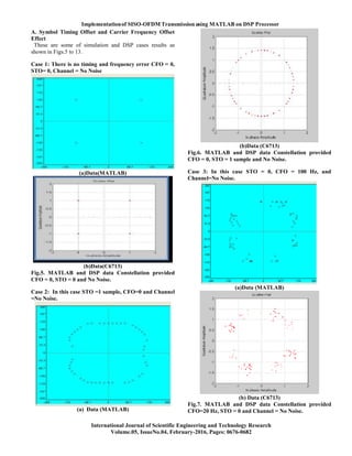
IX. CONCLUSION
Real time broadcast-like SISO-OFDM wireless transmission
on 5GHz employing TMS320C6713 DSP boards was
demonstrated. Baseband design was based on Simulink and
deployment was done on the C6713 DSP’s via automatic code
generation. Experimental measurements confirmed the
system’s specifications and typical results verified its
functionality and showed its potential for demonstrating
contemporary wireless communication concepts to students.
Thus the purpose of this simulator has achieved. It makes the
study of OFDM processing very easy.
X. REFERENCES
[1]P. Remlein, T. Cogalan and T. Gucluoglu, “OFDM with
Transmit and Receive Antenna Selection Based on Subcarrier
Groups”2010.
[2]Aida Zaier and Ridha Bouallègue, “A Full Performance
Analysis Of Channel Estimation Methods For Time Varying
OFDM Systems”2011.
[3]Anas A. Abu Tabaneh1, Abdulmonem H.Shaheen.
“MATLAB Simulation for Fixed Gain Amplify and Forward
MIMO Relaying System using OSTBC under Flat Fading
Rayleigh Channel”2011.
[4]Michael Dreschmann, Joachim Meyer Michael H¨ubner,
“Time and frequency synchronization for ultra-high speed
OFDM systems”2011.
[5]Navid Daryasafar and Ali Akbar Hashemi, “A Study Of
Channel Estimation Techniques With Carrier-Frequency
Offset Estimation In SISO-OFDM Systems”2012.
[6]Vishal Sharma and Sushank Chaudhary, “Implementation
of Hybrid OFDM-FSO Transmission System”2012.
[7]Nagarjuna.T and Ganesh.S , “Design And Development Of
Hybrid Adaptation Techniques In Mimo Ofdm System For
4G Wireless Networks”2013.
[8]Cong Luong Nguyen, Anissa Mokraoui, Pierre Duhamel,
Nguyen Linh-Trung. “Improved Time and Frequency
Synchronization Algorithm for 802.11a Wireless Standard
based on the SIGNAL Field”2013.
[9]P. Venkateswarlu, R. Nagendra. “Channel Estimation
Techniques in MIMO-OFDM LTE Systems”2014.
[10]Edem Thesis ,” OFDM Modulation Technique And ROF
System, Design-Principle Of Operations.
[11]Vol.Yong Soo Cho, Jaekon Kim And Won Young Yang,
“MIMO-OFDM Wireless Communication With MATLAB”.
Vol.](https://image.slidesharecdn.com/326451ijsetr8768-122-231226083125-aad721f9/85/Implementation-of-SISO-OFDM-Transmission-using-MATLAB-on-DSP-Processor-7-320.jpg)