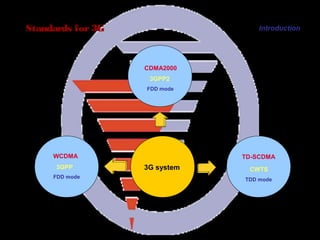
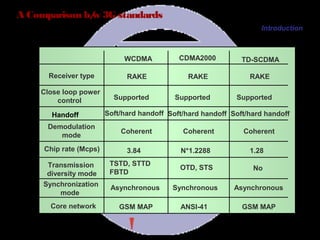
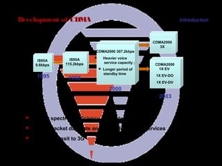
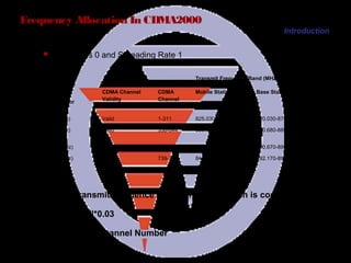
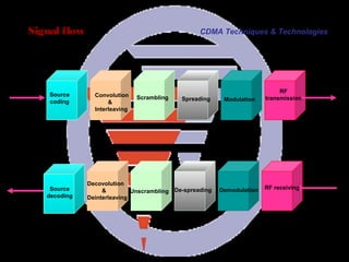
the development of mobile communication system
the structure of CDMA2000 network
the number planning in CDMA2000 network
the techniques used by CDMA system including:
source coding, channel coding, interleaving, scrambling, spreading and modulation etc.
power control, soft handoff, RAKE receiver
F-PCH,F-PICH,F-SYNCH,F-FCH,F-SCH,R-ACH,R-PICH
Long code, short code and Walsh code
Chapter 1: Introduction
Chapter 2: CDMA Techniques & Technologies
Chapter 3: CDMA Air Interface
Chapter 4: CDMA Number Planning
– There are others : IS95 HDR, EDGE, etc.
» Direct Spread CDMA TDD
» Direct Spread CDMA FDD
» Multi-carrier CDMA FDD
Global 3G comprises of 3 modes :
– Marketed as Global 3G CDMA implying a single unified standard. In reality,
– Mostly dominated by Direct Sequence CDMA.
– Market is expected to be fragmented amongst several competing
IMT2000 guidelines defined by the ITU.
– Analog was 1G. GSM/IS95 were 2G. Next is 3G.
What is 3G ?
standards.
across the world.
Envisioned as a single Global standard allowing seamless roaming
Used interchangeably with IMT2000 although there are some specific
A loosely defined term referring to next generation wireless systems.
1: Direct sequence and frequency hopped spread spectrum, spreading sequence and their correlation functions, Acquisition and tracking of spread spectrum signals.
2: Error probability for DS-CDMA, on AWGN channels, DS-CDMA on frequency selective fading, channels, Performance analysis of cellular CDMA.
3: Capacity estimation, Power control, effect of imperfect power control on DS CDMA performance, Soft Handoffs.
4: Spreading /coding tradeoffs, multi-carrier CDMA, IS-95 CDMA system, third generation CDMA systems, multi-user detection.
Definition:WiMAX is a fourth generation (4G) technology.WiMAX stands for Worldwide Interoperability for Microwave Access.WiMAX is technically also known as “IEEE 802.16”WiMAX is a wireless communications standard designed for creating Metropolitan Area Networks(MANs).A Broadband Wireless Access(BWA) technique offering fast broadband connection.It allows a user, to browse the internet on a laptop without physically connecting it to a router.It involves microwaves for the transfer of data wirelessly.Founded by Ensemble, CrossSpan, Harris & Nokia.
Introduction
Channel Configuration
Idle Mode Operation
Protocols
Radio resources
Measurements
Power Control
HO process
Intelligent Underlay Overlay
Handover Support for Coverage Enhanchements
The extended cell
Dynamic Hotspot
Dual band GSM/DCS Network Operation
Half Rate
HSCSD
4
encompasses three optional modes of operation.”
Telecommunications Union (ITU) of a single CDMA third generation standard that
“Qualcomm and Ericsson ... jointly support approval by the International
Jun 1999 found compromise at the OHG.
“Qualcomm … is not prepared to grant licences according to the … ETSI IPR Policy.”
fair, reasonable and non-discriminatory basis in accordance with the ... ETSI IPR Policy.”
“Ericsson … is prepared to grant licences to these [W-CDMA & TD-CDMA] patents on
Dec 1998 saw a stand-off in standards.
WCDMA, WTDMA, OFDMA, Global CDMA 1 & 2.
Asia Pacific (ARIB & TTA):
WCDMA N/A, UWC-136, cdma2000, WIMS WCDMA, WP-CDMA.
North America(T1P1, TR45.3, TR45.5, TR46.1):
WCDMA, WTDMA,TDMA/CDMA, OFDMA, ODMA.
Europe (ETSI):
In
n
scrambling achieve?
scrambling achieve?
6
Secure link: a linear sequence of length 2
doesn’t
Benefits of wideband signals: multipath provides temporal diversity instead of ISI.
Spectral re-use factor of 1: all cells can use the same frequency spectrum.
does
What
What
Low cross-correlation (at any time offset).
High auto-correlation (at any time offset).
What are their important properties?
in to a low amplitude, wide bandwidth signal.
Converts a high amplitude, narrow bandwidth signal
How do they work?
Pseudo-random sequences: Gold codes, Kasami codes (M-sequences).
‘W’ of WCDMA.
W
The GSM standard was developed by the Groupe SpecialMobile, which was an initiative of the Conference of European Post and Telecommunications (CEPT) administrations.
The responsibility for GSM standardization now resides with the
Special Mobile Group (SMG) under the European Telecommunication Standard Institute (ETSI).
Fully digital system utilizing the 900MHz frequency band.
TDMA over radiocarriers(200 kHz carrier spacing)
8 full rate or 16 half rate TDMA channels per carrier
User/terminal authentication for fraud control
Encryption of speech and data transmissions over the radio path
Full international roaming capability
Low speed data services (upto 9.6kb/s)
Compatibility with ISDN for supplementary services
Support of short message services(SMS)
GSM supports a range of basic and supplementary services, and these services are defined analogous to those for ISDN(i.e.,bearer services, teleservices, and supplementary services).
The most important service supported by GSM is Telephony.
Other services derived from telephony included in the GSM specification are emergency calling and voice messaging.
Bearer services supported in GSM include various asynchronous and synchronous data services for information transfer.
Teleservices based on these bearer services include group 3 fax and short message service(SMS)
The data capabilities of GSM have now been enhanced to include high speed circiut-switched data(HSCSD) and general packet radio service (GPRS).
Call offering services call forwarding
Call resrtiction services call barring
Call waiting service
Call hold service
Multi party service tele conferencing
Calling line presentation restriction services
Advice of charge service
Closed user group service
The GSM System comprises of Base Transceiver Station (BTS), Base Station Controllers (BSC), Mobile Switching Centers (MSC), and set of registers (databases) to assist in mobility management and security functions.
All signaling between the MSC and the various registers (databases) as well as between the MSCs takes place using the Signaling System 7(SS7) network, with the application level messages using the Mobile Application Protocol (MAP) designed specifically for GSM.
The MAP protocol utilizes the lower layer functions from the SS7 protocol stack.
It is required that after the course study
you should:
Have a general concept about DT
Master Panorama DT operation
Master Panorama data analysis
Chapter 1 DT Introduction
Chapter 2 Panorama DT Introduction
Chapter 3 Panorama DT Data Analysis
Collect System Air interface data
Analyze Air interface data
Assist Export Analysis report
Qualcom CAIT
CDMA Air Interface Tester
WILL TECH DM2K/Pecker
Pecker Navigator, Pecker Analyzer
Panorama
Qualcom CAIT
CDMA Air Interface Tester
WILL TECH DM2K/Pecker
Pecker Navigator, Pecker Analyzer
Panorama
C cf radio propagation theory and propagation modelsTempus Telcosys
The radio propagation theory is an important lesson in the radio communication curriculum. This lesson answers the following questions:
How are radio waves transmitted from one antenna to the other antenna?
What features does the radio wave have during the propagation? Which factors affect the propagation distance?
What fruits are achieved by predecessors in the radio wave propagation theory? How to apply the theory to practice?
Chapter 1 Radio Propagation Theory
Chapter 2 Radio Propagation Environment
Chapter 3 Radio Propagation Models
FREQUENCY CONCEPTS
The following table summarizes the frequency-related specifications of each of the GSM systems. The terms used in the table are explained in the remainder of this section.
System P-GSM 900 E-GSM 900 GSM 1800
Frequencies: • Uplink • Downlink
890-915 MHz
935-960 MHz
Wavelength ~ 33 cm
880-915 MHz
925-960 MHz
GSM 1900
1710-1785 MHz
1805-1880 MHz
1850-1910 MHz
1930-1990 MHz
~ 33 cm ~ 17 cm ~ 16 cm
Bandwidth 25 MHz
35 MHz 75 MHz 60 MHz
Duplex Distance 45 MHz
45 MHz 95 MHz 80 MHz
Carrier Separation 200 kHz
1
Radio Channels
200 kHz 200 kHz 200 kHz
125
175 375 300
Transmission Rate 270 kbits/s
270 kbits/s 270 kbits/s 270 kbits/s
Table 3-1 Frequency-related specifications
FREQUENCY
F Did you know?
Due to frequency, a BTS transmitting information at 1800 MHz with an output power of 10 Watts (W) will cover only half the area of a similar BTS transmitting at 900 MHz. To counteract this, BTSs using 1800 MHz may use a higher output power.
An MS communicates with a BTS by transmitting or receiving radio waves, which consist of electromagnetic energy. The frequency of a radio wave is the number of times that the wave oscillates per second. Frequency is measured in Hertz (Hz), where 1 Hz indicates one oscillation per second. Radio frequencies are used for many applications in the world today. Some common uses include:
• Television: 300 MHz approx. • FM Radio: 100 MHz approx. • Police radios: Country dependent • Mobile networks: 300 - 2000 MHz approx.
The frequencies used by mobile networks varies according to the standard being used
2
. An operator applies for the available frequencies or, as in the United States, the operator bids for frequency bands at an auction. The following diagram displays the frequencies used by the major mobile standards:
DAMPS 1900 MHz
0450900800 1500 1800 1900 NMT 450
PDC 800
GSM 900 GSM 1800 GSM 1900NMT 900
PDC 1500AMPS DAMPS 800
TACS
Figure 3-1 Frequencies for major mobile standards
International Journal of Engineering Research and Applications (IJERA) is an open access online peer reviewed international journal that publishes research and review articles in the fields of Computer Science, Neural Networks, Electrical Engineering, Software Engineering, Information Technology, Mechanical Engineering, Chemical Engineering, Plastic Engineering, Food Technology, Textile Engineering, Nano Technology & science, Power Electronics, Electronics & Communication Engineering, Computational mathematics, Image processing, Civil Engineering, Structural Engineering, Environmental Engineering, VLSI Testing & Low Power VLSI Design etc.
PERFORMANCE ANALYSIS OF QOS PARAMETERS LIKE PSNR, MAE & RMSE USED IN IMAGE TR...Journal For Research
Wireless designers constantly seek to improve the spectrum efficiency/capacity, coverage of wireless networks and link reliability. In this direction, Space-time wireless technology that uses multiple antennas along with appropriate signaling and receiver techniques that offers a powerful tool for improving the wireless performance is used in this thesis work. A special version of STBC called ‘Alamouti code’ is used. PSK modulation scheme is used for modulation of data. In this thesis work, the Space-Time Block Codes (STBC) is used in WLAN wireless network that uses multiple numbers of antennas at both transmitter and receiver. The STBC which includes the Alamouti Scheme for 2 transmit antenna and a different number of receiving antenna has been studied, simulated and analyzed. The simulation has been done in MATLAB. Throughput and several parameter performance has been analyzed using the MATLAB.A sample image is transmitted to compare the performance of various parameters like RMSE, PSNR, MAE etc. All the parameters are plotted against SNR (in dB) values ranging from -18 to 30. Various observations being made for the improvement in various parameters with increasing SNR and/or with changing diversity scheme. AWGN channel is used here for communication of sampled image data.
International Journal of Engineering Research and Applications (IJERA) is an open access online peer reviewed international journal that publishes research and review articles in the fields of Computer Science, Neural Networks, Electrical Engineering, Software Engineering, Information Technology, Mechanical Engineering, Chemical Engineering, Plastic Engineering, Food Technology, Textile Engineering, Nano Technology & science, Power Electronics, Electronics & Communication Engineering, Computational mathematics, Image processing, Civil Engineering, Structural Engineering, Environmental Engineering, VLSI Testing & Low Power VLSI Design etc.
Dear students get fully solved assignments
Send your semester & Specialization name to our mail id :
“ help.mbaassignments@gmail.com ”
or
Call us at : 08263069601
Basic Telecom concepts
Various Wireless Technologies
Cellular concepts & Principal of cellular Comm.
GSM Network Architecture
GSM channel Architecture
Call Flows in GSM
GSM Planning steps (Nominal Plan & RF surveys)
Alternative means of wireless communication
Walkie - Talkie
Pagers
Trunked private radios
Mobile Phone - the magic technology that enables everyone to communicate anywhere with anybody.
Till 1982 Cellular Systems were exclusively Analog Radio Technology.
Advanced Mobile Phone Service (AMPS)
U.S. standard on the 800 MHz Band
Total Access Communication System (TACS)
U.K. standard on 900 MHz band
Nordic Mobile Telephone System (NMT)
Scandinavian standard on the 450 & 900 MHz band
Full rate => Used for speech at 13 Kbits/s
or sending data at 9.6 Kbits/s
Half rate => Used for speech at 6.5 Kbits/s
or sending data at 4.8 Kbits/s
Enhanced Full rate => Used for speech at 13 Kbits/s
or sending data at 9.6 Kbits/s but
with almost Land line quality
FCCH = FREQUENCY CORRECTION CHANNEL
=> To tell the Mobile that this is the BCCH carrier
=> To able the Mobile to synchronize to the frequency
(Downlink only)
SCH = SYNCHRONISATION CHANNEL
=> Used for sending BSIC (Base station Identity Code)
=> Give TDMA frame number to the Mobile.
(Downlink only)
BCCH = BROADCAST CONTROL CHANNEL
=> Used for sending information to the mobile like
CGI (Cell Global identity), LAI (Location Area Identity),
BCCH carriers of the neighboring cells,
maximum output power allowed in the cell and other
broadcast messages like barred cell. (Downlink only)
PCH = PAGING CHANNEL
=> Used for paging the Mobile. (Downlink only)
Reason could be an incoming call or an incoming Short Message.
RACH = RANDOM ACCESS CHANNEL
=> Used for responding to the paging (terminating), Location updating
or to make call access (originating) by asking for a signaling channel.
(Uplink only)
AGCH = ACCESS GRANT CHANNEL
=> Used to allocate SDCCH to the mobile.
(Downlink only)
ell Allocation (CA) is the subset of the total frequency band that is available for one BTS. It can be viewed as the total transport resource available for traffic between the BTS and its attached MSs. One Radio Frequency CHannel (RFCH) of the CA is used to carry synchronization information and the Broadcast Control CHannel (BCCH). This can be any of the carriers in the cell and it is known as the BCCH carrier or the c
carrier. Strong efficiency and quality requirements have resulted in a
0
rather complex way of utilizing the frequency resource. This chapter describes the basic principles of how to use this resource from the physical resource itself to the information transport service offered by the BTS.
Carrier separation is 200 kHz, which provides: • 124 pairs of carriers in the GSM 900 band • 374 pairs of carriers in the GSM 1800 band • 299 pairs of carriers in the GSM 1900 band
Using Time Division Multiple Access (TDMA) each of these carriers is divided into eight Time Slots (TS). One TS on a TDMA frame is called a physical channel, i.e. on each duplex pair of carriers there are eight physical channels.
A variety of information is transmitted between the BTS and thMS. The information is grouped into different logical channelsEach logical channel is used for a specific purpose such as paging, call set-up and speech. For example, speech is sent on the logical channel Traffic CHannel (TCH). The logical channels are mapped onto the physical channels.
The information in this chapter does not include channels specific for GPRS (General Packet Radio Service). For basic information on GPRS see chapter 14 of this documentation.
Common core mechanics in Nokia UltraSite EDGE BTS Outdoor and Nokia UltraSite EDGE BTS Indoor
Common plug-in units
1940 x 770 x 750 mm (H x W x D)
Identical footprint to CityTalk BTS
Weight
Max weight (12 TRX) 340 kg
Heaviest single part 58 kg (core mechanics)
Heaviest plug-in unit 18 kg (RTC)
Acoustic noise (max): 68 dB(A)
Climatic conditions:
w/o heater -10°C ... +50°C
with optional heater -33°C ... +50°C
Ingress Protection Class: IP 55
Two level environmental protection:
BTS core and cabinet door provides EMC shielding
Outdoor kit provides additional weather proofing
The GENEX Assistant is excellent software tool for
Post-Processing 2G & 3G Drive Test Data.
With the GENEXAssistant, you can:
Have a panorama view of network performance
Locate network troubles
Improve network quality
Verify network planning and optimization
ANALYSIS OF LOGFILE
FOR POST PROCESSING OF LOGFILE IN
GENEX ASSISTANCE WE NEED TO
OPEN A NEW PROJECT
. Overview
2. Handover Causes & Priorities
3. Threshold Comparison Process
4. Target Cell Evaluation Process
5. Handover Algorithms
Power Budget (PBGT)
Level & Quality (RXLEV & RXQUAL)
Umbrella (& Combined Umbrella/PBGT)
MS Speed (FMMS & MS_SPEED_DETECTION)
6. Imperative Handovers
Distance
Rapid Field Drop (RFD) & Enhanced Rapid Field Drop (ERFD)
7. Handover Timers
Call continuity - to ensure a call can be maintained as a MS moves geographical location from the coverage area of one cell to another
Call quality - to ensure that if an MS moves into a poor quality/coverage area the call can be moved from the serving cell to a neighbouring cell (with better quality) without dropping the call
Traffic Reasons - to ensure that the traffic within the network is optimally
distributed between the different layers/bands of a network
If 2 or more handover (PC) criteria are satisfied simultaneously the following priority list
is used in determining which process is performed;
. Uplink and downlink Interference
2. Uplink quality
3. Downlink quality
4. Uplink level
5. Downlink level
6. Distance
7. Enhanced (RFD)
8. Rapid Field Drop (RFD)
9. Slow moving MS
10. Better cell i.e. Periodic check (Power Budget HO or Umbrella HO)
11. PC: Lower quality/level thresholds (UL/DL)
12. PC: Upper quality/level thresholds (UL/DL)
Transmission management in BSS is a feature used in managing the Base Station Subsystem transmission system functions such as supervision, alarms, statistics
and settings. The network element mainly responsible for transmission management in BSS is the Base Station Controller (BSC).
Transmission management functionalities make it possible for the operators to manage the transmission equipment remotely from the BSC or from Nokia
NetAct integrated network management system, which simplifies network maintenance and operation. Supervision functions help minimise the time spent in maintenance, and statistics collection helps the operators analyse and optimise
the use of their transmission equipment. Moreover, new software can be downloaded in a way that does not interfere with the traffic.
Hardware and software requirements BSS transmission network elements
BSS transmission management functionalities Transmission parameters Transmission alarms
Transmission measurements
2.Hardware and software requirements
There are no specific hardware or software requirements for the transmission management functionalities. However, the type of the BTS poses certain
limitations.
The BTS type specific functionalities are listed in the table below.
More details about the functionalities can be found in BSS transmission management functionalities .
Polling list sending with priority is a functionality used in positioning. To ensure accurate positioning calculations, the LMU unit must supply Radio Interface Timing System (RIT) information to the network faster than the normal Q1 polling is able to do. Faster LMU polling is achieved by defining a Q1 polling
priority for each Q1 device, with the LMU having the highest priority. For more information see Location Services .
3.BSS transmission network elements
The base Station Subsystem (BSS) consists of at least one Base Station Controller (BSC) and its Base Transceiver Stations (BTS). The Transcoder Submultiplexer
(TCSM) is also part of the BSS although it is actually located in the MSC site. The three basic configurations (topologies) for transmission between the BSC and
the BTSs are: point-to-point connection
multidrop chain multidrop loop
In point-to-point configuration each BTS is connected directly to the BSC. In the multidrop chain, BTSs form a chain and the first BTS in the network is connected directly to the BSC. In the loop connection, the BTSs form a loop where the first and the last BTS in the loop are connected directly to the BSC via a crossconnecting node. The topology used depends on a number of factors such as the distance between the BSC and the BTS, the number of transceivers (TRXs) used at a particular BTS site and the signalling channel rate between the BSC and the\ BTS. Usually the topology used is a mixture of the three basic topologies. Formore information on the topologies, refer to Nokia BSS Transmission\Configuration .
Cdma2000 network problem analysis with mobile station 20030212-a-v1.0Tempus Telcosys
Keyword: CDMA, forward coverage, reverse coverage and connection
Abstract: This document describes how to use a Mobile Station (MS) to locate network problems. That is, judge the forward/reverse coverage by viewing the indices displayed on the Debug screen of MS. Then locate the network problems according to reverse Frame Error Rate (FER) and Received Signal Strength Indicator (RSSI) test on the background. This document uses H100 MS as an example for the description. For settings of other CDMA MSs, see the relevant document.
1.1
Displaying Debug Screen of H100 MS
1.2
1) 2) 3) 4)
Switch on the MS; Input password: ##27732726; Press the red Power-off key; Select 3.
The Debug screen is displayed.
Index Value on Debug Screen
Assume that the following information is displayed on the Debug screen:
P232 R085 C0210
03612-00001-1
PAGE Ec: -5.0
RX: -75 TX: NoTx
P232: PN of primary service sector
C0210: System operating frequency
03612: SID
00001: NID
PAGE: Channel mode
Ec: Ec/Io
Rx: Receive level of MS
TX: Transmit level of MS
Thou
QCTest™ CDMA Air Interface Tester (CAIT™) 3.1 User’s GuideTempus Telcosys
QUALCOMM Proprietary
Export of this technology or software is regulated by the U.S. Government. Diversion contrary to Ulaw prohibited.
All data and information contained in or disclosed by this document are confidential and proprietinformation of QUALCOMM Incorporated, and all rights therein are expressly reserved. By acceptthis material, the recipient agrees that this material and the information contained therein are heldconfidence and in trust and will not be used, copied, reproduced in whole or in part, nor its contentsrevealed in any manner to others without the express written permission of QUALCOMM Incorporated.
Mobile communications is one of the communications fields that develop rapidly and energetically. The antenna builds the bridge between user terminals and base control devices. It is widely used in the mobile communications and the wireless access communication system. The rapid development of the antenna greatly promotes its technology innovation.
It is important to deeply grasp the knowledge of the antenna, which is useful to:
Install and maintain products.
Promote the network planning.
Chapter 1 Working Principle
Chapter 2 Classification
Chapter 3 Electrical Index
Chapter 4 Mechanical Index
When the conducting cable carries the alternating current, the electromagnetic wave radiation can be formed.
If two conducting cables are close, the directions of their current are opposite, and the electromotive force is counteracted. Thus the radiation becomes week.
If two conducting cables are open, the directions of their current are the same. Thus the radiation becomes strong.
When the length of the conducting cable is like the wavelength, the current on the cable will be enhanced. Thus the radiation becomes strong.
The straight conducting cable which can generate the strong radiation is called the dipole.
The pole whose two arms are of the same length (1/4 Wavelength) is called as dipole or half-wave-length dipole.
What is Handoff in mobile network?
What is the Search Window?
How to optimize handoff parameters?
Upon completion of this course, you will be able to:
Know handoff principle and classification.
Know search window and key parameters.
Master handoff tuning in network.
Chapter 1 Basic Concept
Chapter 2 Handoff in CDMA
Chapter 3 Optimization Command
Chapter 4 Summary
Soft handoff
It is a process of establishing a link with a target sector before breaking the link with the serving sector.
Softer handoff
Similar to the soft handoff, but the softer handoff is occurred among multi-sectors in the same base station.
Hard handoff
Hard handoff occurs when the two sectors are not synchronized or are not on the same frequency. Interruption in voice or data communication occurs but this interruption does not effect the user communication.
CDMA soft handoff is driven by the handset
Handset continuously checks available pilots
Handset tells system pilots it currently sees
System assigns sectors (up to 6 max.), tells handset
Handset assigns its fingers accordingly
All messages sent by dim-and-burst, no muting!
Each end of the link chooses what works best, on a frame-by-frame basis!
Users are totally unaware of handoff
CDMA 1x Introduction to Power Control Issue2.1Tempus Telcosys
One of the aims of the CDMA1X system is to maximize the number of its users. If each mobile station (MS) adjusts its transmitter power to minimize the signal noise received by the base transceiver station (BTS), the capacity of the system is maximized. Higher power brings higher interference and results in more capacity loss. Power control can adjust the transmission power of the MS and BTS, aiming to minimize the interference
After learning this course, you will learn the following:
The importance of the power control of the CDMA system
Categories and calculating theories of the power control
Data configuration of the power control
Chapter 1 Goals and Principles of Power Control
Chapter 2 Categories and Arithmetic of Power Control
Chapter 3 Data Configuration of Power Control
Each couple of customers is in a same room.
Each couple of customers speaks a language different from that spoken by other couples.
If the noise becomes louder, all the customers will raise their voices.
If the noise is too louder, the customers may go to other rooms.
The customer who speaks too loudly will affect the communication of others.
The transmission power of the control BTS and MS must ensure that the signal sent to the receiver through the complicated radio space can meet the threshold of correct demodulation.
When the first principle is satisfied, the transmission power of the BTS and MS is required to be lowered as much as possible to decrease the interference between users and best optimize the network performance.
The transmission power of the MS near the BTS is lower than that of the MS far from the BTS and of the MS in the fading areas.
Electrical properties
Operation Frequency Band
Input impedance
VSWR
Polarization
Gain
Radiation Pattern
Horizontal/Vertical beamwidth
Downtilt
Front/back ratio
Sidelobe suppression and null filling
Power capability
3rd order Intermodulation
Insulation
Mechanical properties
Size
Weight
Radome material
Appearance and color
Working temperature
Storage termperature
Windload
Connector types
Package Size
Lightening
TRANSMISSION :
A PROCESS WHERE TRAFFIC (VOICE,DATA,VIDEO) IS DESPATCHED OVER A MEDIUM BETWEEN THE SOURCE AND THE DESTINATION
TYPES OF TRANSMISSION MEDIA :
WIRED TRANSMISSION MEDIA
1.COPPER CABLE
2.OPTICAL FIBER
WIRELESS TRANSMISSION MEDIA
1.VSAT NETWORKS
2.MICROWAVE RADIO
Possible media for communication
Introduction to Communication Media
Introduction to Microwave communication
Manufacturers of Microwave
Why Microwave?
Characteristics of microwave
Types of Microwave communication
Types of Microwave Links
Requirements for the microwave communication
What is LOS?
Wave Propagation in the atmosphere
Multi path Propagation
LOS Purpose & requirements
Limitations of Line of Sight Systems
Design of Line of Sight Microwave Links
K- factor
Variations of the ray curvature as a function of k
Fresnel zone
Obstacles & Loses
Knife Edge Obstacles
Smooth Spherical Earth Obstacles
Path Loss
Other losses
Why vertical polarization favorable at high freq
Antenna type & Gain
RECEIVER SENSITIVITY, FADE MARGIN AND SIGNAL TO NOISE RATIO
Fading Margin
Reliability
Instruction to MAPINFO
This course is intended to give a brief introduction to MAPINFO on the following aspects:
To get a knowledge of basic functions of MAPINFO and be familiar with normal operations of MAPINFO
To carry out network planning, optimization and map maintenance with MAPINFO
Safalta Digital marketing institute in Noida, provide complete applications that encompass a huge range of virtual advertising and marketing additives, which includes search engine optimization, virtual communication advertising, pay-per-click on marketing, content material advertising, internet analytics, and greater. These university courses are designed for students who possess a comprehensive understanding of virtual marketing strategies and attributes.Safalta Digital Marketing Institute in Noida is a first choice for young individuals or students who are looking to start their careers in the field of digital advertising. The institute gives specialized courses designed and certification.
for beginners, providing thorough training in areas such as SEO, digital communication marketing, and PPC training in Noida. After finishing the program, students receive the certifications recognised by top different universitie, setting a strong foundation for a successful career in digital marketing.
Read| The latest issue of The Challenger is here! We are thrilled to announce that our school paper has qualified for the NATIONAL SCHOOLS PRESS CONFERENCE (NSPC) 2024. Thank you for your unwavering support and trust. Dive into the stories that made us stand out!
Executive Directors Chat Leveraging AI for Diversity, Equity, and InclusionTechSoup
Let’s explore the intersection of technology and equity in the final session of our DEI series. Discover how AI tools, like ChatGPT, can be used to support and enhance your nonprofit's DEI initiatives. Participants will gain insights into practical AI applications and get tips for leveraging technology to advance their DEI goals.
Exploiting Artificial Intelligence for Empowering Researchers and Faculty, In...Dr. Vinod Kumar Kanvaria
Exploiting Artificial Intelligence for Empowering Researchers and Faculty,
International FDP on Fundamentals of Research in Social Sciences
at Integral University, Lucknow, 06.06.2024
By Dr. Vinod Kumar Kanvaria
Biological screening of herbal drugs: Introduction and Need for
Phyto-Pharmacological Screening, New Strategies for evaluating
Natural Products, In vitro evaluation techniques for Antioxidants, Antimicrobial and Anticancer drugs. In vivo evaluation techniques
for Anti-inflammatory, Antiulcer, Anticancer, Wound healing, Antidiabetic, Hepatoprotective, Cardio protective, Diuretics and
Antifertility, Toxicity studies as per OECD guidelines
Delivering Micro-Credentials in Technical and Vocational Education and TrainingAG2 Design
Explore how micro-credentials are transforming Technical and Vocational Education and Training (TVET) with this comprehensive slide deck. Discover what micro-credentials are, their importance in TVET, the advantages they offer, and the insights from industry experts. Additionally, learn about the top software applications available for creating and managing micro-credentials. This presentation also includes valuable resources and a discussion on the future of these specialised certifications.
For more detailed information on delivering micro-credentials in TVET, visit this https://tvettrainer.com/delivering-micro-credentials-in-tvet/
MATATAG CURRICULUM: ASSESSING THE READINESS OF ELEM. PUBLIC SCHOOL TEACHERS I...NelTorrente
In this research, it concludes that while the readiness of teachers in Caloocan City to implement the MATATAG Curriculum is generally positive, targeted efforts in professional development, resource distribution, support networks, and comprehensive preparation can address the existing gaps and ensure successful curriculum implementation.
it describes the bony anatomy including the femoral head , acetabulum, labrum . also discusses the capsule , ligaments . muscle that act on the hip joint and the range of motion are outlined. factors affecting hip joint stability and weight transmission through the joint are summarized.
This presentation includes basic of PCOS their pathology and treatment and also Ayurveda correlation of PCOS and Ayurvedic line of treatment mentioned in classics.
2. Page 2
Objectives
After this presentation, you will be familiar with:
the development of mobile communication system
the structure of CDMA2000 network
the number planning in CDMA2000 network
the techniques used by CDMA system including:
source coding, channel coding, interleaving, scrambling,
spreading and modulation etc.
power control, soft handoff, RAKE receiver
F-PCH,F-PICH,F-SYNCH,F-FCH,F-SCH,R-ACH,R-PICH
Long code, short code and Walsh code
4. Page 4
1st
Generation
1980s (analog)
2nd
Generation
1990s (digital)
3rd
Generation
current (digital)
3G provides:
Complete integrated service
solutions
High bandwidth
Unified air interface
Best spectral efficiency and
……………… a step towards PCS
AMPS
Analog to Digital
TACS
NMT
OTHERS
GSM
CDMA
IS95
TDMA
IS-136
PDC
UMTS
WCDMA
CDMA
2000
TD-
SCDMA
Development of Mobile Communications
Introduction
Voice to Broadband
5. Page 5
Transmission Techniques
Traffic channels: different
users are assigned unique
code and transmitted over
the same frequency band,
for example, WCDMA and
CDMA2000
FDMA
Traffic channels: different frequency bands
are allocated to different users,for example,
AMPS and TACS
Traffic channels: different time slots
are allocated to different users, for
example, DAMPS and GSM
Frequency
Time
Power
Frequency
Time
Power
Frequency
Time
Power
TDMA
CDMA
User
User
User
User
User
User
Introduction
8. Page 8
IS95A
9.6kbps
IS95A
115.2kbps
CDMA2000 307.2kbps
Heavier voice
service capacity ;
Longer period of
standby time
CDMA2000
3X
CDMA2000
1X EV
1X EV-DO
1X EV-DV
1995 1998
2000
2003
Development of CDMA
Higher spectrum efficiency and network capacity
Higher packet data rate and more diversified services
Smooth transit to 3G
Introduction
9. Page 9
Frequency Allocation In CDMA2000
Band Class 0 and Spreading Rate 1
Introduction
Transmit Frequency Band (MHz)
Block
Designator
CDMA Channel
Validity
CDMA
Channel
Number
Mobile Station Base Station
A(10MHz) Valid 1-311 825.030-834.330 870.030-879.330
B(10MHz) Valid 356-644 835.680-844.320 880.680-889.320
A’(1.5MHz) Valid 689-694 845.670-845.820 890.670-890.820
B’(2.5MHz) Valid 739-777 847.170-848.310 892.170-893.310
The transmit frequence point for Base Station is computed by:
F=870+N*0.03
N: CDMA Channel Number
10. Page 10
Frequency Allocation In CDMA2000
Band Class 1 and Spreading Rate 1
Introduction
Transmit Frequency Band (MHz)
Block
Designator
CDMA
Channel
Validity
CDMA
Channel
Number
Mobile Station Base Station
A(15MHz) Valid 25-275 1851.250-1863.750 1931.250-1943.750
D(5MHz) Valid 325-375 1866.250-1868.750 1946.250-1948.750
B(15MHz) Valid 425-675 1871.250-1883.750 1951.250-1963.750
E(5MHz) Valid 725-775 1886.250-1888.750 1966.250-1968.750
F(5MHz) Valid 825-875 1891.250-1893.750 1971.250-1973.750
C(15MHz) Valid 925-1175 1896.250-1908.750 1976.250-1988.750
The transmit frequence point for Base Station is computed by:
F=1930+N*0.05
N: CDMA Channel Number
11. Page 11
CDMA2000 1XNetworkStructure
MS: Mobile Station BTS: Base Transceiver Station
BSC: Base Station Controller MSC: Mobile Switching Center
HLR :Home Location Register VLR: Visitor Location Register
PCF: Packet data Control Function PDSN: Packet Data Service Node
HA: Home Agent FA: Foreign Agent
SCP: Service Control Point Radius: Remote Authentication Dial-in User Service
Abis
A1(Signaling)
A2(Traffic)
A11(Signaling)
A10(Traffic)
A3(Signaling &
Traffic)
A7(Singaling)
Introduction
13. Page 13
Correlation
(a)
Correlation 100% so the
functions are parallel
Correlation 0% so the
functions are orthogonal
CDMA Techniques & Technologies
+1
-1
+1
-1
(b)
+1
-1
+1
14. Page 14
Orthogonal Function
Orthogonal functions have zero correlation. Two binary sequences
are orthogonal if their “XOR” output contains equal number of 1’s
and 0’s
0000
0101
0101
EXAMPLE:
CDMA Techniques & Technologies
1010
0101
1111
17. Page 17
Spreading and De-spreading
information pulse interference White noise
The improvement of time-domain information rate means that the bandwidth of spectrum-domain
information is spread.
S(f) is the energy density.
f
S ( f )
The spectrum before spreading
information
f0
The spectrum before despreading
information
Interference/noise
S ( f )
f0 f f0
The spectrum after despreading
information
Interference/noise
S ( f )
f
The spectrum after spreading
information
f0
S ( f )
f
CDMA Techniques & Technologies
19. Page 19
Common Technical Terms
Bit, Symbol, Chip:
A bit is the input data which contain information
A symbol is the output of the convolution, encoder, and the block
interleaving
A chip is the output of spreading
Processing Gain:
Processing gain is the ratio of chip rate to the bit rate.
The processing gain in IS-95 system is 128, about 21dB.
Forward direction: Information path from base station to mobile station
Reverse direction: Information path from mobile station to base station
CDMA Techniques & Technologies
20. Page 20
In a typical duplex call, the duty ratio is less than 35%. To achieve
better capacity and low power consumption, base station reduces
its transmission power.
Source Coding
Vocoder:
8K QCELP
13K QCELP
EVRC
Characteristics
Support voice activity
CDMA Techniques & Technologies
21. Page 21
Channel Coding
Convolution code or TURBO code is used in channel encoding
Constraint length=shift register number+1.
Encoding efficiency= (total input bits / total output symbols)
convolution encoder
Input
(bits)
Output (symbols)
CDMA Techniques & Technologies
22. Page 22
Turbo Code
Turbo code is used during the transmission of large data packet.
Characteristics of the Turbo code:
The input information is encoded twice and the two output codes can
exchange information with each other during decoding.
The symbol is protected not only by the neighborhood check bits, but also
by the separate Check Bits.
The performance of a Turbo code is superior to that of a convolution code.
CDMA Techniques & Technologies
24. Page 24
Out
0 0 1
1 1 0
Scrambling (M) sequence
Two points are important here:
Maximum number of shift register (N)
Mask
The period of out put sequence is 2N
-1 bits
Only sequence offset is change when the mask is changed
PN stands for Pseudorandom Noise sequence
CDMA Techniques & Technologies
25. Page 25
Long Code
The long code is a PN sequence with period of 242
-1chips
The functions of a long code:
Scramble the forward CDMA channel
Control the insertion of power control bit
Spread the information on the reverse CDMA channel to identify the
mobile stations
CDMA Techniques & Technologies
26. Page 26
PNa
PNc
PNb
Short Code
CDMA Techniques & Technologies
Short code is a PN sequence with period of 215
chips
Sequence with different time offset is used to distinguish different
sectors
Minimum PN sequence offset used is 64 chips, that is, 512 PN
offsets are available to identify the CDMA sectors (215
/64=512).
27. Page 27
Walsh Code
W2n=
Wn Wn
Wn Wn
W1=0
W2=
0 0
0 1
W4 =
0 0
0 1
0 0
0 1
0 0
0 1
Walsh code
64-order Walsh function is used as a spreading function and
each Walsh code is orthogonal to other.
Walsh Code is one kind of orthogonal code.
A Walsh can be presented by Wi
m
where ith
(row) is the
position and m is the order. For example, W2
4
means 0101
code in W4 matrix
CDMA Techniques & Technologies
1 1
1 0
28. Page 28
In forward direction, each symbol is spread with Walsh code
Walsh code is used to distinguish the user in forward link
For IS95A/B, in the reverse, every 6 symbols correspond to one Walsh code.
For example, if the symbol input is 110011,the output after spreading is W51
64
(110011=51).
For CDMA2000, in the reverse, Walsh function is used to define the type of
channel (RC 3-9)
Walsh Code
CDMA Techniques & Technologies
30. Page 30
Modulation-QPSK
I
Q
I channel PN sequence
1.2288Mcps
Q channel PN sequence
1.2288Mcps
Baseband filter
Baseband filter
Cos(2pfct)
Sin(2pfct)
I(t)
Q(t)
s(t)
A
1.2288Mcps: the PN chip rate of the system
.
After being spread, all the forward channels in the same carrier are
modulated by means of QPSK(OQPSK in the reverse), converted
into simulation signals and transmitted after clustering.
CDMA Techniques & Technologies
32. Page 32
PowerControl
Reverse power control
Open loop power control
Closed loop power control
− Inner loop power control: 800 Hz
− Outer loop power control
Forward power control
Message transmission mode:
− threshold transmission
− periodic transmission
Closed loop power control
.
CDMA Techniques & Technologies
33. Page 33
Reverse Open Loop PowerControl
• The transmission power required by the mobile station is determined by
the following factors:
Distance from the base station
Load of the cell
Circumstance of the code channels
• The transmission power of the mobile station is relative to its received
power.
BTSMobile
Reverse Open Loop
Power Control
BTS
BTS
Transmitting
Power
CDMA Techniques & Technologies
34. Page 34
Reverse Closed Loop PowerControl
BTS
Power Control Bit
Eb/Nt Value FER Value
Inner Loop Power Control
Outer Loop Power Control
Change in Eb/Nt Value
CDMA Techniques & Technologies
BSC
BTS
35. Page 35
Forward PowerControl
MS measures the frame quality and informs the base station to the
result i.e. whether it is in the threshold or periodical mode. Base station
determines whether to change the forward transmitting power or not.
In IS-95 system, the forward power control is slow but in CDMA2000
system it is fast.
CDMA Techniques & Technologies
Message Transmission Mode
36. Page 36
Forward Closed Loop PowerControl
Compared with IS-95 system, CDMA2000 the forward quick
power control is fast.
Power Control Bit
Eb/Nt Value
CDMA Techniques & Technologies
BTS
37. Page 37
Handoff
Soft handoff
It is a process of establishing a link with a target sector before
breaking the link with the serving sector
Softer handoff
Like the soft handoff, but the handoff is occurred between multi-
sectors in the same base station
Hard handoff
Hard handoff occurs when the two sectors are not synchronized
or are not on the same frequency. Interruption in voice or data
communication occurs but this interruption does not effect the
user communication
CDMA Techniques & Technologies
38. Page 38
Soft/SofterHandoff
• Multi-path combination in the BSC during soft handoff
• Multi-path combination in the BTS during softer handoffs
Combine all the
power from each
sector
Power received from
a single sector
CDMA Techniques & Technologies
39. Page 39
Pilot Set
Active
Set
Candidate
Set
Neighbor
Set
Remaining
Set
The pilot set, corresponding to the base
station being connected
The pilot set, not in the active set but
potential to be demodulated
The pilot set, not included in the active set or
the candidate set but being possible to be
added in the candidate set
Other pilot sets
the set of the pilots having same frequency but different PN sequence offset
CDMA Techniques & Technologies
40. Page 40
T_ADD,T_DROP,T_TDROP
Time
Ec/Io
Sector
A Sector
B
Guard Time(T-TDROP)
Add Threshold
(T_ADD)
DropThreshold
(T_DROP)
Soft Handoff Region
T_ADD, T_DROP and T_TDROP affect the percentage of MS in handoff.
T_ADD & T_DROP is the standards used to add or drop a pilot.
T_DROP is a timer.
CDMA Techniques & Technologies
41. Page 41
Comparison Threshold
t0 t1 t2
Pilot P1
Pilot P2
Pilot P0
T_COMP×0.5dB
T_ADD
Pilot strength
P0-Strengh of Pilot P0 in Candidate Set.
P1,P2-Stength of Pilot P1,P2 in Active Set.
t0-Pilot strength Measurement Message Sent, P0>T_ADD
t1-Pilot strength Measurement Message Sent, P0>P1+T_COMP*0.5dB
t2 -Pilot strength Measurement Message Sent, P0>P2+T_COMP*0.5dB
CDMA Techniques & Technologies
42. Page 42
Transition Between Pilot Sets
T_ADD
T_DROP
Pilot 1
Pilot
strength
Pilot 2
T_TDROP
Neighbor
Set
Candidate
Set
Active
Set
Neighbor
Set
TIME1 2 3 4 5 6
CDMA Techniques & Technologies
43. Page 43
Transmit Diversity
Time diversity
Block interleaving, error-correction
Frequency diversity
The CDMA signal energy is distributed on the whole 1.23MHZ
bandwidth.
Space diversity
The introduction of twin receive antennas .
The RAKE receivers of the mobile station and the base station can
combine the signals of different time delay.
During a handoff, the mobile station contacts multiple base stations
and searches for the strongest frame
CDMA Techniques & Technologies
44. Page 44
Transmission Diversity
The forward transmission diversity types in CDMA2000 1X are
TD (Transmit Diversity)
− OTD (Orthogonal Transmit Diversity)
▪ The data stream is divided into two parts, which will be
spread by the orthogonal code sequence, and
transmitted by two antennas.
− STS (Space Time Spreading)
▪ All the forward code channels are transmitted by the
multi-antennas.
▪ Spread with the quasi-orthogonal code
Non-TD
CDMA Techniques & Technologies
45. Page 45
Transmission Diversity
The Transmission Diversity Technology enhances the receive performance of MS.
Transmission
diversity
processing
Data stream 1
Data stream 2
Data stream Restoring data stream
Path 1
Path 2
Antenna 2
Antenna 1
CDMA Techniques & Technologies
46. Page 46
The Principle of RAKE Receiver
RAKE antennas help to overcome on the multi-path fading and enhance
the receive performance of the system
Receive set
Correlator 1
Correlator 2
Correlator 3
Searcher correlator
Calculate the
time delay and
signal strength
Combiner The combined
signal
tt
s(t) s(t)
CDMA Techniques & Technologies
48. Page 48
Physical Channel in IS-95A
Forward channel
Forward Pilot Channel
Forward Sync Channel
Forward Paging Channel
Forward Traffic Channel (including power control sub-
channel)
Reverse channel
Access Channel
Reverse Traffic Channel
CDMA Air Interface
49. Page 49
Pilot channel
(all-zeros)
W0
64
Pilot Channel
A pilot channel:
Assist mobile station to be connected with CDMA network
Handles multi-path searching
Provide the phase reference for coherent demodulation and help the mobile station
estimate the transmission power
The mobile station measures and compares the pilot channel powers from the base
stations during the handoff
Forward pilot channel is spread over W0 and modulated with short code directly
BTS transmits the pilot channel continuously
CDMA Air Interface
50. Page 50
ToQPSKcoder
2.4kbps 4.8kbps 4.8kbps
Code
symbol
Repetitive
code
symbol
1.2kbps
Convolution
encoder
r=1/2,K=9
symbol
repetition
Block
interleaving
Sync Ch bits
W32
64
Sync Channel
The sync channel is used by the mobile station to synchronize with the network.
W32 is used to spread Sync Channel.
The synchronization message includes:
− Pilot PN sequence offset: PILOT_PN
− System time: SYS_TIME
− Long code state: LC_STATE
− Paging channel rate: P_RAT
Here note that, sync channel rate is 1200bps
CDMA Air Interface
51. Page 51
ToQPSKcoder
Paging
channel bits
Paging channel address
mask
Long
code PN
generator
decimator
1.2288Mcps
Paging Channel
The paging channel transmits:
− System parameters message
− Access parameters
− Neighbors list
− CDMA channels list message
The paging channel accomplishes:
− Paging to MS
− Assign traffic channel to MS
The frame length of a paging channel is 20ms
W1~W7 are spared for the Paging Channels spreading
CDMA Air Interface
19.2/9.6Kbps 19.2kbps
19.2kbps
Code
symbol
9.6/4.8 kbps
Convolution
encoder
r=1/2,K=9
Symbol
repetition
Block
interleaving
19.2kbps
Repetitive
code
symbol
W1
64
52. Page 52
Forward Traffic Channel
CDMA Air Interface
I Ch PN sequence (1.2288 Mcps)
PN 1.2288 Mcps
Repetitive
symbol
19.2kbps
8.6kbps
9.6kbps
4.8kbps
2.4kbps
1.2kbps
Add frame
quality indicator
bits(12,10,8,6)
Add 8
encoded tail
bits
Convolution
encoder
r=1/2,K=9
Symbol
repetition
Forward traffic
channal
(172/80/40
or
16bits/frame
)
Block
interleaver
19.2kbps
MUX
Long code
generator
Power control bits
Q Ch PN sequence (1.2288 Mcps)
Baseband
filter
I(t)
Q(t)
decimator
+
∑QPSK Modulation
4.0kbps
2.0kbps
0.8kbps
19.2ksybps
9.6ksybps
4.8ksybps
2.4ksybps
Sin(2pfct)
Cos(2pfct)
is used to transmit data and signaling information.
Walsh code
decimator
+
+
Baseband
filter
+
+
53. Page 53
Reverse Access Channel
used by MS to initiate communication or respond to Paging Channel
CDMA Air Interface
4.8 kbps
(307.2kbps)
PN chips
1.2288 McpsOrthogonal spreading
Repetitive
symbol
8.8 kbps
Code
symbol
14.4 kbps4.4 kbps 4.8 kbpsAdd 8
encoder tail
bits
Convolution
encoder
r=1/3,K=9
Symbol
repetitionAccess
channel
(80
bits/frame)
Block
interleaving
28.8 kbps
Data burst
randomizer
Long code
PN
generator
Frame rate
Long code mask
Repetitive
symbol
Walsh code
I Ch PN sequence (1.2288 Mcps)
Baseband
filter
I(t)
Q(t)
∑
QPSK Modulation
Sin(2pfct)
Cos(2pfct)
+
+
Baseband
filter
+
+
Q Ch PN sequence (1.2288 Mcps)
1/2 PN chips Delayed
time=406.9ns
54. Page 54
Reverse Traffic Channel CDMA Air Interface
used to transmit data and signaling information
8.6kbps
9.6kbps
4.8kbps
2.4kbps
1.2kbps
Add frame
quality indicator
bits(12,10,8,6)
Add 8
encoded tail
bits
convolution
encoder
r=1/3,K=9
Symbol
repetition
Reverse traffic
channel
(172/80/40 or
16
bits/frame)
Block
interleaver
4.0kbps
2.0kbps
0.8kbps
28.8Ksybps
14.4Ksybps
7.2Ksybps
3.6Ksybps
4.8 kbps
(307.2kbps)
PN chips
1.2288 Mcps
Orthogonal spreading
Data burst
randomizer
Long code
PN
generator
Frame rate
Long code mask
Walsh code
I Ch PN sequence (1.2288 Mcps)
Baseband
filter
I(t)
Q(t)
∑
QPSK Modulation
Sin(2pfct)
Cos(2pfct)
+
+
Baseband
filter
+
+
Q Ch PN sequence (1.2288 Mcps)
1/2 PN chips Delayed
time=406.9ns
55. Page 55
Initialization of the MS
Synchronous Channel message contains the LC_STATE, SYS_TIME,
P_RAT, and synchronizes with the system.
CDMA Air Interface
BTS
Pilot channel
Synchronous channel
Paging channel
Access channel
56. Page 56
CDMA2000 Forward Channel
Forward CDMA2000 channel
F-CACH F-CPCCH F-PICH F-CCCH
F-DCCH F-FCH
F-PC F-SCCH F-SCH
F-PICH F-TDPICH F-APICH F-ATDPICH
F-SYNCH F-TCH F-BCH F-PCH F-QPCH
subchannel (RC1~2) (RC3~9)
Note: Only the channels with black color are being implemented in
Huawei equipment. The function of F-PICH, F-SYNCH, F-FCH, F-PC, F-
SCCH, F-PCH are the same as those of IS95. We will only discuss F-SCH,
F-QPCH F-DCCH in the following slides.
CDMA Air Interface
57. Page 57
Forward channel
These channels are newly
defined in CDMA2000 system.
CDMA physical channels are classified in common channels and dedicated channels:
Common physical channels:
Forward Pilot Channel(F-PICH)
Forward Synchronous Channel(F-SYNC)
Forward Paging Channel(F-PCH)
Forward Broadcast Control Channel(F-BCCH)
Forward Quick Paging Channel(F-QPCH){not compatible wid is95}
Forward Common Power Control Channel(F-CPCCH)
Forward Common Assignment Channel(F-CACH)
Forward Common Control Channel(F-CCCH)
These channels are compatible
with IS-95 system
Dedicated physical channel:
Forward Dedicated Control Channel(F-DCCH)
Forward Fundamental Channel(F-FCH)
Forward Supplemental Channel(F-SCH)
These channels are used to establish the connection between a base station and a
specific mobile station.
The CDMA2000 system adopts multiple data rates and the different combinations of
channels can achieve a performance superior to that in IS-95 system.
CDMA Air Interface
58. Page 58
F-QPCH
It transmits OOK-modulated signal which can be demodulated by MS
simply and rapidly.
The channel adopts 80ms as a QPCH timeslot. Each timeslot is divided into
paging indicators, configuration change indicators and broadcast
indicators, all of which are utilized to inform the MS whether to receive
paging message, broadcast message or system parameters in the next F-
PCH.
Rapid and simple demodulation. MS no need to monitor F-PCH for long
time, so the standby time is prolonged.
CDMA Air Interface
59. Page 59
F-SCH
F-SCH is typically used for high speed data
applications, while F-FCH is used for common voice
and low speed data application.
When a data call is established, firstly, F-FCH will be
allocated to the user. If the speed of data for user
exceeds 9.6kbps, F-SCH will be allocated.
CDMA Air Interface
60. Page 60
F-DCCH
It is used for the transmission of specific user signaling
information during a call.
Each forward traffic channel may contain one F-DCCH.
Support 5ms frame.
Support discontinuous transmission.
CDMA Air Interface
61. Page 61
Forward Radio Configuration (RC)
Radio Configuration(RC):
A set of Forward Traffic channel and Reverse Traffic Channel transmission
formats that are characterized by physical parameters such as data rates,
modulation characteristics, and spreading rate.
Spreading Rate: Equivalent to chips rate, e.g., 1.2288Mcps.
Radio
Configuration
Spreading
Rate
Max Data Rate*
(kbps)
Effective FEC
Code Rate
OTD
Allowed
FEC Encoding Modulation
1** 1 9.6 1/2 No Conv. BPSK
2** 1 14.4 3/4 No Conv BPSK
3 1 153.6 1/4 Yes Conv and Turbo QPSK
4 1 307.2 1/2 Yes Conv and Turbo QPSK
5 1 230.4 3/8 Yes Conv and Turbo QPSK
6 3 307.2 1/6 Yes Conv and Turbo QPSK
7 3 614.4 1/3 Yes Conv and Turbo QPSK
8 3 460.8 1/4 or 1/3 Yes Conv and Turbo QPSK
9 3 1036.8 1/2or 1/3 Yes Conv and Turbo QPSK
CDMA Air Interface
62. Page 62
Reverse Channel
Reverse CDMA2000 channel
R-ACH
R-TCH
operation
(RC1~2)
R-EACH
operation
R-CCCH
operation
R-SCCH
R-FCH
R-TCH
operation
(RC3~6)
R-EACH
R-PICH
R-CCCH
R-PICH
R-DCCH
R-PICH
0~7 0~1
R-SCH
R-FCH
0~2
0~1
subchannel
R-PC
Only the channels in dark color are used in Huawei
equipment. The function of R-ACH,R-FCH,R-SCCH
are the same as those in IS95. We will only discuss
R-PICH,R-SCH in the following slides.
CDMA Air Interface
63. Page 63
Types of Reverse Channel
Reverse channel includes reverse common channel and reverse
dedicated channel.
Reverse common channel:
Reverse Access Channel(R-ACH)
Reverse Enhanced Access Channel(R-EACH)
Reverse Common Control Channel(R-CCCH)
Reverse Dedicated Channel
Reverse Pilot Channel(R-PICH)
Reverse Dedicated Control Channel(R-DCCH)
Reverse Fundamental Channel(R-FCH)
Reverse Supplemental Channel(R-SCH)
Reverse Supplemental Code Channel (R-SCCH)
CDMA Air Interface
64. Page 64
MUX A
Pilot( all '0's)
Power Control Bit
N is the Spreading Rate number
Pilot Power
Control
Power Control Group
= 1536 NPN Chips
384 NPN Chips
Reverse Pilot Channel
R-PICH
The Function of Reverse Pilot Channel
Initialization
Tracing
Reverse Coherent Demodulation
Power Control Measurement
Base station enhances the received
performance and increases the capacity by
means of coherent demodulation of the Reverse
Pilot Channel.
CDMA Air Interface
65. Page 65
Reverse Channels
Fundamental Channel:
Fundamental Channel is used for the transmission of user information
to the base station during a call, and can be used to transmit defaulted
voice services as an independent Traffic Channel.
Dedicated Control Channel
The Dedicated Control Channel is used for the transmission of user
and signaling information to a base station during a call.
Supplemental Channel/Supplemental Code Channel
These channels are used for the transmission of user information,
mainly data services, to the MS. The Reverse Traffic Channel contains
up to two supplemental channels and up to seven supplemental code
channels.
CDMA Air Interface
66. Page 66
Reverse Radio Configuration (RC)
RC: Radio Configuration
RC1~RC2:IS-95A/B
RC3~RC4:CDMA2000 1X
RC5~RC6: CDMA2000 3x
Radio
Configuration
Spreading
Rate
Max Data Rate*
(kbps)
Effective FEC
Code Rate
OTD
Allowed
FEC Encoding Modulation
1** 1 9.6 1/3 No Conv 64-ary ortho
2** 1 14.4 1/2 No Conv 64-ary ortho
3 1 153.6 1/4 Yes Conv or Turbo BPSK
(307.2) (1/2)
4 1 230.4 3.8 Yes Conv or Turbo BPSK
5 3 153.6 1/4 Yes Conv or Turbo BPSK
(614.4) (1/3)
6 3 460.8 1/4 Yes Conv or Turbo BPSK
(1036.8) (1/2)
** Same as IS95
CDMA Air Interface
69. Page 69
Definition of Coverage Areas
Location area
MSC area
PLMN area
Service area
Sector
area
CDMA Number Planning
Cell area
70. Page 70
Parameters Involved
In a CDMA system, the following parameters are defined to
identify a user and his location:
MIN/IMSI
MDN
ESN
TLDN
SID/NID
LAI
GCI
SIN
SSN
CDMA Number Planning
71. Page 71
MIN/IMSI
Mobile subscriber identity/international mobile subscriber identity
For example, 0907550001/460030907550001
Not more than 15 digits
3 digits 2 digits
IMSI
MCC MNC MSIN
NMSI
CDMA Number Planning
72. Page 72
MDN
CC + MAC + H 0
H1
H 2
H 3 + ABCD
International mobile subscriber DN
National valid mobile subscriber number
Mobile directory number
For example, 8613307550001
CDMA Number Planning
73. Page 73
ESN
A unique Electronic Serial Number (ESN) is used to identify single
MS. An ESN includes 32 bits and has the following structure:
31......24 23......18 17......0 bit
Manufacturer’s number retained equipment SN
For example, FD 03 78 0A (the 10th Motorola 378 mobile phone)
The equipment serial number is allocated by a manufacturer.
CDMA Number Planning
74. Page 74
TLDN
+CC MAC H0H 1H2 ABC+ ++44
Temporary local directory number
For example, 8613344755001
CDMA Number Planning
75. Page 75
SID/NID
MSCID (Exchange Identity)
= System Identity (SID) + Exchange number (SWIN)
is used to represent a certain set of equipment in an
NSS network. For example,
Unicom CDMA Shenzhen MSC is labeled as 3755+01
CDMA Number Planning
76. Page 76
Location Area Identity (LAI)
PAGING message is broadcast within a local area, the size of which depends on
traffic, paging bearer capability, signaling flow , etc.
Format: MCC+MNC+LAC
MCC: Mobile Country Code, 3 digits. For example, China is 460.
MNC: Mobile Network Code, 2 digits. For example, the MNC of
Unicom is 03.
LAC: Location Area Code, a 2-byte-long hexadecimal BCD code.
0000 cannot be used with FFFE.
For example, 460030100
CDMA Number Planning
77. Page 77
Global Cell Identity (GCI)
The unique ID of a cell in PLMN
Format: LAI+CI
CI: Cell Identity, a 2-byte-long hexadecimal BCD code, pre defined
by the engineering department. The first 3 digits and the last digit
represent the base station number and the sector number
respectively. For an omni-directional site, the last digit of CI is 0.
For example, 4600301001230 shows base station number 123
contains an omni-directional site
CDMA Number Planning
78. Page 78
Sender Identification Number(SIN)
MSC number
The MSC number stipulated by Unicom is 460 + 03 + 09 + H0H1H2H3 +
1000.
HLR number
The HLR number stipulated by Unicom is 460 + 03 + 09 + H0H1H2H3 +
0000.
SMC number
The SMC number stipulated by Unicom is 460 + 03 + 09 + H0H1H2H3 +
2000.
SCP number
The SCP number stipulated by Unicom is 460 + 03 + 09 + H0H1H2H3 +
3000.
CDMA Number Planning
79. Page 79
Sub-System Number(SSN)
SSN of MSC: 8
SSN of VLR: 7
SSN of HLR: 6
SSN of AC: 10
SSN of SMC: EE
SSN of SCP: EF
SSN of A interface: FE/FC
SSN of SCCP management: 1
CDMA Number Planning
80. Page 80
Review
Chips rate: 1.2288Mcps
IS-95A/B is a subset, RC1/RC2
Apply the coherent demodulation to the reverse pilot channel
Forward transmit diversity: OTD and STS
Forward quick power control at 800HZ rate
Improve the standby time by introducing the quick paging channel.
Variable frames: 5ms, 20ms, 40ms and 80ms
Introduce TURBO code into channel encoding
The maximum rate of a physical layer is up to 307.2K
CDMA Technology
81. Page 81
Why CDMA2000?
Increase the system capacity
Forward quick power control
Forward transmit diversity: OTD,STS
Coherent modulation applied on the pilot channel.(about
3dB)
The introduction to Turbo code
The stronger ability to resist interference
The improved error-correcting encoding (applying Turbo
code in medium/high rate data transmission)
82. Page 82
Why CDMA2000?
Support high rate SCH, with the maximum rate of a single
channel being up to 307.2kbps.
Improve the standby time
Use the quick paging channel
Forward compatibility
Radio-frequency part
Baseband part, such as RC
83. Page 83
Summary
Brief Development History of Mobile Communication
Analog--digital--code division
Objectives of 3G and comparison of 3 systems
Technical features of CDMA
Key technologies: power control, soft handoff,RAKE receiver and
cell breath
Other technologies: source coding, channel coding, interleaving,
scrambling, spreading and modulation
Channel structure: pilot, synchronization, paging, access and
service
Technical features of CDMA2000 1X
Walsh and Turbo codes
84. Page 84
Questions
What power control modes are there in CDMA2000 system
and how are they implemented?
Describe the soft handoff process?
Describe the process and functions of cell breath?
Describe the implementation process of service channels
(forward and reverse)?
Describe the technical features of CDMA2000?
Describe the initialization process of a mobile phone?
What are the functions of a long code, short code and Walsh
code in CDMA system?
Editor's Notes
AMPS Advanced Mobile station System (AMPS) uses 800MHz frequency band .It is widely used in North America, South America and some round-the-Pacific countries. TACS Total Access Communication System (TACS) uses 900MHz frequency band. There are two versions of TACS: ETACS (Europe) and NTACS (Japan). This standard is widely used in England, Japan and some Asian countries. GSM Global System of Mobile Communication (GSM) uses 900MHz frequency band and the system using 1800MHz frequency band is called DCS 1800. GSM originated from Europe and was designed as the TDMA standard of global digital cellular communication. GSM supports 64kbit/s data and can be interconnected with ISDN. GSM adopts FDD duplex mode and TDMA multiple access mode. Each carrier supports 8 channels and uses 200kHz bandwidth. IS-54 North America Digital Cell (IS-54) standard uses 800MHz frequency band and is also called D-AMPS. IS-54 is the earlier one in the two North America Digital Cell standards and is specified to use TDMA. IS-95 North America Digital Cell (IS-95) standard uses 800MHz frequency band or 1.9GHz frequency band. IS-95 is specified to use CDMA, which becomes the first choice of American PCS network. Currently, there are 54% license bearers using CDMA. CDMA One is the brand name of IS-95. CDMA2000 wireless communication standard evolves based on IS-95.
Frequency Division Multiple Access: frequency division, sometimes called channelization, means dividing the whole available spectrum into many single radio channels (transmit/receive carrier pair). Each channel can transmit one-way voice or control information. Under the control of the system, any user can be accessed to any of these channels. Analog cellular system is a typical example of FDMA structure. Similarly, FDMA can also be used in a digital cellular system,except that pure frequency division is not adopted. For example, FDMA is adopted in GSM and CDMA. Time Division Multiple Access means that the wireless carrier of one bandwidth is divided into multiple time division channels in terms of time (or called timeslot). Each user occupies a timeslot and receives/transmits signals within this specified timeslot. Therefore, it is called time division multiple access. This multiple access mode is adopted in both a digital cellular system and a GSM. TDMA is a complex architecture and the simplest case is that a single channel carrier is divided into many different timeslots, each of which transmits one-way burst-oriented information. The key part in TDMA is the user part, in which each user is allocated with one timeslot (allocated when a call begins). The user communicates with a base station in a synchronous mode and counts the timeslot. When his own timeslot comes, the mobile station starts a receiving and demodulation circuit to decode the burst-oriented information sent from the base station. Likewise, when a user wants to send any information, he should first cache the information and waits for his timeslot to come. After a timeslot begins, the information is transmitted at a double rate and next burst-oriented transmission begins to be accumulated. CDMA is a multiple access mode implemented by Spread Spectrum Modulation. Unlike FDMA and TDMA, both of which separate the user information in terms of time and frequency, CDMA can transmit the information of multiple users on a channel at the same time. That is to say,mutual interference between users is permitted. The key is that every information before transmission should be modulated by different Spread Spectrum Code-Sequence to broadband signal, then all the signals should be mixed and send. The mixed signal would be demodulated by different Spread Spectrum Code-Sequence at the different receiver.Because all the Spread Spectrum Code-Sequence is orthogonal,only the information that was be demodulated by same Spread Spectrum Code-Sequence can be reverted in mixed signal.
Development motivation of CDMA2000 EV: Voice and high-speed packet data have different QoS requirements: Voice: low-speed, symmetric, low-speed burst Data: high-speed burst, asymmetric, lower BER requirements When evolving into high-speed packet data services, CDMA2000 system minimizes the influence on a base station system and terminal system. Evolution process of CDMA2000 EV: phase 1: 1XEV-DO ( Data Only / Data Optimized ) Providing the support for packet data services alone instead of real-time voice services. phase 2: 1XEV-DV ( Data and Voice ) Providing non-real time packet data services and real-time voice services
Mobile Station (MS) The MS is the mobile subscriber equipment, which can originate and receive calls and communicate with the BTS. Base Transceiver Station (BTS) The BTS transmits and receives radio signals, realizing communication between the radio system and the mobile station. Base Station Controller (BSC) The BSC implements the following functions: Base Transceiver Station (BTS) control and management, call connection and disconnection, mobility management, stable and reliable radio link provision for the upper-layer services by soft/hard handoff, power control, and radio resource management. Packet Control Function (PCF) The PCF implements the R-P connection management. Because of the shortage of radio resources, some radio channels should be released when subscribers do not send or receive data, but the PPP connection is maintained continuously. The PCF can shield radio mobility for the upper-layer services via handoff. Packet Data Service Node (PDSN) The PDSN implements the switching of packet data services of mobile subscribers. One PDSN can be connected to multiple PCFs. It provides the interface between the radio network and the packet data network. Home Agent (HA) The agent locates at the place where the Mobile Node open its account, receive the registration information from MN. Similar as HLR in mobile network. Broadcast the accessible information of MN. Setup the tunnel between FA&HA. Transfer the data from other computer to the MN via the tunnel. Mobile Switching Center (MSC) The MSC implements the service switching between the calling and called subscribers. One MSC is connected with multiple BSCs. The MSC can also be connected to the PSTN, ISDN or other MSCs. It provides the interface between the radio network and PSTN. Visitor Location Register (VLR) It is a dynamic database, stores the temporary information (all data necessary to set up call connections) of the roaming subscribers in the local MSC area. VLR is used to store the subscriber information of all the MSs in its local area, which can be used to establish the incoming/outgoing call connections, to support basic services, supplementary services and mobility management. Home Location Register (HLR) It is a database for mobile subscriber management, the HLR (Home Location Register) is responsible for storing subscription information (telecom service subscription information and subscriber status), MS location information, MDN, IMSI (MIN), etc. The AC (Authentication Center) is physically combined with the HLR. It is a functional entity of the HLR, specially dedicated to the security management of the CDMA system. It stores the authentication information. It also prevents unauthorized subscribers from accessing the system and prevents the radio interface data from being stolen.
Correlation is measure of similarity of any tow arbitrary signals. It is computed by multiplying the tow signals and then summing (integrating) the result over a defined time windows. The two signals of figure (a) are identical and therefore their correlation is 1 or 100 percent. In figure (b) , however, the two signals are uncorrelated, and therefore knowing one of them does not provide any information on the other.
The principle behind spreading and despreading is that when a symbol is XORed with a known pattern, and the result is again XORed with the same pattern, the original symbol is recovered. In other words, the effect of an XOR operation if performed twice using the same code is null. In orthogonal spreading, each encoded symbol is XORed with all 64 chips of the Walsh code.
By spreading ,each symbol is XORed with all the chips in the orthogonal sequence (Walsh Sequence) assigned to the user. The resulting sequence is processed and is then transmitted over the physical channel along with other spread symbols. In this figure, a 4-digit code is used. The product of the user symbols and the spreading code is a sequence of digits that must be transmitted at 4 times the rate of the original encoded binary signal.
The receiver despreads the chips by using the same Walsh code used in the transmitter. Notice that under no-noise conditions, the symbols or digits are completely recovered without any error. In reality, the channel is not noise-free, but cdma system employ Forward Error Correction techniques to combat the effects of noise and enhance the performance of the system. When the wrong Walsh sequence is used for despreading, the resulting correlation yields an average of zero. This is a clear demonstration of the advantage of the orthogonality property of the Walsh codes. Whether the wrong code is mistakenly used by the target user or other users attempting to decode the received signal, the resulting correlation is always zero because of the orthogonality property of Walsh sequences.
The processing gain is calculated as follows: 10*log 10 128=21db
Adopted in CDMA system is a QCELP vocoder with variable rates, which is actually a device converting a sound signal into the signal which can be transmitted in a circuit. The method adopted generally in a wire communication system is to first sample (8,000 sample values generated per second) a voice signal with a 8KHZ signal and then implement 8-bit quantization coding for each sample value. Therefore, each voice channel in a wired system has the rate of 64K. However, because the air resource in a wireless system is very precious, a more effective coding mode is needed to use a rate as low as possible in the case where voice quality is guaranteed. QCELP vocoder with variable rates is such a device. The main principles of it are to extract some voice feature parameters when a person speaks and transmit these feature parameters to the peer party. Then,the peer party will recover the voice with these parameters based on the promise between the two parties. Thus, a far lower rate is needed. Let’s give an example. The information of a triangle can be transmitted from one place to another in two ways: one is to obtain some points by means of sampling and transmit the information of these points to the peer party. The two parties connect these points to obtain a triangle. The other is to transmit the length of a side and the degrees of two angles of this triangle to the peer party, who can likewise recover this triangle based on these pieces of information. Obviously, there is far less information to be transmitted in the second method. What a vocoder does is similar to the latter method, but what a vocoder actually does is more complex than this. But the principles are the same. Meanwhile, the codes transmitted from the transmit end to the receive end and describing voice feature parameters vary with the rhythm or loudness of a speech. In summary, variable rates mean that a vocoder can change its own code rates based on the loudness or rhythm of a speech to further reduce a code rate. Thus, a code with a higher rate will be adopted when there is a high voice while a code with a lower rate will be adopted when there is a low voice. In a silent period (when a person makes no sound during a speech), the lowest code rate will be adopted. Thus, a code rate can be decreased to reduce the interference with other users.
convolution code is an error correcting code. Convolution aims to associate a previous signal with a subsequent one and the association of the previous signal and the subsequent one actually means that this signal is capable of detecting and/or correcting an error. Error correcting or error detecting certainly will increase some redundancy signals, therefore the output bit rate increases to 3 times that at the input terminal of a convolution encoder.
It can be seen from the figure that the data are read row by row into an interleaver at the transmit end,read column by column out (this process is called interleaving) and propagated after other modulation process. Then, the data enter the interleaver at the receive end row by row and are read out column by column (this process is called de-interleaving). Currently, we assume that in the course of propagation, when row 2 data are transmitted, consecutive error codes occur to the 2nd, 3rd and 4th bits as a result of fading or other reasons, as shown by the left side of the figure. If the original data had been transmitted after the interleaving, the second bit of row 2 ,the second bit of row 3 and the second bit of row 4 would have been error codes after being read out column by column at the receive end. Because common error correcting codes can very easily process discrete error codes, the receive end can very easily recover the signals after the anti-interleave into the original signals by means of error correcting,but always cannot recover those signals not interleaved as a result of consecutive error codes. Therefore, the interleave can overcome fast fading caused during the signals transmission in air. The interleave code seldom functions in correcting error codes caused by slow fading, because slow fading may result in long consecutive error codes,even the whole frame may be error.Therefore, there will occur consecutive error codes after de-interleaving . The above figure is the simplest interleave and the interleave in an actual application is far more complex.
In CDMA system, user information is encrypted by means of scrambling. The scramble code used here is M-sequence. Shown in the figure is an M-sequence generator made up of a shifting register sequence and a mask. The period of the output sequence is 2 N -1 (N being the number of shifting registers). That is to say, the shifting register sequence resumes to the initial status when every 2 N -1 pieces of codes are output. In a CDMA system, there are two kinds of M-sequence, one being the long code with its period of 2 42 -1 and the other being the short code with its period of 2 15 -1. Used for scrambling is the long code while used for subsequent demodulation is the short code. It can be seen that for different masks, a shifting register sequence outputs different M-sequences, which we call different phases. Actually, different masks in CDMA are allocated to different users,who are enabled to obtain different M-sequences.
In a reverse direction, different long codes are used for the information sent by different users and these are known to the base station and these users. Thus, the base station can identify different mobile stations.
1 0 1 0 1 1 0 1 1 0 1 0 1 1 0 1 ……. PNa PNb PNc
Orthogonal codes are easily generated by starting with a seed of 0, repeating the 0 horizontally and vertically, and then complementing the 1 diagonally. This process is to be continued with the newly generated block until the desired codes with the proper length are generated. Sequences created in this way are referred as “Walsh” code. The Walsh code is used to separate the user in the forward CDMA link. In any given sector, each forward code channel is assigned a distinct Walsh code.
Enhancements of CDMA2000 include the use of Walsh spreading factor to attain high data rates on the forward link. Variable Walsh spreading uses the tree structure for recursively constructing Walsh codes of the longer lengths. Higher data rates for the user can be obtained by using the shorter Walsh code. However ,use of one of the shorter codes precludes using any longer code that are derived from it.
In an actual application, the system implements the modulation in this way: as shown above, I and Q channel sequences in the figure represent two channels of cyclic PN short code sequences. The cyclic period of each channel of PN short codes is 2 15 . For different sectors, there are different starting locations of I and Q sequence cycles (that is to say, different sectors have different time offsets). In this way, different PN short code sequences can be obtained and a mobile station can recognize the information from different sectors.
Reverse open loop power control means that based on the detected signals from a base station, a mobile station makes a preliminary judgement of the attenuation of an air path and specifies what transmitting power should be used to transmit signals. If the mobile station receives strong signals, it shows there is weak air attenuation and the mobile station transmits signals at a smaller power. If the mobile station receives weak signals, it shows there exists strong air attenuation and the mobile station will transmit signals at a greater power. Reverse closed loop power control means that after receiving a signal from a mobile station , a base station will judge its strength. If the signal is higher than the threshold needed by the base station, the base station sends an instruction that the mobile station should decrease the transmitting power. If the signal is lower than the threshold needed by the base station, the base station sends an instruction that the mobile station should increase its transmitting power. Forward power control is similar to reverse power control, but the former controls the signals a base station transmits to various users.
Inner loop power control The base station compares the measured Eb/Nt with the corresponding objective and the mobile station will be ordered to decrease the transmission power if the measured Eb/Nt exceeds the objective. Otherwise, the mobile station will be ordered to increase the transmission power. The adjustment frequency is 800HZ. Outer loop power control Estimate Eb/Nt objective based on the measured Frame Error Rate(FER) Eb/Nt=bit energy/density of interference power spectrum, similar to signal-to-noise ratio.
During the communication of the mobile station, the mobile station measures the Eb/Nt value of the received forward traffic channels, compares them with the threshold and orders the base station to increase or decrease the transmission power to keep constant the traffic channel Eb/Nt of whole-rate services.
Soft handoff means that during the handoff of a mobile station at the coverage edge areas of two or multiple base stations, the mobile station receives the signals from multiple base stations (two in most cases) at the same time and the base stations receive the signals from this mobile station at the same time. The mobile station will not disconnect from the original base station until some conditions are satisfied. The reasons for soft handoff are as follows: 1. CDMA system can implement the frequency multiplexing of adjacent cells with the same frequency. 2. For each channel, the mobile station and base station adopt multiple RAKE receivers to receive multi-path signals at the same time. In the course of soft handoff, the signals from various base stations, for a mobile station, are equal to multi-path signals and the receiving of these signals by the mobile station is equal to a kind of space diversity. This soft handoff or softer handoff can improve the quality of service during the handoff in a real sense. That is to say, the conversation quality at the coverage edge is improved and the call dropping rate greatly reduced. This is not common commercial propagation, but a fundamental solution because call dropping in a GSM system mostly takes place during the handoff.
Pilot Detection Threshold (T_ADD) Any Pilot that is strong but is not in the Handoff Direction Message is a source of interference. This Pilot should be immediately moved into the active set for handoff to avoid voice/data degradation or a possible drop call. T_ADD affects the percentage of MS in handoff. It should be low enough to quickly add useful Pilots and high enough to avoid false alarms due to noise. Pilot Drop Threshold (T_DROP) This affects the percentage of MS in handoff. It should be low enough to avoid dropping a good Pilot that goes into a short fade . It should be high enough not to remove quickly useful Pilots in the active or candidate state. Pilot Drop Timer (T_TDROP) This is a timer. Whenever the strength of a Pilot in the active set falls below a value of T_DROP, a timer is started by the MS. If the Pilot strength goes back above T_DROP, the timer is reset; otherwise the timer expires when a T_TDOP has elapsed since the Pilot strength has fallen below T_DROP. Every MS maintain a handoff drop timer for each Pilot in the Active and Candidate Sets.
The Comparison Threshold: T_COMP An additional parameter, T_COMP, is used to control handoff signaling. When the strength of a new Pilot exceeded the strength of the current serving Pilot by the amount of the comparison threshold, the MS will signal the BTS.
This graph illustrates the soft handoff process. The steps shown in this diagram are: Pilot 2>T_ADD.MS sends PSMM (Pilot Strength Measurement Message) and adds Pilot 2 to the Candidate Set. Pilot 2>Pilot1+T_COMP*0.5. MS sends another PSMM. BTS decides to add Pilot 2 to the Active Set and sets up the soft handoff. MS receives message and moves Pilot 2 to the Active Set. Pilot 1<T_DROP. MS starts handoff drop timer for Pilot 1. Drop timer expires. MS sends PSMM indicating that Pilot 1 should be dropped. MS receives message indication that Pilot 1 has been dropped and moves Pilot 1 to the Neighbor Set.
Diversity technology means that after receiving two or more input signals with mutually uncorrelated fading at the same time, the system demodulates these signals and adds them up. Thus, the system can receive more useful signals and overcome fading. A mobile communication channel is a multi-path fading channel and any transmitted signal reaches a receive end by means of multiple transmission paths, such as direct transmission, reflection, scatter, etc. Furthermore, with the moving of a mobile station, the signal amplitude, delay and phase on various transmission paths vary with time and place. Therefore, the levels of received signals are fluctuating and unstable and these multi-path signals, if overlaid, will lead to fading. The mid-value field strength of Rayleigh fading has relatively gentle change and is called “Slow fading”. And it conforms to lognormal distribution. Diversity technology is an effective way to overcome overlaid fading. Because it can be selected in terms of frequency, time and space, diversity technology includes frequency diversity, time diversity and space diversity.
As stated previously, a long code is used for scrambling. However, a long code has too long a period, which cannot be wholly used for scrambling. We can only sample some chips of a long code at some point of time and use them as the sequences of scrambling. This requires that a mobile station should know the following information: when the long code chip used for scrambling begins, what the mask of a generated long code is, etc. All these pieces of information are so-called long code synchronization.
Symbol repetition makes symbol streams at different rates adapted to those at the rate of 19.2k. The original symbol stream at the rate of 19.2Kbps will not be repeated, 9.6Kbps symbol stream will be repeated once, 4.8Kbps symbol stream will be repeated twice…. Then, after the interleaving, long code scrambling, spreading, etc., the transmitting power of repeated bits is reduced during the transmission. Thus, variable rates can be achieved and the system capacity be increased. During the long code scrambling, one chip will be sampled from every 64 long code chips for exclusive-or with a scrambled chip. A forward traffic channel includes a power control sub-channel and a power control bit is used to instruct an MS to increase or decrease the transmitting power. Each forward traffic channel frame (20ms) can be divided into 16 power control groups (each group is 1.25ms long). Each power control group contains a power control bit , therefore the rate of reverse fast power control is 16* (1s/20ms)=800bps. And the power control bit is embedded right during the long code scrambling.
Note that a reverse channel is first spread with WALSH to 307.2Kbps and then becomes 1.2288Mcps after long code modulation. The long code here not only spreads spectrum, but implements the function of channelization. “Data burst randomizer” means discarding repeated chips during the transmission according to a certain algorithm and implementing discontinuous transmission so as to reduce the transmission rate and increase the capacity of reverse channels. In OQPSK reverse modulation, as opposed to the data modulated by I channel PN sequence, the data modulated by Q channel PN sequence has the delay of half a PN chip (406.901ns). Thus, the maximum phase change of four-phase modulation is 90 degrees instead of 180-degree mutation.
LC_STATE is LongCode State SYS_TIME is system time. Search for the CDMA carrier, acquire the Pilot Channel and synchronize the short code. Receive the Synchronous Channel message containing the LC_STATE, SYS_TIME, P_RAT, acquire timing and synchronize with the system. Monitor the Paging Channel and receive the system message. The MS can register on the Access Channel .
The new types of pilot channels are introduced to support the new features of CDMA2000: F-TDPICH (Forward Transmit Diversity Pilot Channel) F-APICH(Forward Auxiliary Pilot Channel) F-ATDPICH (Forward Auxiliary Transmit Diversity Pilot Channel ) Now we will have a further discussion about them. F-PICH Function: Pilot channel messages are transmitted to all the mobile stations within the coverage of the base station at all times. Provide channel gains and phase estimation. Detect multi-path signals Capture the cell forward channel and handoff F-TDPICH Function: Support transmit diversity and work together with F-PICH. F-APICH F-ATDPICH Function: Beam shaping Supporting the application of a smart antenna Three new types of forward common channels are introduced into CDMA2000 to substitute for F-PCH: F-BCCH (Forward Broadcast Control Channel) F-QPCH (Forward Quick Paging Channel F-CCCH (Forward Common Control Channel) These channels are utilized to transmit messages from the base station to the mobile station, such as a paging message. Some of the functions are identical to those of the paging channel, but they are characteristic of a higher data rate and higher reliability. Now we will have a further discussion. F-BCCH Characteristics: The F-BCCH is utilized by the base station to transmit the overhead information which is transmitted on F-PCH in IS-95 system and broadcast information. The F-BCCH can work in the discontinuous mode. And it can be transmitted repeatedly while working in a slow transmit data rate. This reduces the transmit power. Function: With F-BCCH transmitted repeatedly, a mobile station achieves the time diversity gain by combining the repeated information. Thus, the base station can enhance the overall capacity of forward channels by reducing the transmission power . Q-PCH Characteristics: A quick paging channel is an OOK-modulated signal which can be demodulated by a mobile station simply and rapidly. The channel adopts 80ms as a QPCH timeslot. Each such timeslot can be divided into paging indicators, configuration change indicators and broadcast indicators, all of which are utilized to inform the mobile station whether to receive paging message, broadcast message or system parameters in the next F-CCCH or F-PCH. Function: Rapid and simple demodulation makes it unnecessary for the mobile station to monitor F-PCH for a long time, so the standby time is prolonged.
In a cell mobile communication network, there are many base stations and a mobile station has no fixed position. No matter where a mobile user in a service area moves, a mobile communication network must have the function of switching control so as to achieve such performance as location update, handoff and automatic roaming. In the mobile communication network architecture made up of a CDMA system, the definition of an area is shown in the figure. Service area A service area refers to the area where a mobile station can obtain services, namely, the area where the users in different communication networks (PLMN, PSTN or ISDN) can communicate with a mobile station without knowing its actual location. A service area may be made up of one or more Public Land Mobile Network (PLMN) and may be a country, part of a country or many countries. PLMN PLMN area is a geographic area where a PLMN provides communication services. PLMN can be considered as the extension of a network (such as ISDN or PSTN). One PLMN area may be made up of one or more Mobile Switching Centers (MSC). Within this area, there are common numbering systems (for example, the same national area code) and common routing plans. MSC forms the function interface between a fixed network and a PLMN and is used for call connection. MSC area An MSC area is part of the PLMN made up of the areas covered by all the cells controlled by an MSC. An MSC area can be made up of one or more location areas. Location area A location area refers to an area where a mobile station can move arbitrarily without any location update. A location area may be made up of one or more cells (or base station area). Paging signals can be transmitted simultaneously from all base stations in a location area to call a mobile station. Base station area An area covered by all cells included by one or more Base Transceiver Stations (BTS) located in the same base station point. Cell A wireless coverage area identified with a base station identification number or cell global identification. When an omni antenna is adopted, a cell is a base station area. Sector The area covered by a directional antenna in a base station is called a sector.
IMSI is the only number to identify a mobile user in a CDMA digital public land cellular mobile communication network. This code is valid to all location including a roaming area. IMSI adopts E.212 coded system. IMSI is stored in the mobile station/UIM card, HLR and VLR and transmitted on a wireless interface and MAP interface. Unicom uses MIN-based IMSI. IMSI is a 15-digit decimal number and its number structure is shown in the figure. MCC: Mobile Country Code, 460 for China. MNC: Mobile Network Code , 03 used in Unicom CDMA. MSIN: Mobile Subscriber Identification Number, a 10-digit decimal number. Unicom requires that MIN is the latter 10 digits of an IMSI, namely, MSIN. For the users of in the original Great Wall network in Unicom, the MSIN number structure is shown below: 3 + H 1 H 2 H 3 + ABCDEF H 1 H 2 H 3 equals that in a MDN. ABCDEF is obtained after the scrambling of ABCD in a MDN. For new Unicom users, MSIN is the IRM number resource obtained by China Unicom. Unicom first uses the number segment between 09 1000 0000 and 09 4999 9999 and the number structure is as follows: 09 + M 0 M 1 M 2 M 3 +ABCD M 0 M 1 M 2 M 3 : the same as the H 0 H 1 H 2 H 3 in a MDN. (Note: in the number segment first used by Unicom, M 0 M 1 M 2 M 3 may be the same as H 0 H 1 H 2 H 3 . Because the IRM number obtained by China Unicom is a discontinuous number segment. In the number segment used at a late time, M 0 M 1 M 2 M 3 and H 0 H 1 H 2 H 3 are different. ABCD: user number, to be obtained based on the scrambling of ABCD in a MDN in a certain mode, the scrambling mode to be defined by Unicom headquarters.
MDN is the number the caller needs to dial when a mobile user in home network is the called. MDN adopts E.164 coded system. MDN is stored in HLR and VLR, and transmitted on an MAP interface. The structure of a MDN is shown in the figure. CC: country code, 86 used in China. MAC: Mobile Access Code, network number plan adopted in home network, 133 used in China. H 0 H 1 H 2 H 3 : HLR identity number, allocated by Unicom headquarters on a uniform basis. ABCD: mobile user number, allocated by various HLRs. H 0 H 1 H 2 H 3 China Unicom allocation plan: This allocation plan takes into consideration IRM (international roaming MIN) number resource and user development prediction controlled by China Unicom. In actual applications, the starting point should be H 0 equal to 0~9 and MDN can be gradually used. Currently, the number segment with H 0 equal to 0 is used by users in the original Great Wall network and includes TLDN number and user number. For allocation arrangement, refer to the requirements of the Great Wall network. The numbers with H 0 equal to 1~9 are used new users. The allocation plan of H 0 H 1 H 2 H 3 is decided by Unicom headquarters on a uniform basis.
TLDN is a number temporarily allocated by the VLR of the visiting office to a visiting mobile user for the sake of network routing when a call is made to a mobile user. TLDN is part of a mobile user MDN and its number structure is shown in the figure: CC: country code, 86. MAC: mobile access code, 133. H 0 H 1 H 2 : identify a certain MSC/VLR. ABC: defined by MSC/VLR itself.
In a CDMA network, a mobile station judges whether roaming takes place based on a pair of identity numbers (SID and NID). System Identity Number (SID) includes 15 bits. Unicom first uses 512 numbers (3600~37FF) with bit 14~bit 9 being 110010. Each local mobile network is allocated with one SID and the specific number allocated to each local network is specified by Unicom headquarters. Network Identity Number is made up of 16 bits, with 0 and 65535 reserved. 0 is used to represent those base stations in a certain SID area not belonging to a specific NID area. 65535 is used to indicate that a mobile user can roam in the whole SID area. For a CDMA network side, there is no concept of NID, but an exchange number (one byte), which is used to identify the network equipment where a user is located.
In all messages, the GTI at the SCCP layer is set as 4. When a mobile station roams to a new visiting MSC, the visiting MSC sends messages (registration message and registration authentication message) to HLR for the first time. The caller GT at the SCCP layer of this message is set as the MSC number of this MSC, with TT set as 0. The called GT at the SCCP layer is set as the IMSI number of a mobile station, with TT set as 0. When a mobile station is called, the originating MSC sends messages to HLR. The caller GT at the SCCP layer of this message is set as the MSC number of this originating MSC, with TT set as 0. The called GT at the SCCP layer is set as the MDN number of the called mobile station, with TT set as 0. When a mobile station sends a short message, the message can be transferred by the MC where the caller mobile station belongs to. The called GT at the SCCP layer of this message sent to the MC is set as the MDN number of the mobile station, with TT set as 128. The caller GT is set as the MSC number of the caller mobile station service MSC, with TT set as 0. In all messages, the GTI at the SCCP layer is set as 4.