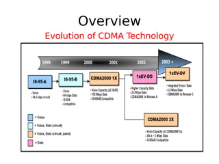
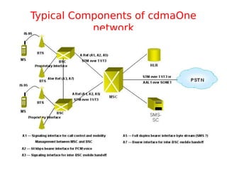
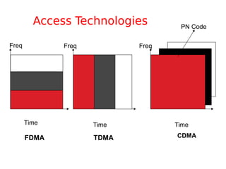
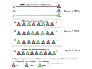
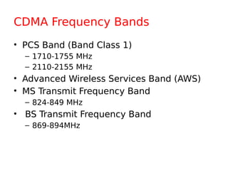
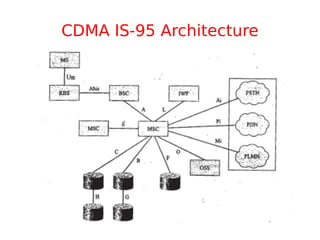
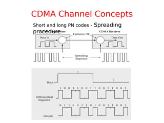
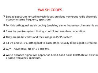
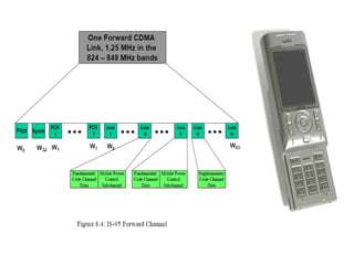
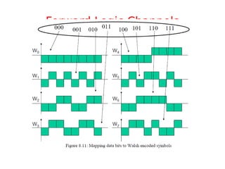
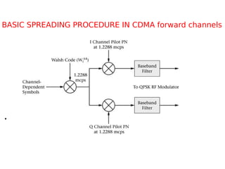
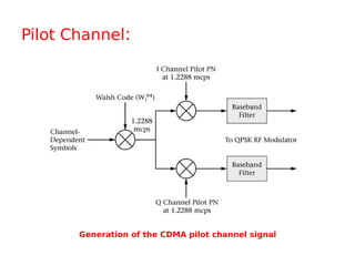
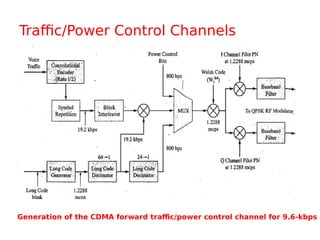
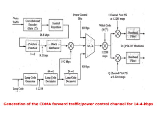
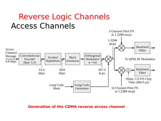
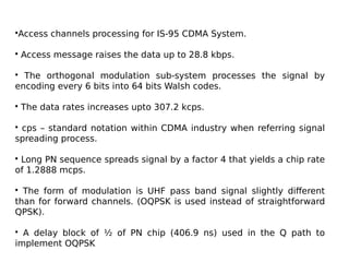
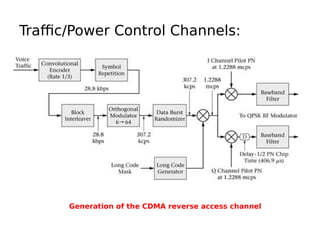
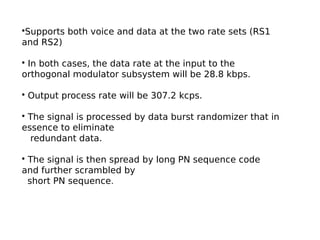
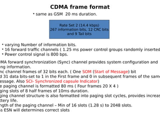
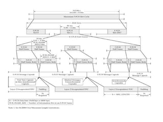
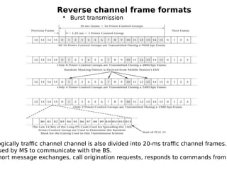
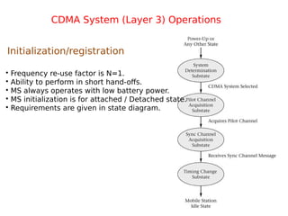
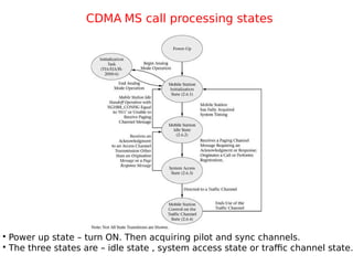
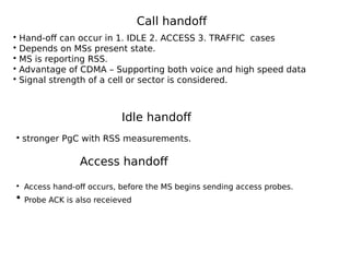
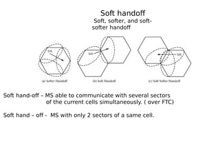
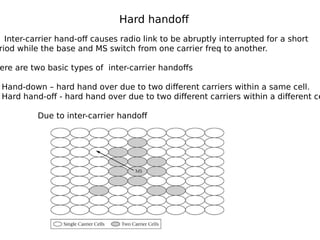
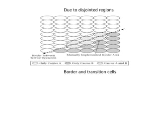
Unit – 6
CDMA Technology
Overview
Evolution of CDMA Technology
Typical Components of cdmaOne
network
Access Technologies
Time Time Time
Freq Freq Freq
PN Code
FDMA TDMA CDMA
CDMA Frequency Bands
• PCS Band (Band Class 1)
– 1710-1755 MHz
– 2110-2155 MHz
• Advanced Wireless Services Band (AWS)
• MS Transmit Frequency Band
– 824-849 MHz
• BS Transmit Frequency Band
– 869-894MHz
CDMA IS-95 Architecture
CDMA Channel Concepts
Short and long PN codes - Spreading
procedure
WALSH CODES
 Spread spectrum encoding techniques provides numerous radio channels
occupy in same frequency spectrum.
 For this orthogonal Walsh coding (enabling same frequency channels) is use
 Even for precise system timing, control and over-head operation.
 They are 64-bit codes and their usage in IS-95 system
 64 0’s and 64 1’s. orthogonal to each other. Usually 8-bit signal is created.
 W0
64
– have equal No of 1’s and 0’s.
 Walsh encoded signal will appear as broad-band noise CDMA Rx all exist in
a same frequency spectrum.
Forward Logic Channels
Basic spreading used on CDMA forward channels
cdmaOne Cells
144 kbps packet data
1.25 MHz channel
Moving to:
2 Mbps on 10MHz
TIMING OFFSET REUSE PATTERN
15
15
 The offset with BS used in CDMA
System must be all time synchronized
On the down link radio channels.
 The precise timing synchronization
Is achieved through the use of
The GPS.
CDMA base station timing offset reuse pattern
BASIC SPREADING PROCEDURE IN CDMA forward channels
•
•EX-ORing with particular Walsh code.
• Further scrambled into I and Q channels. (This
generates two different PN sequences)
• Not orthogonal with each other.
• Have cross and auto correlation properties.
• Short and Long PN sequence codes actually generated
by LFSRs.
• Approx Equal No of 1’s and 0’s a length of 32,768.
• Base band filters up-converts final o/p signal to UHF
bands.
Initial IS-95 CDMA used four different logical
channels:
• Pilot channel
• Synchronization Channel
• Paging Channels
• Traffic and Power Control Channels
Pilot Channel:
Generation of the CDMA pilot channel signal
• Provides a reference signal for all the SDs within a cell.
• The all 0s Walsh codes ( W0
64) used for initial signal
spreading on sequence of all 0’s.
• The I and Q signals drive QPSK modulator.
• Resulting signal is un-modulated spread spectrum signal.
• Short PN sequence is used to identify the Base station.
• 4-6 dB stronger than any other channel ( transmitted
power)
Synchronization Channel:
Generation of the CDMA synchronization channel signal
• Initial time synchronization.
• Here Walsh code W32
64 ( 32 0’s and 32 1’s) is used to
spread the synchronization channel signal.
• Even Synchronization channel message is also uses
(32 0’s and 32 1’s).
• Short PN sequence is with offset and is used for
further spreading.
• The synchronization message is about 1200 bps.
• The sync message undergoing convolution encoding,
symbol repetition and Block inter-leaving by raising
the rate to 4.6 kbps.
• Sync message includes system and Network
identification codes, paging channeldata rates, offset
values short PN spreading rate. ( Fixed o/p power)
Paging Channels:
Generation of the CDMA paging channel signal
• Same function as paging channel in GSM.
• Used to page the SDs when there is a mobile-terminated call
and sends control messages to the SDs.
• This is mainly used for call set-up.
• In IS-95, there are as many as 7 paging channels is in
operation at one time.
• WI
64
to W7
64
are used for this purpose.
• Additional Scrambling operation using long PN sequence.
• Generated by 42 bit LFSR (Linear Feedback Shift Register)
yielding repeating sequences (2 42
).
Traffic/Power Control Channels
Generation of the CDMA forward traffic/power control channel for 9.6-kbps
Generation of the CDMA forward traffic/power control channel for 14.4-kbps
• Traffic channels carry actual information ( Digitally encoded
voice or data)
• Different rate sets – Rate set 1 – 9.6 kbps (max) to
4.8,2.4,1.2 kbps.
• RS2- 14.4, 7.2, 3.6 , 1.8 kbps.
• Symbol repetition block – Data rate is doubled.
• The “ puncture” function block selects 4 out of 6 bits
offered and reduces the data rates to 19.2 kbps ( actually
from repetition – 14.4 X 2= 28.8 kbps)
• Then block interleaver prevents errors spreading.
• Further scrambling with long and short PN sequences
before transmission.
• Power control information is used to set the output power of
the mobile on the reverse link and is multiplexed with the
scrambled voice bits at a rate of 800 bps.
Reverse Logic Channels
Access Channels
Generation of the CDMA reverse access channel
•Access channels processing for IS-95 CDMA System.
• Access message raises the data up to 28.8 kbps.
• The orthogonal modulation sub-system processes the signal by
encoding every 6 bits into 64 bits Walsh codes.
• The data rates increases upto 307.2 kcps.
• cps – standard notation within CDMA industry when referring signal
spreading process.
• Long PN sequence spreads signal by a factor 4 that yields a chip rate
of 1.2888 mcps.
• The form of modulation is UHF pass band signal slightly different
than for forward channels. (OQPSK is used instead of straightforward
QPSK).
• A delay block of ½ of PN chip (406.9 ns) used in the Q path to
implement OQPSK
Traffic/Power Control Channels:
Generation of the CDMA reverse access channel
•Supports both voice and data at the two rate sets (RS1
and RS2)
• In both cases, the data rate at the input to the
orthogonal modulator subsystem will be 28.8 kbps.
• Output process rate will be 307.2 kcps.
• The signal is processed by data burst randomizer that in
essence to eliminate
redundant data.
• The signal is then spread by long PN sequence code
and further scrambled by
short PN sequence.
CDMA frame format
Rate Set 2 (14.4 kbps)
267 information bits, 12 CRC bits
and 9 Tail bits
• same as GSM 20 ms duration.
• varying Number of information bits.
• 16 forward traffic channels ( 1.25 ms power control groups randomly inserted
• Power control signal is 800 bps.
DMA forward synchronization (Sync) channel provides system configuration and
ing information.
nc channel frames of 32 bits each. ( One SOM (Start of Message) bit
d 31 data bits-set to 1 in the First frame and 0 in subsequent frames of the same
essage. Also SCI- Synchronized capsule Indicator)
e paging channel is formatted 80 ms ( Four frames 20 X 4 )
ging slots of 8 half frames of 10ms duration.
ging channel structure is also formatted into paging slot cycles, provides increas
ttery life.
ngth of the paging channel – Min of 16 slots (1.28 s) to 2048 slots.
Ss ESN will determines correct slots
Reverse channel frame formats
• Burst transmission
ogically traffic channel channel is also divided into 20-ms traffic channel frames.
sed by MS to communicate with the BS.
hort message exchanges, call origination requests, responds to commands from
CDMA System (Layer 3) Operations
Initialization/registration
• Frequency re-use factor is N=1.
• Ability to perform in short hand-offs.
• MS always operates with low battery power.
• MS initialization is for attached / Detached state.
• Requirements are given in state diagram.
CDMA MS call processing states
• Power up state – turn ON. Then acquiring pilot and sync channels.
• The three states are – idle state , system access state or traffic channel state.
System Access Flow Chart
Priority Access and Channel
Assignment
CDMA MS control on the traffic channel flow chart
Different Types Of Registration
OWER –UP – Different band classes or PCS frequency blocks in alternative
rating modes, or analog and CDMA operations.
OWER-DOWN – registers and powers off with previously serving station.
mer Based- various timers expires. The process forces the MS to register at
lar intervals.
stance- based :- Distance between current serving BS and Base station where
it last registered exceeds certain threshold. MS calculates this
distance by using the latitude and longitude values for the BSs.
one Based :- MS registers when it enters into new Zone. First five modes are
called as autonomous registration and enabled by roaming status.
rameter-change : considers some specific parameters stored in memory of MS
when enters to new zone.
dered :- Issue of ordered message ( requested by the BS)
mplicit :- page response message and origination message.
9. Traffic channel – BS registration message for a MS assigned to traffic channel
10. User Zone – MS selects active user zone.
1.Initialization state- MS searches pilot channel by aligning its short
its short PN sequence with short PN code received. Valid sync code
initialize MS. W32
64
Walsh switching is done.
2. Idle state – MS is waiting to receive calls or data messages or
ready to originate calls. Support for subscriber connectivity and
Mobility. Continually monitoring radio channel quality. Getting all
access parameters, it goes to SLEEP mode to conserve MS battery
Power.
3. Access state – The CDMA mobile will enter the access state when
It receives a mobile directed message requiring an
acknowledgement. It originates a call or required to perform
registration. Ms will randomly attempt to access the system. MS
receives a response from the BS on the paging channel. Collision
Avoidance is necessary for successful system access.
Call establishment
Access channel probing
Transmission of a series of access probe sequences is known as an access attemp
Each access probe consists of an access channel preamble ( 1-16 frames of 0’s).
Three to 10 frames ( Access channel message capsule)
This yields 4-26 number of 20 ms frames.
Two types of access messages – 1. Response message 2. Request message
• MS sending a series
Of sequences of
Access probes of
Increasing power
Levels.
• Repeated transmission
• Ack over paging channel.
• For MSs access attempt
Is un-successful, then
Further additional
Attempts with probe
Sequences is tried out.
Traffic state
• Call origination.
• Information – Either voice or Data.
• MS transmits voice and signaling information on the FTC.
• Blank –end-burst – signaling replaces 1.25 ms of speech data with signaling
message bursts.
dim-end-burst – inserts signaling messages when speech activity is low.
Mobile-originated call
• If the access is successful, then
FTC corresponds to particular
Walsh code.
• Preamble information sent by MS.
• Paging channel information is sent
By MS.
Mobile-terminated call
• BS sends a message to the MS on the paging
Channel.
• If it attached to the system, MS sends ACK
On access channel.
• MS configures itself.
Call handoff
Idle handoff
• Hand-off can occur in 1. IDLE 2. ACCESS 3. TRAFFIC cases
• Depends on MSs present state.
• MS is reporting RSS.
• Advantage of CDMA – Supporting both voice and high speed data
• Signal strength of a cell or sector is considered.
• stronger PgC with RSS measurements.
Access handoff
• Access hand-off occurs, before the MS begins sending access probes.
• Probe ACK is also receieved
Soft handoff
Soft, softer, and soft-
softer handoff
. Soft hand-off – MS able to communicate with several sectors
of the current cells simultaneously. ( over FTC)
. Soft hand – off - MS with only 2 sectors of a same cell.
Hard handoff
Inter-carrier hand-off causes radio link to be abruptly interrupted for a short
riod while the base and MS switch from one carrier freq to another.
ere are two basic types of inter-carrier handoffs
Hand-down – hard hand over due to two different carriers within a same cell.
Hard hand-off - hard hand over due to two different carriers within a different ce
Due to inter-carrier handoff
Due to disjointed regions
Border and transition cells

cdma-technology_compress.pdf

  • 1.
    Unit – 6 CDMATechnology
  • 2.
  • 3.
    Typical Components ofcdmaOne network
  • 5.
    Access Technologies Time TimeTime Freq Freq Freq PN Code FDMA TDMA CDMA
  • 7.
    CDMA Frequency Bands •PCS Band (Band Class 1) – 1710-1755 MHz – 2110-2155 MHz • Advanced Wireless Services Band (AWS) • MS Transmit Frequency Band – 824-849 MHz • BS Transmit Frequency Band – 869-894MHz
  • 8.
  • 9.
    CDMA Channel Concepts Shortand long PN codes - Spreading procedure
  • 10.
    WALSH CODES  Spreadspectrum encoding techniques provides numerous radio channels occupy in same frequency spectrum.  For this orthogonal Walsh coding (enabling same frequency channels) is use  Even for precise system timing, control and over-head operation.  They are 64-bit codes and their usage in IS-95 system  64 0’s and 64 1’s. orthogonal to each other. Usually 8-bit signal is created.  W0 64 – have equal No of 1’s and 0’s.  Walsh encoded signal will appear as broad-band noise CDMA Rx all exist in a same frequency spectrum.
  • 12.
    Forward Logic Channels Basicspreading used on CDMA forward channels
  • 13.
    cdmaOne Cells 144 kbpspacket data 1.25 MHz channel Moving to: 2 Mbps on 10MHz TIMING OFFSET REUSE PATTERN 15 15  The offset with BS used in CDMA System must be all time synchronized On the down link radio channels.  The precise timing synchronization Is achieved through the use of The GPS.
  • 14.
    CDMA base stationtiming offset reuse pattern
  • 15.
    BASIC SPREADING PROCEDUREIN CDMA forward channels •
  • 16.
    •EX-ORing with particularWalsh code. • Further scrambled into I and Q channels. (This generates two different PN sequences) • Not orthogonal with each other. • Have cross and auto correlation properties. • Short and Long PN sequence codes actually generated by LFSRs. • Approx Equal No of 1’s and 0’s a length of 32,768. • Base band filters up-converts final o/p signal to UHF bands.
  • 17.
    Initial IS-95 CDMAused four different logical channels: • Pilot channel • Synchronization Channel • Paging Channels • Traffic and Power Control Channels
  • 18.
    Pilot Channel: Generation ofthe CDMA pilot channel signal
  • 19.
    • Provides areference signal for all the SDs within a cell. • The all 0s Walsh codes ( W0 64) used for initial signal spreading on sequence of all 0’s. • The I and Q signals drive QPSK modulator. • Resulting signal is un-modulated spread spectrum signal. • Short PN sequence is used to identify the Base station. • 4-6 dB stronger than any other channel ( transmitted power)
  • 20.
    Synchronization Channel: Generation ofthe CDMA synchronization channel signal
  • 21.
    • Initial timesynchronization. • Here Walsh code W32 64 ( 32 0’s and 32 1’s) is used to spread the synchronization channel signal. • Even Synchronization channel message is also uses (32 0’s and 32 1’s). • Short PN sequence is with offset and is used for further spreading. • The synchronization message is about 1200 bps. • The sync message undergoing convolution encoding, symbol repetition and Block inter-leaving by raising the rate to 4.6 kbps. • Sync message includes system and Network identification codes, paging channeldata rates, offset values short PN spreading rate. ( Fixed o/p power)
  • 22.
    Paging Channels: Generation ofthe CDMA paging channel signal
  • 23.
    • Same functionas paging channel in GSM. • Used to page the SDs when there is a mobile-terminated call and sends control messages to the SDs. • This is mainly used for call set-up. • In IS-95, there are as many as 7 paging channels is in operation at one time. • WI 64 to W7 64 are used for this purpose. • Additional Scrambling operation using long PN sequence. • Generated by 42 bit LFSR (Linear Feedback Shift Register) yielding repeating sequences (2 42 ).
  • 24.
    Traffic/Power Control Channels Generationof the CDMA forward traffic/power control channel for 9.6-kbps
  • 25.
    Generation of theCDMA forward traffic/power control channel for 14.4-kbps
  • 26.
    • Traffic channelscarry actual information ( Digitally encoded voice or data) • Different rate sets – Rate set 1 – 9.6 kbps (max) to 4.8,2.4,1.2 kbps. • RS2- 14.4, 7.2, 3.6 , 1.8 kbps. • Symbol repetition block – Data rate is doubled. • The “ puncture” function block selects 4 out of 6 bits offered and reduces the data rates to 19.2 kbps ( actually from repetition – 14.4 X 2= 28.8 kbps) • Then block interleaver prevents errors spreading. • Further scrambling with long and short PN sequences before transmission. • Power control information is used to set the output power of the mobile on the reverse link and is multiplexed with the scrambled voice bits at a rate of 800 bps.
  • 27.
    Reverse Logic Channels AccessChannels Generation of the CDMA reverse access channel
  • 28.
    •Access channels processingfor IS-95 CDMA System. • Access message raises the data up to 28.8 kbps. • The orthogonal modulation sub-system processes the signal by encoding every 6 bits into 64 bits Walsh codes. • The data rates increases upto 307.2 kcps. • cps – standard notation within CDMA industry when referring signal spreading process. • Long PN sequence spreads signal by a factor 4 that yields a chip rate of 1.2888 mcps. • The form of modulation is UHF pass band signal slightly different than for forward channels. (OQPSK is used instead of straightforward QPSK). • A delay block of ½ of PN chip (406.9 ns) used in the Q path to implement OQPSK
  • 29.
    Traffic/Power Control Channels: Generationof the CDMA reverse access channel
  • 30.
    •Supports both voiceand data at the two rate sets (RS1 and RS2) • In both cases, the data rate at the input to the orthogonal modulator subsystem will be 28.8 kbps. • Output process rate will be 307.2 kcps. • The signal is processed by data burst randomizer that in essence to eliminate redundant data. • The signal is then spread by long PN sequence code and further scrambled by short PN sequence.
  • 31.
    CDMA frame format RateSet 2 (14.4 kbps) 267 information bits, 12 CRC bits and 9 Tail bits • same as GSM 20 ms duration. • varying Number of information bits. • 16 forward traffic channels ( 1.25 ms power control groups randomly inserted • Power control signal is 800 bps. DMA forward synchronization (Sync) channel provides system configuration and ing information. nc channel frames of 32 bits each. ( One SOM (Start of Message) bit d 31 data bits-set to 1 in the First frame and 0 in subsequent frames of the same essage. Also SCI- Synchronized capsule Indicator) e paging channel is formatted 80 ms ( Four frames 20 X 4 ) ging slots of 8 half frames of 10ms duration. ging channel structure is also formatted into paging slot cycles, provides increas ttery life. ngth of the paging channel – Min of 16 slots (1.28 s) to 2048 slots. Ss ESN will determines correct slots
  • 33.
    Reverse channel frameformats • Burst transmission ogically traffic channel channel is also divided into 20-ms traffic channel frames. sed by MS to communicate with the BS. hort message exchanges, call origination requests, responds to commands from
  • 34.
    CDMA System (Layer3) Operations Initialization/registration • Frequency re-use factor is N=1. • Ability to perform in short hand-offs. • MS always operates with low battery power. • MS initialization is for attached / Detached state. • Requirements are given in state diagram.
  • 35.
    CDMA MS callprocessing states • Power up state – turn ON. Then acquiring pilot and sync channels. • The three states are – idle state , system access state or traffic channel state.
  • 36.
    System Access FlowChart Priority Access and Channel Assignment
  • 37.
    CDMA MS controlon the traffic channel flow chart
  • 38.
    Different Types OfRegistration OWER –UP – Different band classes or PCS frequency blocks in alternative rating modes, or analog and CDMA operations. OWER-DOWN – registers and powers off with previously serving station. mer Based- various timers expires. The process forces the MS to register at lar intervals. stance- based :- Distance between current serving BS and Base station where it last registered exceeds certain threshold. MS calculates this distance by using the latitude and longitude values for the BSs. one Based :- MS registers when it enters into new Zone. First five modes are called as autonomous registration and enabled by roaming status. rameter-change : considers some specific parameters stored in memory of MS when enters to new zone. dered :- Issue of ordered message ( requested by the BS) mplicit :- page response message and origination message.
  • 39.
    9. Traffic channel– BS registration message for a MS assigned to traffic channel 10. User Zone – MS selects active user zone.
  • 40.
    1.Initialization state- MSsearches pilot channel by aligning its short its short PN sequence with short PN code received. Valid sync code initialize MS. W32 64 Walsh switching is done. 2. Idle state – MS is waiting to receive calls or data messages or ready to originate calls. Support for subscriber connectivity and Mobility. Continually monitoring radio channel quality. Getting all access parameters, it goes to SLEEP mode to conserve MS battery Power. 3. Access state – The CDMA mobile will enter the access state when It receives a mobile directed message requiring an acknowledgement. It originates a call or required to perform registration. Ms will randomly attempt to access the system. MS receives a response from the BS on the paging channel. Collision Avoidance is necessary for successful system access. Call establishment
  • 41.
    Access channel probing Transmissionof a series of access probe sequences is known as an access attemp Each access probe consists of an access channel preamble ( 1-16 frames of 0’s). Three to 10 frames ( Access channel message capsule) This yields 4-26 number of 20 ms frames. Two types of access messages – 1. Response message 2. Request message • MS sending a series Of sequences of Access probes of Increasing power Levels. • Repeated transmission • Ack over paging channel. • For MSs access attempt Is un-successful, then Further additional Attempts with probe Sequences is tried out.
  • 42.
    Traffic state • Callorigination. • Information – Either voice or Data. • MS transmits voice and signaling information on the FTC. • Blank –end-burst – signaling replaces 1.25 ms of speech data with signaling message bursts. dim-end-burst – inserts signaling messages when speech activity is low. Mobile-originated call • If the access is successful, then FTC corresponds to particular Walsh code. • Preamble information sent by MS. • Paging channel information is sent By MS.
  • 43.
    Mobile-terminated call • BSsends a message to the MS on the paging Channel. • If it attached to the system, MS sends ACK On access channel. • MS configures itself.
  • 44.
    Call handoff Idle handoff •Hand-off can occur in 1. IDLE 2. ACCESS 3. TRAFFIC cases • Depends on MSs present state. • MS is reporting RSS. • Advantage of CDMA – Supporting both voice and high speed data • Signal strength of a cell or sector is considered. • stronger PgC with RSS measurements. Access handoff • Access hand-off occurs, before the MS begins sending access probes. • Probe ACK is also receieved
  • 45.
    Soft handoff Soft, softer,and soft- softer handoff . Soft hand-off – MS able to communicate with several sectors of the current cells simultaneously. ( over FTC) . Soft hand – off - MS with only 2 sectors of a same cell.
  • 46.
    Hard handoff Inter-carrier hand-offcauses radio link to be abruptly interrupted for a short riod while the base and MS switch from one carrier freq to another. ere are two basic types of inter-carrier handoffs Hand-down – hard hand over due to two different carriers within a same cell. Hard hand-off - hard hand over due to two different carriers within a different ce Due to inter-carrier handoff
  • 47.
    Due to disjointedregions Border and transition cells