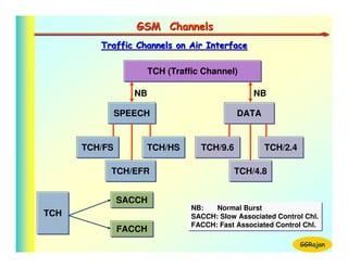
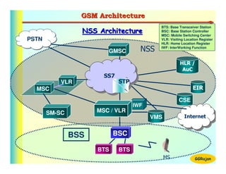
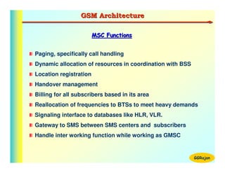
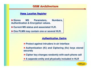
The document discusses GSM architecture and frequency planning. It describes the key components of GSM including the base station subsystem (BSS) with base transceiver stations (BTS) and base station controllers (BSC), and the network switching subsystem (NSS) with mobile switching centers (MSC). It also covers GSM frequency bands and channel allocation using frequency reuse patterns like 4/12 layout to maximize capacity while minimizing interference between cells. Sectorization is discussed as a way to increase capacity by splitting each cell site into multiple sectors.

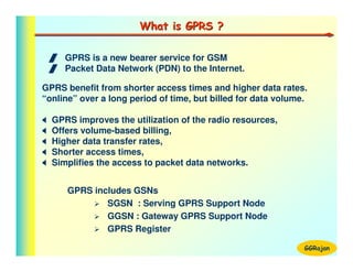
![GSM Frequency Spectrum
1] GSM 900
1] GSM 900
Uplink
Uplink : 890 MHz to 915 MHz
: 890 MHz to 915 MHz
GSM Spectrum
Downlink : 935 MHz to 960 MHz
Downlink : 935 MHz to 960 MHz
ARFCN
ARFCN : 124
: 124
2] EGSM 900
2] EGSM 900
Uplink
Uplink : 880 MHz to 915 MHz
: 880 MHz to 915 MHz 3] GSM 1800 (DCS 1800)
3] GSM 1800 (DCS 1800)
Downlink : 925 MHz to 960 MHz
Downlink : 925 MHz to 960 MHz Uplink
Uplink : 1710 MHz to 1795 MHz
: 1710 MHz to 1795 MHz
ARFCNs : 174
ARFCNs : 174 Downlink : 1805 MHz to 1880 MHz
Downlink : 1805 MHz to 1880 MHz
ARFCNs : 374
ARFCNs : 374
Absolute Radio Frequency Channels : 4] PCS 1900
4] PCS 1900
BW - 200 KHz, TDMA Slots - 8 Uplink
Uplink : 1850 MHz to 1910 MHz
: 1850 MHz to 1910 MHz
Downlink : 1930 MHz to 1990 MHz
Downlink : 1930 MHz to 1990 MHz
ARFCNs : 299
ARFCNs : 299 GGRajan](https://image.slidesharecdn.com/gsmtechnology-110929125504-phpapp02/85/Gsm-technology-4-320.jpg)
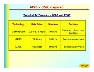
![GSM Frequency Spectrum
GSM Spectrum [900 MHz]
Time
Code
• UL band : 890 - 915 MHz
• DL band : 935 - 960 MHz TS-8
• Duplex spacing: 45 MHz
A
FDMA structure: 124 RFs (ARFCN) TS-2
M
•
TD
TS-1
• RF Band width: 200 KHz
Freq
• TDMA structure: 8 Timeslots/ RF RF-1 RF-2 RF-3
FDMA
960 Mhz
124
•
•
RF • 1 2 3 4 5 6 7 8
•
2 TDMA structure of each ARFCN
1
935 Mhz
GGRajan](https://image.slidesharecdn.com/gsmtechnology-110929125504-phpapp02/85/Gsm-technology-5-320.jpg)


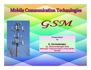
![SIM Anatomy
Programs in SIM
1 . IMSI (International Mobile Station Identity)
2 . Ki (Individual Subscriber authentication Key)
3 . A3 (Authentication Algorithm )
4 . A8 [ Cipher Key (Kc) Algorithm ]
IMSI
Ki
5 . A5 (Encryption Algorithm ) A3
A8
• IMSI & Ki are specific to each MS A5
• A3 & A8 can be different for different operators
• A5 - Unique, used across GSM operators
GGRajan](https://image.slidesharecdn.com/gsmtechnology-110929125504-phpapp02/85/Gsm-technology-27-320.jpg)