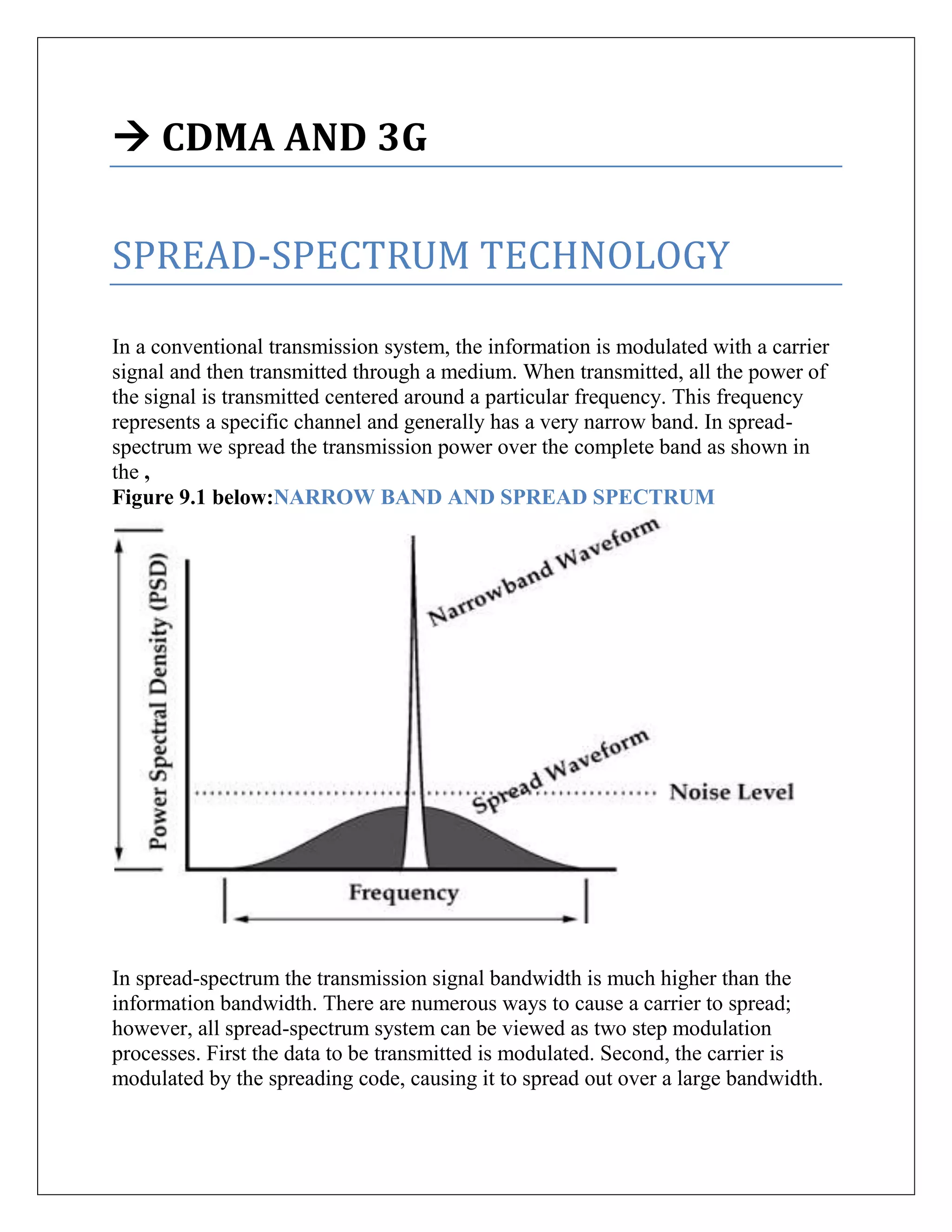
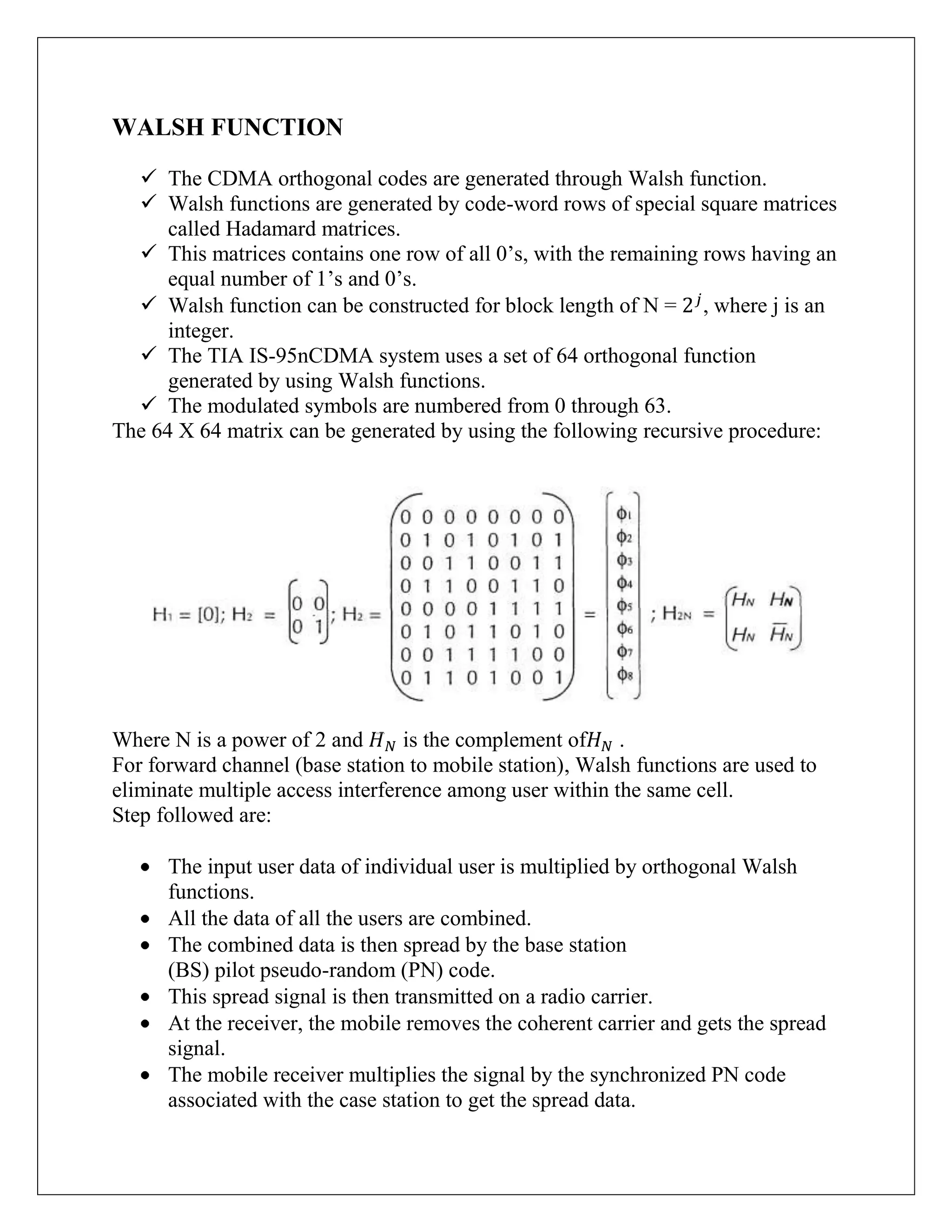
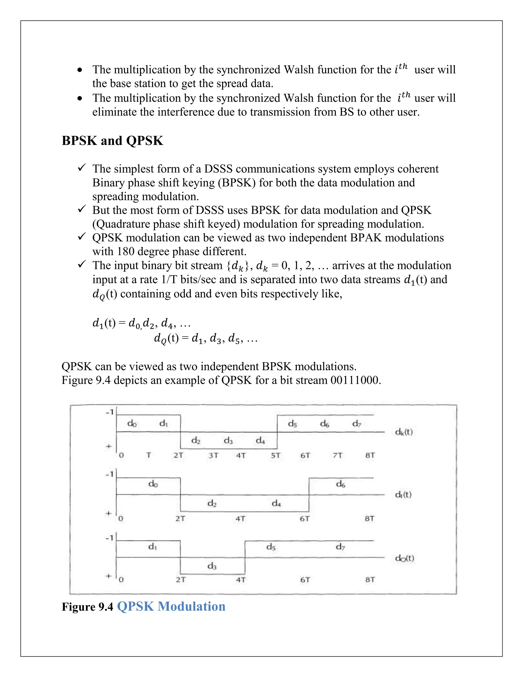
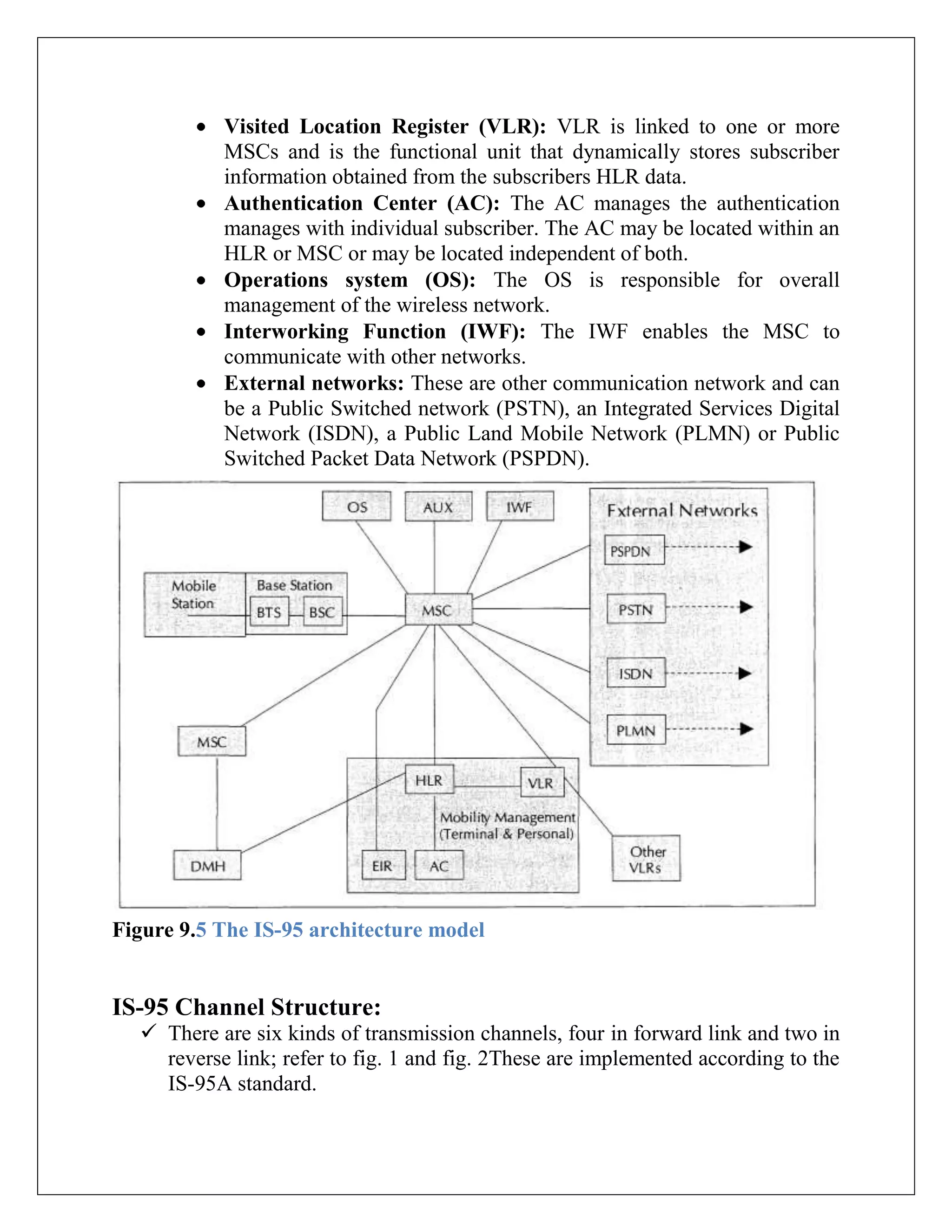
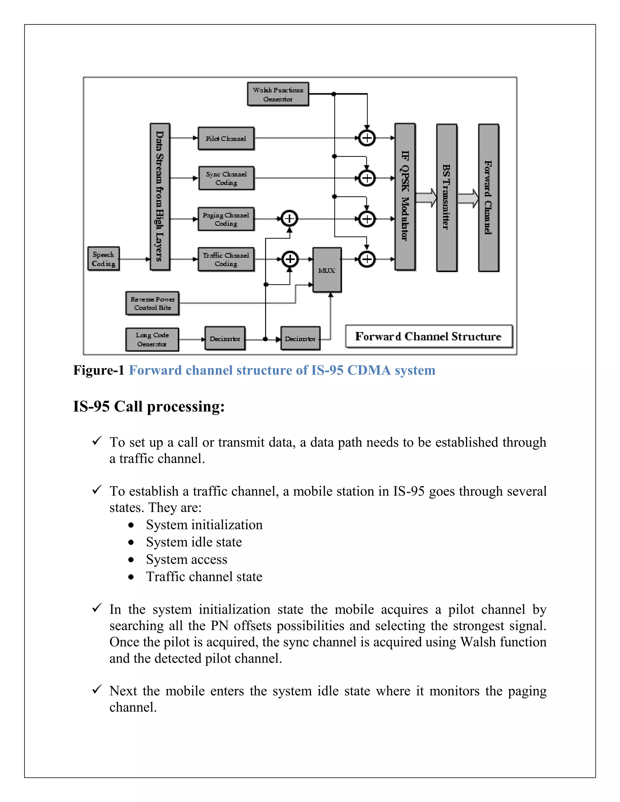
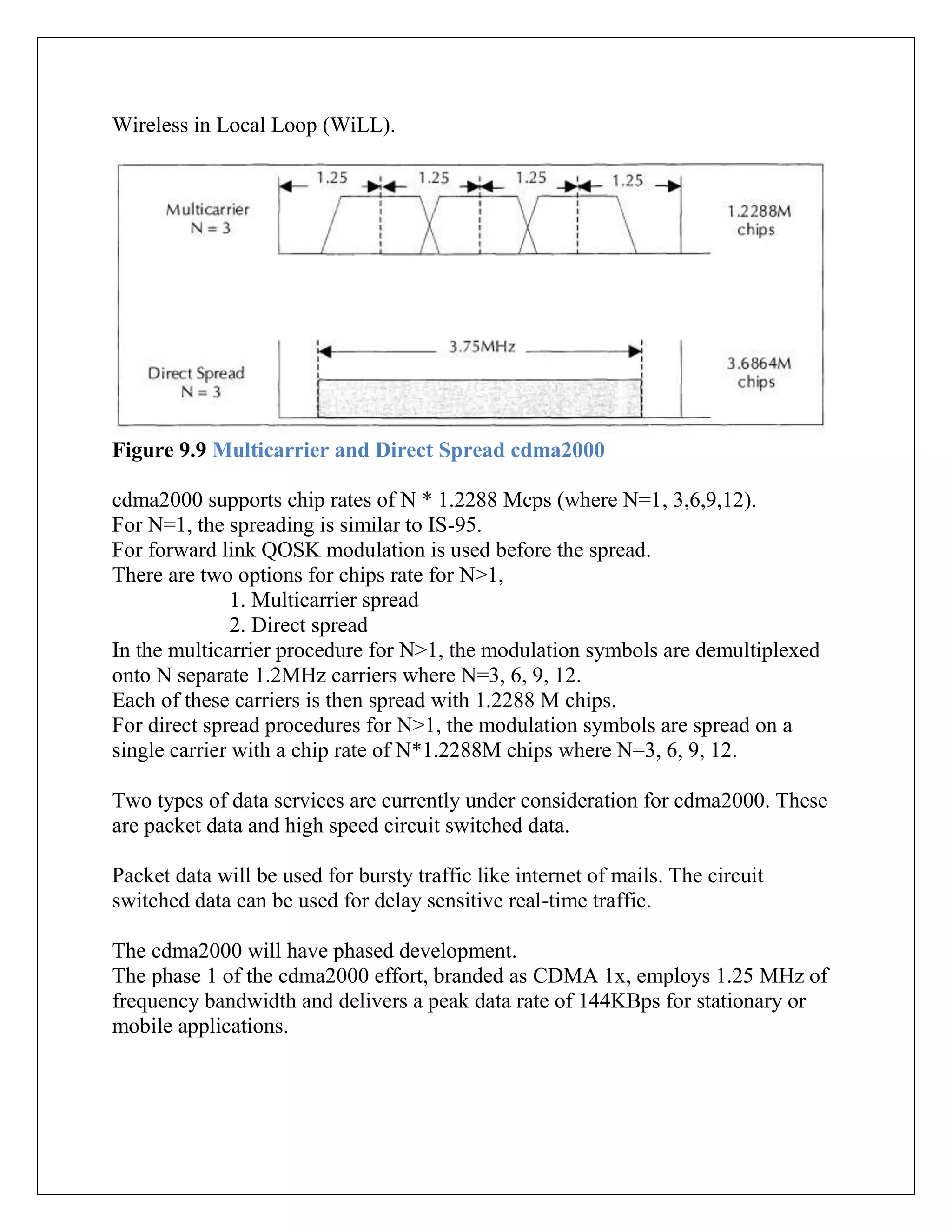
The document discusses CDMA and 3G spread spectrum technology. It describes how CDMA uses direct sequence spread spectrum to allow multiple users to access the same frequency band simultaneously. It explains the key elements of spread spectrum communication including using a chip rate that is faster than the data rate, synchronization at the receiver, and using pseudo-random codes. It provides details on IS-95 CDMA including channel structures, call processing, and authentication.
Students, digital devices and success - Andreas Schleicher - 27 May 2024..pptx
Cdma and 3 g
1. CDMA AND 3G
SPREAD-SPECTRUM TECHNOLOGY
In a conventional transmission system, the information is modulated with a carrier
signal and then transmitted through a medium. When transmitted, all the power of
the signal is transmitted centered around a particular frequency. This frequency
represents a specific channel and generally has a very narrow band. In spread-
spectrum we spread the transmission power over the complete band as shown in
the ,
Figure 9.1 below:NARROW BAND AND SPREAD SPECTRUM
In spread-spectrum the transmission signal bandwidth is much higher than the
information bandwidth. There are numerous ways to cause a carrier to spread;
however, all spread-spectrum system can be viewed as two step modulation
processes. First the data to be transmitted is modulated. Second, the carrier is
modulated by the spreading code, causing it to spread out over a large bandwidth.
2. Different spreading techniques are:
Direct spread (DS):DS spread spectrum is typically used to transmit
digital information. A common practice in DS system is to mix the digital
information stream with a pseudo random code.
Frequency Hopping (FH): frequency hopping is a form of spreading in
which the center frequency of the conventional carrier is altered many times
with a fixed time period (like one second) in accordance with a pseudo-
random list of channels.
Time Hopping: The last spreading method is called time hopping. In a
time hopped signal, the carrier is on-off keyed by the pseudo-noise (PN)
sequence resulting in a very low duty cycle. The speedof keying determines
the amount of signal spreading.
Hybrid System: A hybrid system combines the best points of two or
more spread-spectrum system. The performance of the hybrid system is
usually better than can be obtained with a single spread-spectrum technique
for the same cost. The most common hybrid combines both frequency-
hopping and direct-sequence techniques.
Amateurs and business communities are currently authorized to use only two
spreading techniques. These are frequency hopping and direct-sequence
techniques. Rest of the spread-spectrum technologies are classified and used by
military and space sciences.
Direct sequence spread-spectrum(DSSS)
Direct sequence spread spectrum (DSSS) is often compared to a party, where many
pairs are conversing, each in a different language. Each pair understands only one
language and therefore, concentrates on his or her own conversation, ignoring the
rest.
In general the spread-spectrum communication is distinguished by three key
elements:
The signal occupies a bandwidth much larger than what is necessary to send
the information.
3. The bandwidth is spread by the means of a clock, which is independent of
the data.
The receiver synchronization to the code to recover the data. The use of an
independent code and synchronous reception allows multiple users to access
the same frequency band at the same time.
In order to protect the signal, the code used is pseudo-random, which makes it
appear random while being actually deterministic, which enables the receiver to
reconstruct the code for synchronous detection.
This pseudo-random code is also called pseudo-noise (PN).
DSSS is commonly called code division multiple access or CDMA in short.
Each station is assigned a unique m-bit code. This code is called the CDMA
chip sequence.
To transmit a 1 bit, the transmission station sends its chips sequence,
whereas to send 0, it sends the complement chip sequence.
Thus if station A is assigned the chip sequence 000110011, it sends bit 1 by
sending 00011011 and bit 0 by sending 11100100.
Using bipolar notations, we define bit 0 as +1 and bit 1 as -1. The bit 0 for
station A will now become (-1 -1 -1 +1 +1 -1 +1 +1) and 1 becomes (+1 +1
+1 -1 -1 +1 -1 -1 )
Figure 9.3 below depict this with 6 chips/ bit (011010).
For manipulation of bits, we XOR (addition with modulo 2) the input bits, in
bipolar notations we multiply to get the desired result:
0 XOR 0 = 0 +1 x +1 = +1
1 XOR 1 = 0 -1 x -1 = +1
1 XOR 0 = 1 -1 x +1 = -1
0 XOR 1 = 1 +1 x -1 =-1
Each station has its unique chip sequence. Let us use the symbol S to
indicate the m-chip vector for station S, and is for its negation.
All chip sequence are pair-wise orthogonal, by which we mean that the
normalized inner product of any two distinct chip sequence, S and T (written
as S·T) is 0. In mathematical terms,
4. This orthogonal property is very crucial for mobile computing.
Note ifS·T = 0 then S·T is also 0.
The normalized inner product of any chip sequence with itself is 1.
This follows because each of the m terms in the inner product is 1, so the
sum is m.
Also note that · =1.
Figure 9.2 TheCDMA chip sequence.
5. In Figure 9.3 given below, we see there are four stations A, B, C and D with their
chip sequence. In this example, we have taken eight chips.
Figure 9.3(a) is the bit sequence of the chip.
Figure 9.3(b) is the bipolar notations of the same.
Figure 9.3(c), we assume that there are six cases of four stations
transmitting at the same time.
In the first example, Figure 9.3(c), we assume that only C is transmitting bit 1. In
the second example, B transmits a bit 1, and C transmits a bit 1.
Therefore we get:
(-1 +1 -1 +1 +1 +1 -1 -1) =
(-1 -1 +1 -1 +1 +1 +1 -1)+ (-1 +1 -1 +1 +1 +1 -1 -1)=(-2 0 0 0 +2 +2 0 -2)=
In the third example, station A transmits a 1 and station B transmits a 0, other is
silent. In the fourth example, A and C transmits a 1 while B sends 0. In the fifth
example, all four station transmits 1 and. Finally, in the last example, A, B, and D
transmits a 1, while C sends a 0.
The result of these transmissions is different sequences through as given
Figure 9.3(d). All these examples represent only one bit time.
Figure 9.3 CDMA Code Arithmetic
6. WALSH FUNCTION
The CDMA orthogonal codes are generated through Walsh function.
Walsh functions are generated by code-word rows of special square matrices
called Hadamard matrices.
This matrices contains one row of all 0‟s, with the remaining rows having an
equal number of 1‟s and 0‟s.
Walsh function can be constructed for block length of N = , where j is an
integer.
The TIA IS-95nCDMA system uses a set of 64 orthogonal function
generated by using Walsh functions.
The modulated symbols are numbered from 0 through 63.
The 64 X 64 matrix can be generated by using the following recursive procedure:
Where N is a power of 2 and is the complement of .
For forward channel (base station to mobile station), Walsh functions are used to
eliminate multiple access interference among user within the same cell.
Step followed are:
The input user data of individual user is multiplied by orthogonal Walsh
functions.
All the data of all the users are combined.
The combined data is then spread by the base station
(BS) pilot pseudo-random (PN) code.
This spread signal is then transmitted on a radio carrier.
At the receiver, the mobile removes the coherent carrier and gets the spread
signal.
The mobile receiver multiplies the signal by the synchronized PN code
associated with the case station to get the spread data.
7. The multiplication by the synchronized Walsh function for the user will
the base station to get the spread data.
The multiplication by the synchronized Walsh function for the user will
eliminate the interference due to transmission from BS to other user.
BPSK and QPSK
The simplest form of a DSSS communications system employs coherent
Binary phase shift keying (BPSK) for both the data modulation and
spreading modulation.
But the most form of DSSS uses BPSK for data modulation and QPSK
(Quadrature phase shift keyed) modulation for spreading modulation.
QPSK modulation can be viewed as two independent BPAK modulations
with 180 degree phase different.
The input binary bit stream { }, = 0, 1, 2, … arrives at the modulation
input at a rate 1/T bits/sec and is separated into two data streams (t) and
(t) containing odd and even bits respectively like,
(t) = , , …
(t) = , , , …
QPSK can be viewed as two independent BPSK modulations.
Figure 9.4 depicts an example of QPSK for a bit stream 00111000.
Figure 9.4 QPSK Modulation
8. IS-95
The IS-95 standard describes a Code Division Multiple Access (CDMA)
system in which the audio and data signal is multiplied by a high rate
spreadingsignal.
This spreading signal is formed from a pseudo-noise code sequence,which is
then multiplied by a Walsh code for maximum orthogonality to (i.e. Tohave
low cross-correlation with) the other codes in use in that cell.
Typically,CDMA pseudo-noise sequences are very long, thereby giving
excellent cross-correlation characteristics. (IS-95 uses a 242-1 chip period,
derived from a 42 bitmask.)
The IS-95 system can be thought of as having many layers of
protectionagainst interference.
It allows many users to co-exist, with minimal mutual interference.
The forward channel carries information from the base station to the mobile
unit;the reverse channel carries information from the mobile unit to the base
station.
The forward channels are between 869 and 894 MHz, while the reverse
channels are between 824 and 849 MHz.
Speech and channel coding:
Normal audio range of human being is between 20 to 20 KHz. This range is
normally used for high fidelity CD quality music.
For telephonic communication where human voice is used, the frequency
range of 300 to 3300 Hz is sufficient.
9. For digitizing the speech, it is sufficient to sample at 8000 samples per
second.
To achieve telephone quality speech, 12 bits are sufficient to encode each
sample.
12 bits is reduced to 8 bits per sample using logarithms.
This result in encoding of the speech and digitization of voice into 64 KBps.
This digitized voice is then passed through a coding scheme using Code-
Excited Linear Prediction (CELP) algorithm.
Linear Prediction Coding (LPC) is a combination of waveform coder and
vocoder.
In mobile telecommunication environment, signal strength varies with
location and movement of the mobile transmitter/receiver.
Signal strength influences error rates which in turn affects the quality of
communications.
IS-95 addresses the problem of burst error by utilizing an error correction
scheme based on encoding and interleaving.
Interleaving is a technique in which encoded digital data is reordered before
transmission in such a manner that two successive digital data bits in the
original data stream are separated by a predetermined distance in the
transmitted data stream.
IS-95 Architecture:
The main elements of IS-95 reference model are:
Mobile station (MS): This is the mobile phone unit with the user.
The MS terminate the radio path on the user side and unable the user
10. to gain access from the network. The MS can be stand alone device. It
can have other devices (e.g. personal computer, fax machines)
connected to where it works as a pass through.
Base Station (BS): The BS terminates the radio path that connects the
mobile switching center (MSC). BS is a system between the MS and
MSC. The BS is segmented into BTS and BSC.
o Base Transceiver Station (BTS): BTS consists of one or more
transceiver placed at a single location and terminates the radio
path on the network side.
o Base Station Controller (BSC): the BSC is the control and
management system for one or more BTSs. The BSC exchange
messages with both the BTS and the MSC.
Mobile Switching Center (MSC): This is the main
switchingcenterequivalent to the telephone exchange in a fixed
network. The MSC does one or more of the following function:
o Anchor MSC: First MSC providing radio contact to a call
o Border MSC: An MSC controlling BTSs adjacent to the
location of the mobile station.
o Candidate MSC: An MSC that could possibly accept a call or a
handoff.
o Originating MSC: The MSC directing an incoming call
towards a mobile station.
o Remote MSC: The MSC at the other end of an intersystem
trunk.
o Serving MSC: The MSC currently providing service to a call.
o Tandem MSC: An MSC providing only trunk connections for a
call in which a handoff has occurred.
o Target MSC: The MSC selected for a handoff.
o Visited MSC: The MSC providing service to the mobile
station.
Home Location Register (HLR):HLR is the functional unit that
manages mobile subscriber by maintaining all subscriber related
information. The HLR can serve multiple MSC or may be distributed
over multiple locations.
Data Message Handler (DMH): The DMH is responsible for
collating the billing data.
11. Visited Location Register (VLR): VLR is linked to one or more
MSCs and is the functional unit that dynamically stores subscriber
information obtained from the subscribers HLR data.
Authentication Center (AC): The AC manages the authentication
manages with individual subscriber. The AC may be located within an
HLR or MSC or may be located independent of both.
Operations system (OS): The OS is responsible for overall
management of the wireless network.
Interworking Function (IWF): The IWF enables the MSC to
communicate with other networks.
External networks: These are other communication network and can
be a Public Switched network (PSTN), an Integrated Services Digital
Network (ISDN), a Public Land Mobile Network (PLMN) or Public
Switched Packet Data Network (PSPDN).
Figure 9.5 The IS-95 architecture model
IS-95 Channel Structure:
There are six kinds of transmission channels, four in forward link and two in
reverse link; refer to fig. 1 and fig. 2These are implemented according to the
IS-95A standard.
12. Pilot channel: an unmodulated, direct-sequence spread spectrum
signal is transmitted continuously by each CDMA base station. Pilot
channel allows a mobile station to acquire the timing of the forward
CDMA channel.
Sync channel:sync channel is used to obtain initial time
synchronization.
Paging channel: a code channel in a forward CDMA channel is used
to transmit control information and pages from a base station to a
mobile station.
Forward traffic channel: forward traffic channel is used for the
transmission of user and signaling information to a specific mobile
station during a call.
Access channel: access channel is used by the mobile station to
initiate communication with the base station and to respond to paging
channel messages.
Reverse traffic channel: Reverse traffic channel is used for user
transmission and signaling information to the base station during a
call.
Figure 9.6 IS-95 Forward and Reverse link channel structure
13. Figure-1 Forward channel structure of IS-95 CDMA system
IS-95 Call processing:
To set up a call or transmit data, a data path needs to be established through
a traffic channel.
To establish a traffic channel, a mobile station in IS-95 goes through several
states. They are:
System initialization
System idle state
System access
Traffic channel state
In the system initialization state the mobile acquires a pilot channel by
searching all the PN offsets possibilities and selecting the strongest signal.
Once the pilot is acquired, the sync channel is acquired using Walsh function
and the detected pilot channel.
Next the mobile enters the system idle state where it monitors the paging
channel.
14. It the call is being placed or received, the mobile enters the access state
where the necessary parameters are exchange.
CDMA Registration:
The registration process is used by the mobile device to notify its locations,
status, identification and other characteristics.
Location information is required to page the mobile for an incoming
terminated call.
Authentication and security:
In the authentication process, information is exchanged between an MS and
a BS to confirm the identity of the MS. A successful authentication process
occurs only when it is demonstrated that the MS and BS possess identical
sets of Shared Secret Data (SSD).
The MS uses the operational IMSI (IMSI_O) for authentication purposes,
and the BS uses the IMSI associated with the last MS registration.
The spreading PN (Pseudorandom Noise) sequence also play a role in
security.
Handoff and Roaming:
A handover in GSM is called handoff in IS-95.
When the subscriber moves away from a base station, the signal power
reduces resulting in potential drop in connection.
To ensure that the call does not break, some other base station closer to the
mobile station needs to attach the mobile to it and let the call continue
without any interruption.
There are three types of handoffs in CDMA:
15. Soft handoff:
o The MS (Mobile Station) receives /transmits the same signals
from/to multiple BSs (Base stations) simultaneously.
o The network must combine the signals from the multiple BSs in
some way.
o Thus soft handoff is more complicated than hard handoff.
Hard handoff:
o For hard handoff, the mobile station (MS) connects with only
one base station (BS) at a time, and there is usually some
interruption in the conversation during the link transition.
o Hard handoff is typically used in TDMA and FDMA systems.
Softer handoff:
o A mobile communicates with two sectors of the same cell.
o A rake receiver at the base station combines the best version of
the voice frame from the diversity antennas of the two sectors
of a single traffic frame.
o This is a logical handoff where signals from multiple sectors
are combined instead of switching from one sector to another.
Figure 9.7 (a) Soft Hand (b) Softer Hand
IS-95 channel Capacity:
The capacity of a CDMA system depends on the following criteria:
16. Voice Activity Detection (VAD):
o The human voice activity cycle is 35%.
o VAD benefits all the users due to reduced mutual interference.
o Interference is reduced by 65%.
o CDMA is increased by about 3 times due to VAD.
Sectorization for Capacity:
o In FDMA and TDMA systems, sectoring is done to reduce the
co-channel interference.
o Sectoring is done by introducing three (similar) radio
equipments in three sectors.
Frequency Reuse Consideration:
o Increases the capacity of the CDMA system by a large
percentage(related to the increase in the frequency reuse factor).
CDMA VERSUS GSM
GSM is relatively mature technology, now several years in existence with a
huge installation base.
GSM has many experienced operations and equipment manufactures.
Interoperability within GSM from the handset other over the air, switch,
interconnect it with switching, and every-aspect of mobile
telecommunication.
On the other hand, IS-95 is mainly a single vendor(Qualcomm cdmaOne)
specification.
IS-95 only covers the air interface making it incomplete.
Thought there are many claims and counter claims, it is generally believed
that CDMA has high potential to address some of the difficult challenges of
the past quite effectively.
These are described in table 9.1:
17. Table 9.1 GSM versus 3G
WIRESLESS DATA
Data transmission over wireless network like CDMA and GSM is always a
challenge.
Raw channel data error rates for cellular transmission are 10 to the power 2.
In order to achieve this level of reliability, it requires a design of effective
error correction code and Automatic Repeat Request (ARR).
The CDMA protocol stack of data and facsimile has the following layer:
18. Application Interface Layer: This application interface provides
functions like modem control, AT (Attention) command processing,
data compression etc.
Transport layer: The transport layer for CDMA asynchronous data
and fax is based on TCP. TCP has been modified for IS-95.
Network layer: The network layer for CDMA asynchronous data and
fax is based on IP. IP protocol has been enhanced for IS-95.
Sub network Dependent Convergence function: performs header
compression on the header of the transport layer and network layer.
Data link layer: This layer uses PPP. PPP is used for initial link
establishment and for the negotiation of optional link capabilities.
Internet Protocol Control Protocol Sub layer: supports negotiation
of the IP address and IP compression protocol parameters.
Radio Link Protocol Layer: provides octet stream service over the
air. This service is responsible for reducing the error rate over the
forward and reverse channel.
Figure 9.8CDMA Data Protocol Stack
19. Short Message Service (SMS):
SMS in IS-95 is similar to SMS in GSM.
The maximum size of a SMS in IS-95 is 120 octets.
It supports SMPP protocol and other features as in GSM.
SMS in IS-95 uses signaling channel for data transfer.
SMS administration includes storage, profiling, verification of receipt
and status enquiry capability.
THIRD GENERATION NETWORK (3G NETWORKS)
3G networks:
3G is the next generation of wireless network technology that provides high speed
bandwidth (high data transfer rate) to handheld devices.
High speed data rate allows the network to offer telecommunication services
including voice, multimedia, video etc.
3G wireless network have the bandwidth to provide converged voice and data
services.
Some characteristic of 3G services that have been proposed are
Always on connectivity, 3G networks use IP connectivity which is packet based.
Multimedia services with streaming audio and video.
Email with full-fledged attachment such as PowerPoint files.
Instant messaging with audio and video clips.
Fast downloads of large files such as faxes and PowerPoint files.
Access to corporate applications.
3G Standards:
CDMA is the preferred approach for the third generation networks and systems.
20. The International Telecommunication Union(ITU) is responsible for standardizing
3G.
Three standards based on CDMA, namely CDMA2000 which are being driven by
Telecommunication Industries Association(TIA), WCDMA(Wideband Code
Division Multiple Access) which is being driven by ARIB, and TDSCDMA.
The CDMA standards are the leading 3G standards.
In Europe, Asia, Australia and many parts of the world 3G has been accepted as
UMTS(Universal Mobile Telecommunication System) and WCDMA, which is
being driven by ETSI, an evolution of GSM/GPRS.
The main goal of UTMS is to offer an attractive set of services to the users:
Universal Roaming:
Any user will be able to move across the world and access the network.
Higher Bit Rate:
Higher bit rate over the air open the path towards the multimedia application.
Mobile fixed convergence:
There is a need to offer users cross-domain services. An e.g. is tracking of users
location in mobile, fixed and Internet domain and automatically adapting the
content of his incoming messages to SMS, voice message, fax and email. VHE
(Virtual Home Environment) is the enabler to this service portability across
networks and terminals in different domains.
Flexible Service Architecture:
By standardizing not the services themselves but the building blocks that make up
services, UMTS shortens the time for marketing services from GSM and enhances
creativity/flexibility when inventing new services.
IMT-2000:
International Mobile Telecommunications-2000 (IMT-2000) is the global standard
for third generation (3G) wireless communication defined by a set of
interdependent ITU Recommendation.
IMT-2000 provides a framework for worldwide wireless access by linking the
diverse system of terrestrial and/or satellite based networks.
21. It exploits the potential synergy between digital mobile communication
technologies and systems for fixed and mobile wireless access system.
The underlying vision for IMT-2000 and 3G capabilities includes:
Common initial spectrum worldwide (1.8-2.2 GHz band).
Multiple radio environments (cellular, cordless, satellite, LANs)
Wide range of telecommunications services (voice, data, multimedia, and internet).
Flexible radio bearers for increased spectrum efficiency.
Data rates up to 2Mb/s (phase 1) for indoor environment.
Maximum use of IN (Intelligent Network) capabilities (for service provision and
transport)
Global seamless roaming and service delivery across IMT-2000 Family Member
network.
Support of VHE (Virtual Home Environment) and UPT (Universal Personal
Telecommunication)
Enhanced security and performance
Integration of satellite and terrestrial systems to provide global coverage.
CDMA-2000:
CDMA-2000 is the third generation version of cdmaOne or IS-95.
The cdma2000 Radio Transmission Technology (RTT) is a spread spectrum,
wideband radio interface, which uses CDMA technology as its underlying
modulation technology.
cdma2000 meets the specification for ITU(International Telecommunication
Union) and IMT-2000.
It addresses the specification for indoor, indoor-to-outdoor, pedestrian and
vehicular environment.
cdma2000 can operate in wide range of environments, viz,
Indoor/Outdoor picocell(<50 meter radius; e.g., one office floor)
Indoor/Outdoor microcell (up to 1KM radius; e.g., a shopping mall)
Outdoor macrocell (1-35 KM radius)
Outdoor megacell (>35KM radius)
22. Wireless in Local Loop (WiLL).
Figure 9.9 Multicarrier and Direct Spread cdma2000
cdma2000 supports chip rates of N * 1.2288 Mcps (where N=1, 3,6,9,12).
For N=1, the spreading is similar to IS-95.
For forward link QOSK modulation is used before the spread.
There are two options for chips rate for N>1,
1. Multicarrier spread
2. Direct spread
In the multicarrier procedure for N>1, the modulation symbols are demultiplexed
onto N separate 1.2MHz carriers where N=3, 6, 9, 12.
Each of these carriers is then spread with 1.2288 M chips.
For direct spread procedures for N>1, the modulation symbols are spread on a
single carrier with a chip rate of N*1.2288M chips where N=3, 6, 9, 12.
Two types of data services are currently under consideration for cdma2000. These
are packet data and high speed circuit switched data.
Packet data will be used for bursty traffic like internet of mails. The circuit
switched data can be used for delay sensitive real-time traffic.
The cdma2000 will have phased development.
The phase 1 of the cdma2000 effort, branded as CDMA 1x, employs 1.25 MHz of
frequency bandwidth and delivers a peak data rate of 144KBps for stationary or
mobile applications.
23. The phase 2 of cdma2000 development branded as CDMA 3x will use 5 MHz
bandwidth. CDMA 3x is expected to support 144 KBps data for mobile and
vehicular applications upto 2 MBps data for fixed application.
The primary difference between 2G CDMA(cdmaOne or IS-95) and 3G CDMA
(cdma2000) is bandwidth and peak data rate capability.
UMTS/WCDMA:
The standards body for ETSI for 3G is called UMTS and 3GPP.
The physical layer of the UMTS (Universal Mobile Telecommunication System)
wideband code division multiple access (WCDMA) standard uses direct sequence
spread spectrum (DSSS) modulation with a chip rate of 3.84 Mcps.
The channel bandwidth is 5 MHz, which has benefits such as higher data rates and
improved multipath resolution.
The data rates supported ranges from a few kb/s to 2 Mb/s.
The physical layer supports two modes of operation: FDD (Frequency Division
Duplex) and TDD (Time Division Duplex).
FDD and TDD operational modes:
The frequency-division duplex (FDD) mode carries the uplink and downlink
channels on separate frequency bands of 5 MHz each.
FDD is typically used for large outdoor cells because it can support a large number
of users.
The uplink and downlink transmission in FDD mode are assigned fixed and equal
frequency bands.
In TDD mode, the transmission share the same frequency band by sending the
uplink and downlink channels during different time slots.
24. The TDD mode does not support as many users as the FDD mode, and hence the
TDD mode is more suitable for smaller cells.
TDD is more suited for carrying asymmetric data traffic like internet.
Fixed wireless:
3G specification includes the fixed wireless as well, where the separate links for
data and voice are in one common link.
The IMT-2000 specification makes specific provisions for 3G Fixed Wireless
Access (FWA).
Fixed wireless 3G is a converged, multimedia-driven technology.
In fixed mode, 3G utilizes a point-to-multipoint network architecture that can
transmit data and voice simultaneously at high speeds across core wireless
infrastructure.
Applications for 3G fixed services include wireless interworking of telephony,
data, video, home energy monitoring, and security networks.
Figure9.10The Code Tree (Walsh Code) in WCDMA
25. APPLICATIONS ON 3G
3G represents a paradigm shift from the voice centric world of the
previousgenerations of wireless networks to the multi-media centric world of 3G.
Reflecting thehigh 3G bandwidth and the fact that it is packet based, 3G devices
will offer capabilitiesthat are a combination of a phone, PC, and a TV.
Examples of services that will be 3Gnetworks can offer are:
Always-on connection with users paying only when sending or receiving packets.
Web surfing.
Instant messaging and email with multimedia attachments.
Location based services.
Personalized services, where content can be pushed to users.
Broadband multimedia data services like video conferencing and streamingvideo.
Receiving faxes.
Global roaming capability.
Getting maps and directions with a multi-modal user interface.
Customized entertainment.
Simultaneous access to multiple services, each service offering somecombination
of voice, video, data, etc.
In 3G, there will be different types of client applications. They are:
Local (e.g. Games, cartoons etc)
Occasionally connected (user will connect to the network occasionally. E.g. online
book ordering or updating of inventory status)
Realtime (real time stock update or applications for low-enforcement agents for
real time tracking or navigational systems)
3G Specific Applications:
For both fixed wireless and mobile:
Personal Applications
Content Applications
Communication Applications
Productivity Applications
Business Applications.
26. Virtual Home Network (VHE):
The VHE can be defined as concept where an environment is created in a foreign
network (or home network outside the home environment) so the users can
experience the same computing speed as they have in their home as well as while
they are roaming.
3GPP defined VHE as a system concept for personalization service portability
across network boundaries and between terminals.
Enable the user to access services of their home network/service provider even
when roaming in the domain of another network provider i.e. virtually at home.
As identified by 3GPP VHE specification, the SCSs and their roles in service
provisioning are:
UMTS call control servers: As SCS servers they offer mechanism for
applications to access basic bearer and call control capabilities.
Home Location Register(HLR) servers: The HLR is an intelligent database that
contains location and subscriber information including the tariff and service
providing details. The MAP (Mobile Application Part) protocol allows the
exchange of location and subscriber information between different networks and
services.
Mobile Execution Environment (MExE) servers: These servers will service
MExE services with java, WAP, WTAL.
SIM Application Toolkit: Applications based on Smart card technologies. These
will be STA (SIM Toolkit Application), Java card, or USIM applications.
Customized Application for Mobile Networks Enhancements Logic (CAMEL)
servers: Camel extends the scope of IN (Intelligent Networks) service
provisioning to the mobile environment, International roaming on prepaid cards is
implemented using CAMEL.
27. Figure 9.11The Virtual Home Environment architecture.
Personal Communication Network (PCN):
PCN are digital telephone networking infrastructures, which supports personal
numbering, individual service selection, moves towards unified billing and
anytime, anywhere through wireless digital telephony.
The types of equipment needed for PCS to function include a PCS handset, a base
station in each cell site and a mobile telephone switching office (MTSO).
Each base station is connected to a MTSO by a microwave link or a landline.
The MTSO controls the switching between the public switched telephone network
and the base station for calls between the wire line and PCS.
Thus, as a user drives across a service area, their call is transferred (or handed-off)
from one cell to another in order to maintain a strong signal for quality reception.
28. Unlike a cellular telephone network in which a few cell sites (or base stations) are
constructed miles apart, PCS requires many more cell sites that are constructed
close to one another (between 1,000 and 2,000 feet apart) (Baldwin et al. 1996).
USIM (Universal Subscriber Identity Module):
USIM is the smart card for third generation mobile phones.
The USIM is the next generation of smart card based Subscriber Identity Module.
The USIM smart card will continue to perform basic subscriber/network
authentication functions but in a more flexible way.
The USIM also provides enhanced personalization in the form of comprehensive
phonebooks.
The USIM has the following features:
64 Kbytes memory.
Card operating system based on either Java or MULTOS (a popular smart cart OS
standard).
Backward compatibility with GSM. USIMs will not work in GSM phones, but
existing GSM SIM cards will work in 3G/UMTS devices.
A number of security features form PKI (Public Key Infrastructure) to WIM
(Wireless Information Module) to security algorithms will be incorporated into
different vendors USIMs.
A 3GPP is committed to open interfaces for USIM cards with defined Application
Programming Interfaces (API) making it possible for application developers and
network operators to develop new services.
Audio/Video:
Audio or Video over the internet will be either downloaded or streamed.
In the downloaded environment, the content is transferred, stored and played
offline.
In the streamed environment, the content is played as it is being downloaded, often
in a burst, but not stored.
Third generation application will be used to download music, multimedia news etc.
One can also download news clips, video, music etc form popular TV channels.
Voice over Internet Protocol (VoIP/Voice over Packet Network):
Another application for 3G is VoIP.
VoIP is a data application where normal voice calls will use internet or other
packet networks.
Electronic agents:
29. Electronic agent carry put searches and task on the internet and report back to their
owners.
Electronic agents are defined as „mobile programs that go places in the network to
carry out their owners instructions.
Example: Manufacturing industries where an agent will move from one vendor‟s
system to another and finally make the bill of material ordered in hours as opposed
to weeks. This will help implement the just in time manufacturing system.
Downloading of software and content:
Software is increasingly downloaded electronically from the internet rather than
purchase as boxed products in stores.
ENUM:
ENUM is a protocol l that is emerging from work of Internet Engineering Task
Force‟s (IETF‟s) Telephone Number Mapping group.
Using as an example the 10 digit phone number (and country code) +1440-951-
7997, the ENUM process for converting this phone number into DNS address is as
follows:
Remove all characters, save the +, to read: +14409517997.
All characters are removed and dots are placed between these digits:
1.4.1.0.9.5.1.7.9.9.7
INTRODUCTION TO WIMAX:
What is WIMAX?
WiMAX stands for Worldwide Interoperability for Microwave Access
Support both fixed and mobile wireless broadband
Advanced Features of WiMAX:
OFDM-based physical layer
High data rate
Adaptive modulation and coding
Multiple-antenna techniques
Quality of Service support
Support both TDD and FDD
IP-based architecture
30. WiMAX Standard (IEEE 802.16)
IEEE 802.16 group was formed in 1998
IEEE 802.16 (Dec‟01):
Single carrier PHY layer and TDM MAC layer.
IEEE 802.16a (Jan‟03):
Include NLOS application
OFDM PHY layer and OFDMA MAC layer
IEEE 802.16d (June‟04)
“Fixed WiMAX”
Combine previous versions
IEEE 802.16e (Dec‟05)
“Mobile WiMAX”
Add mobility support
Scalable OFDM PHY layer and Scalable OFDMA MAC layer
IEEE Vs WIMAX Forum:
31. IEEE 802.16 is a collection of standards with a very broad scope.IEEE developed
the spec but left to the industry the task of converting them into an interoperable
standard thatcan be certified.
WiMAX Forum was formed in 2003 to define a limited number of system profiles
and certification profiles.
Industry-led, non-profit corporation
Objective: Global interoperability of equipment and systems.