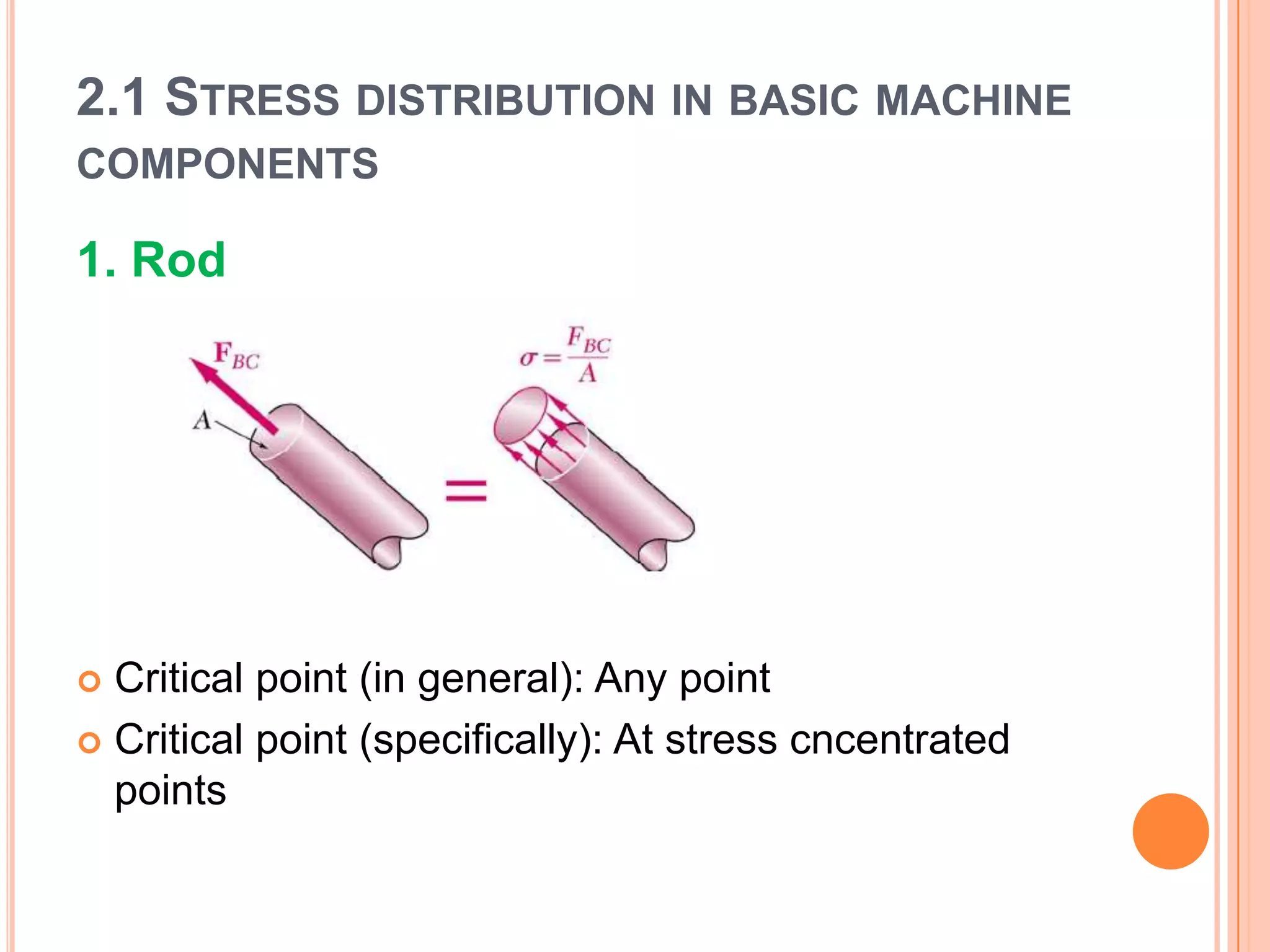
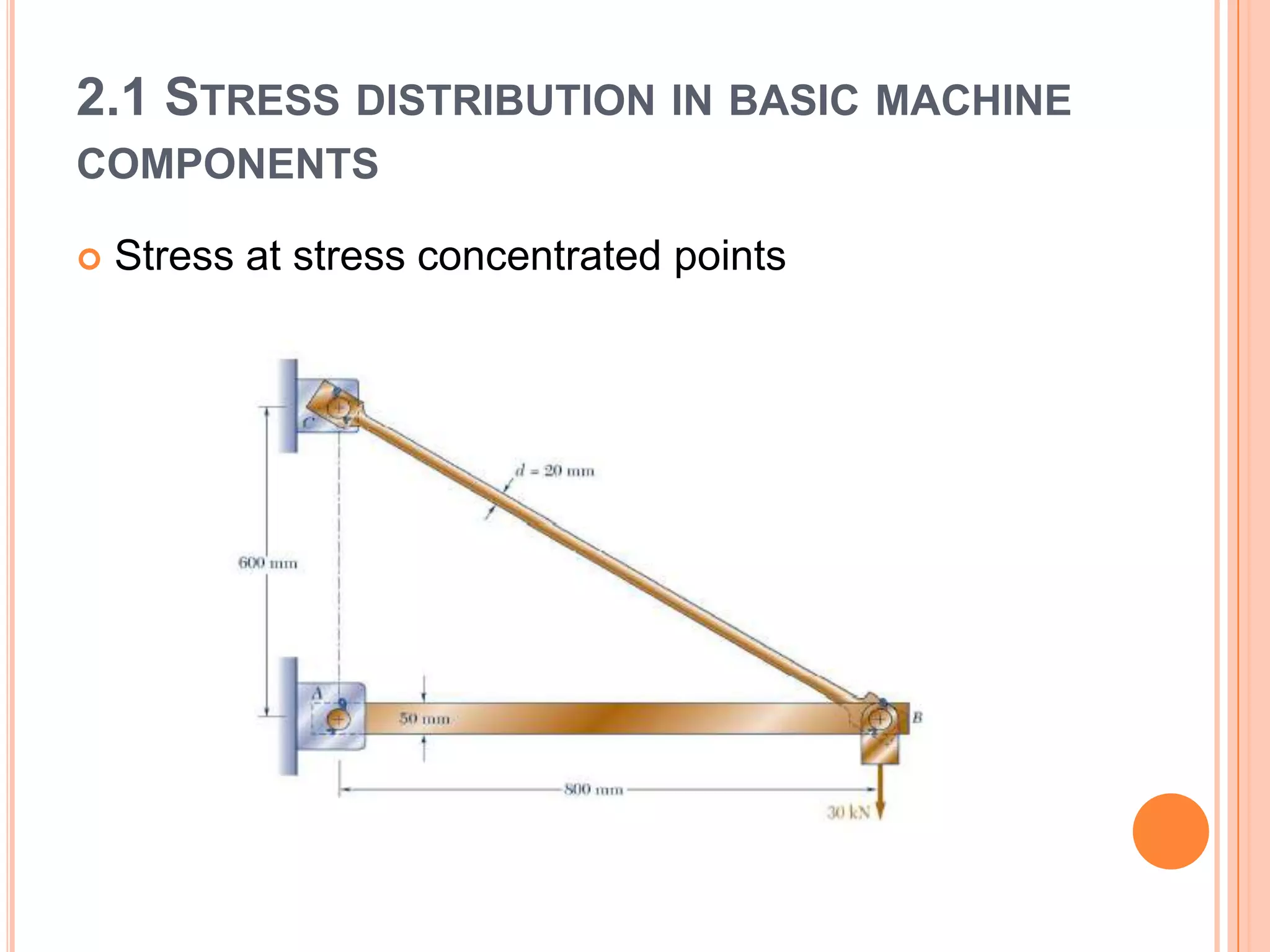
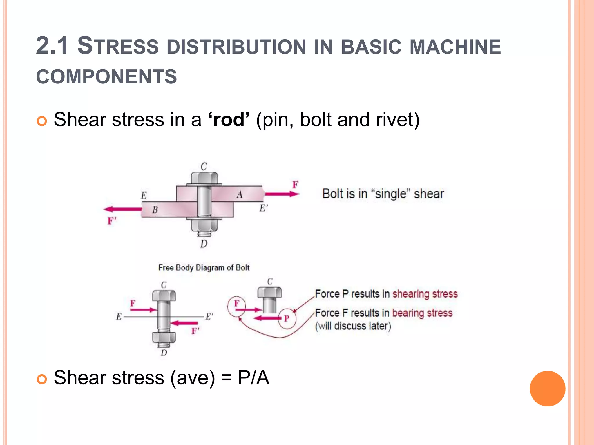
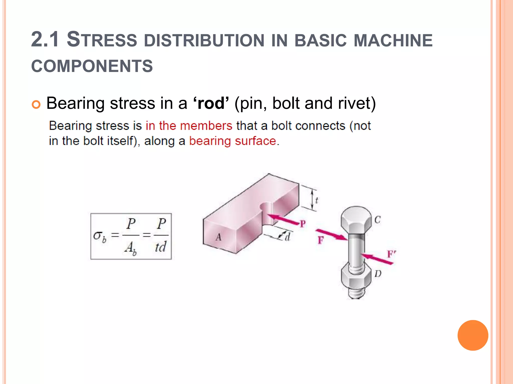
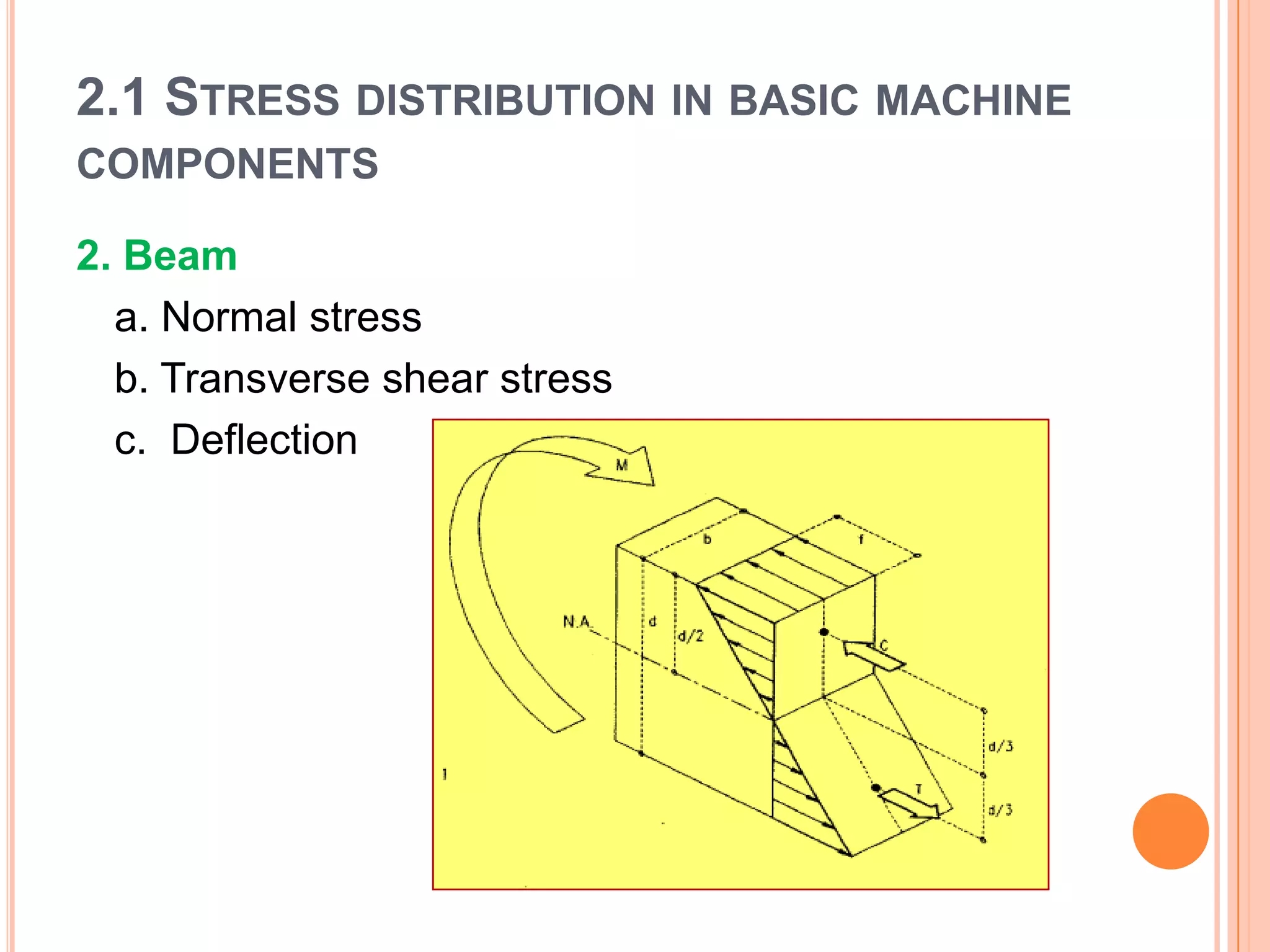
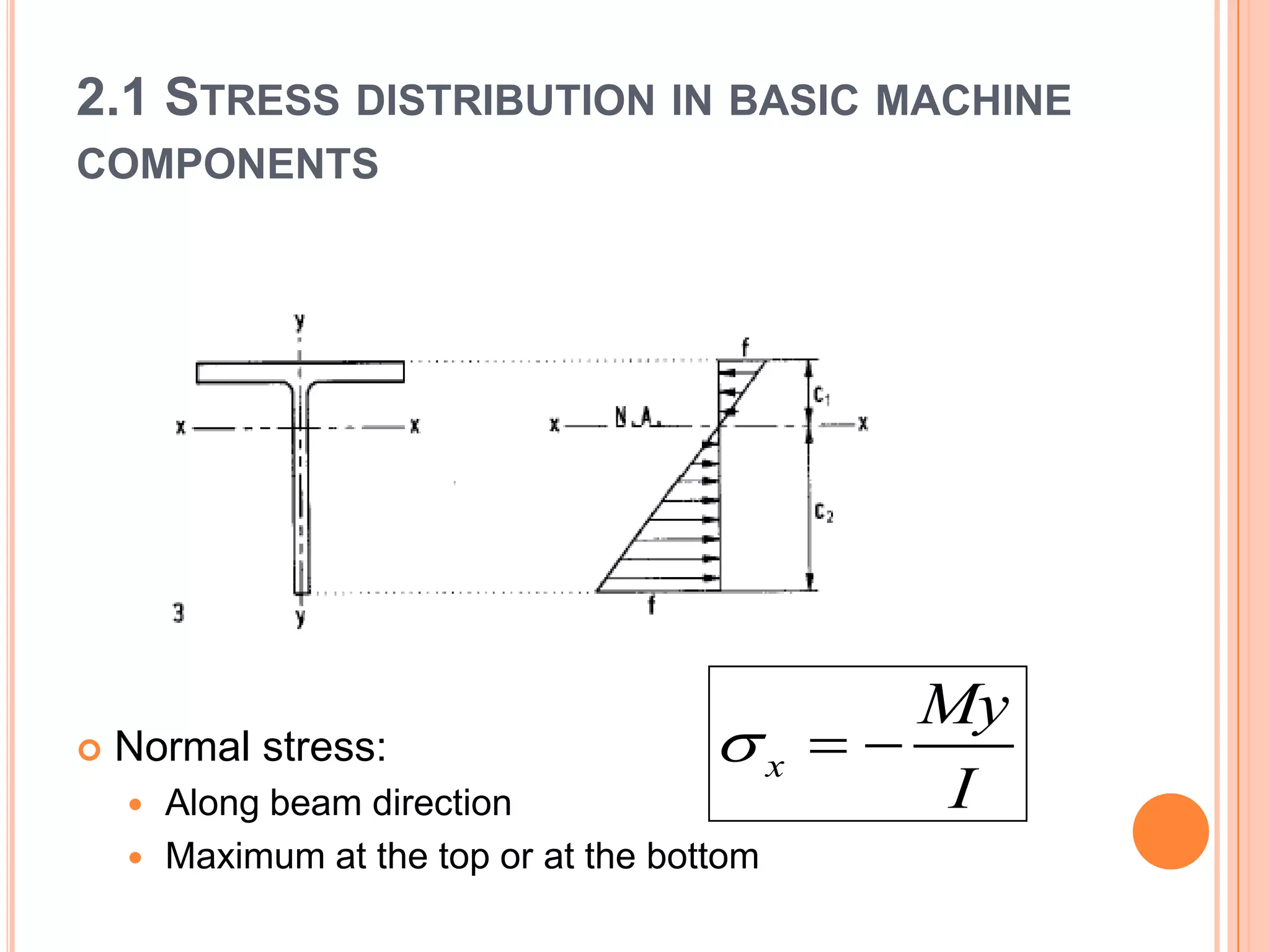
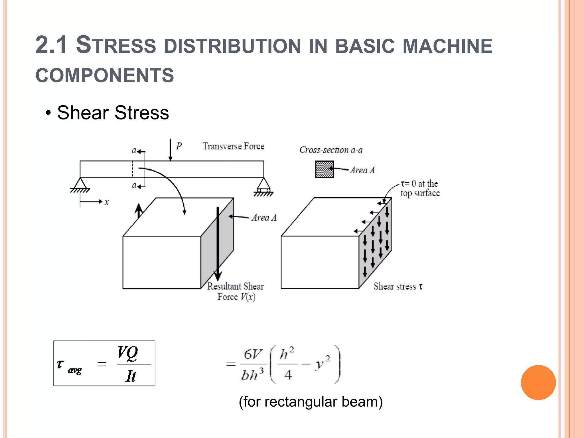
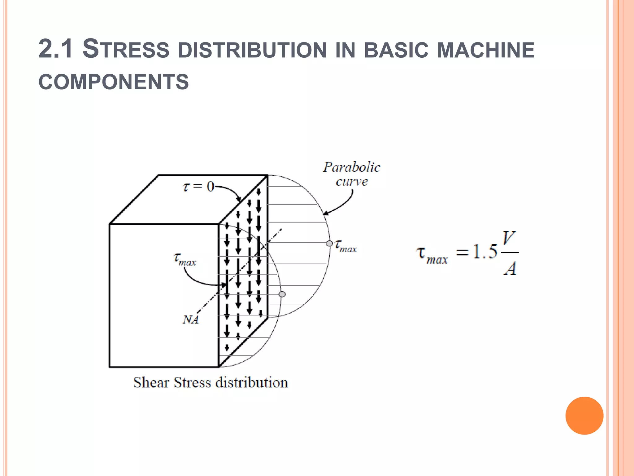
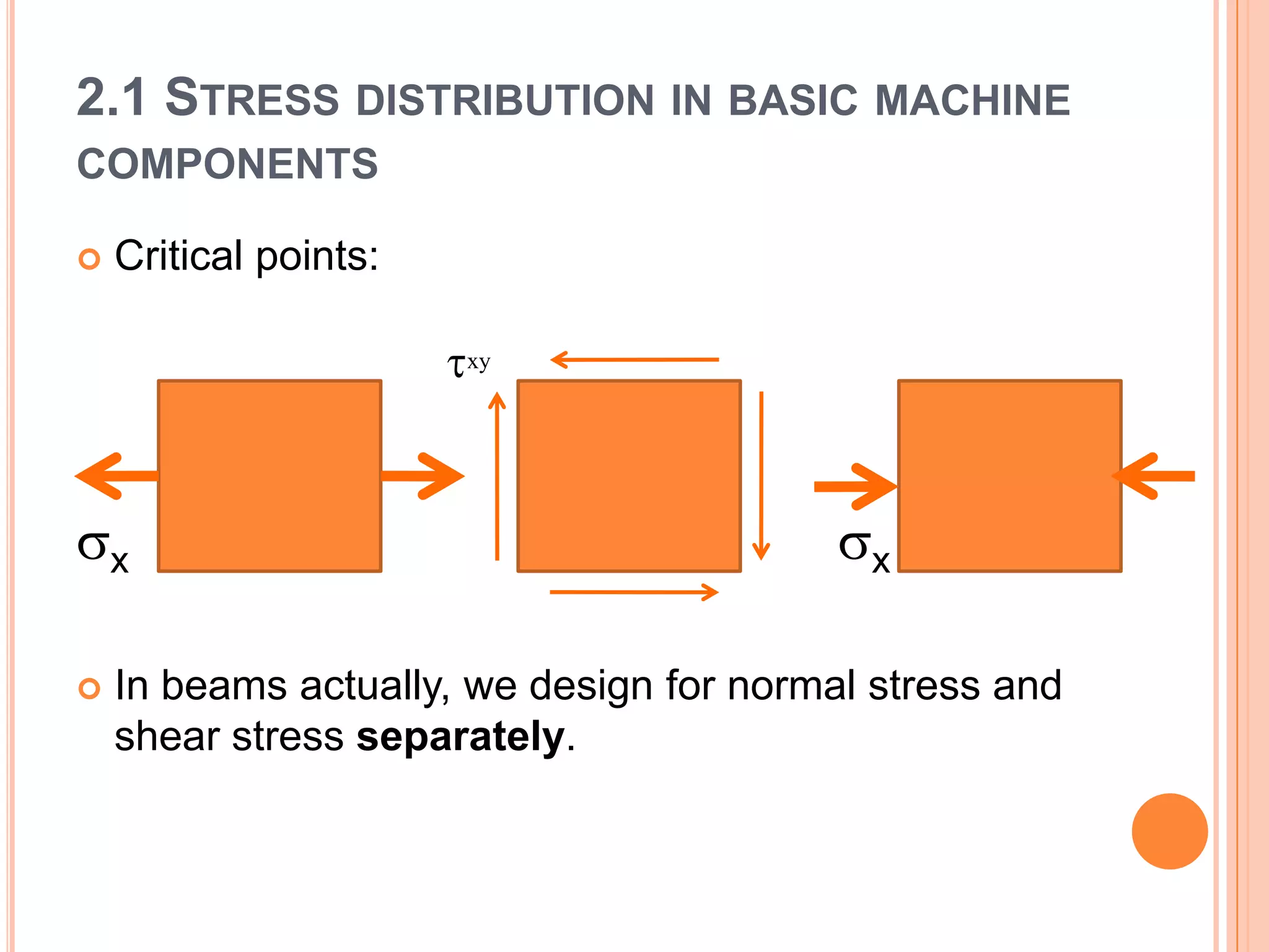
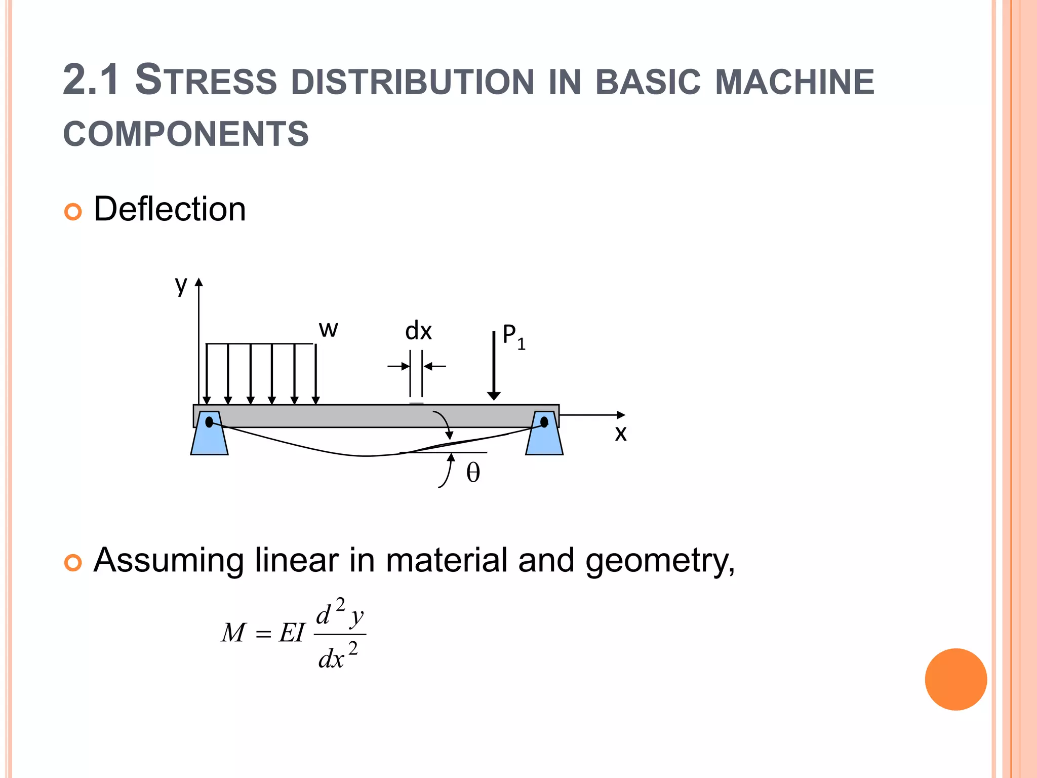
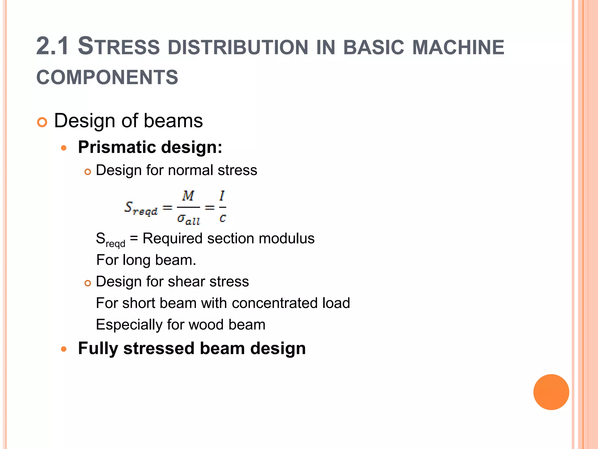
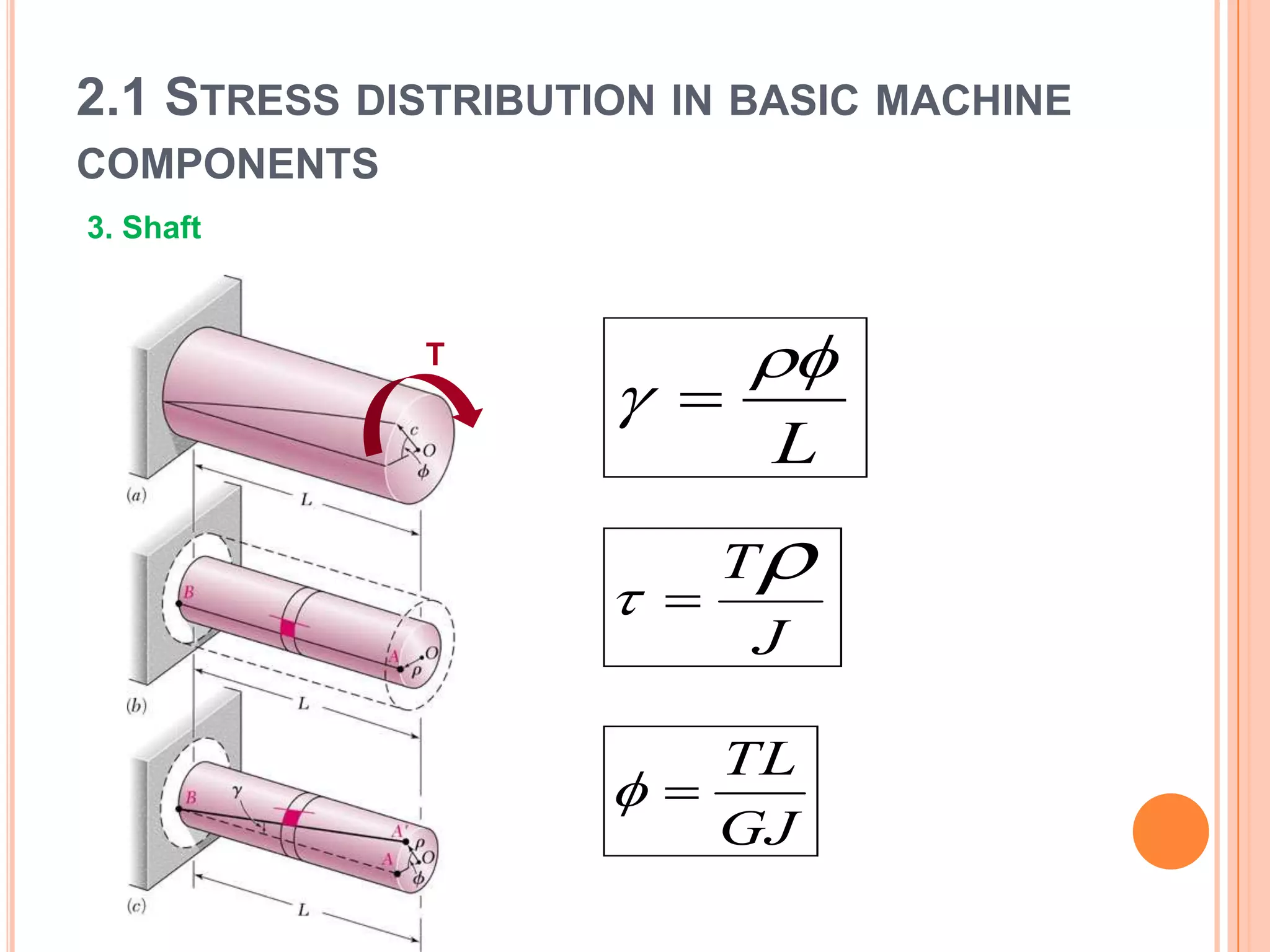
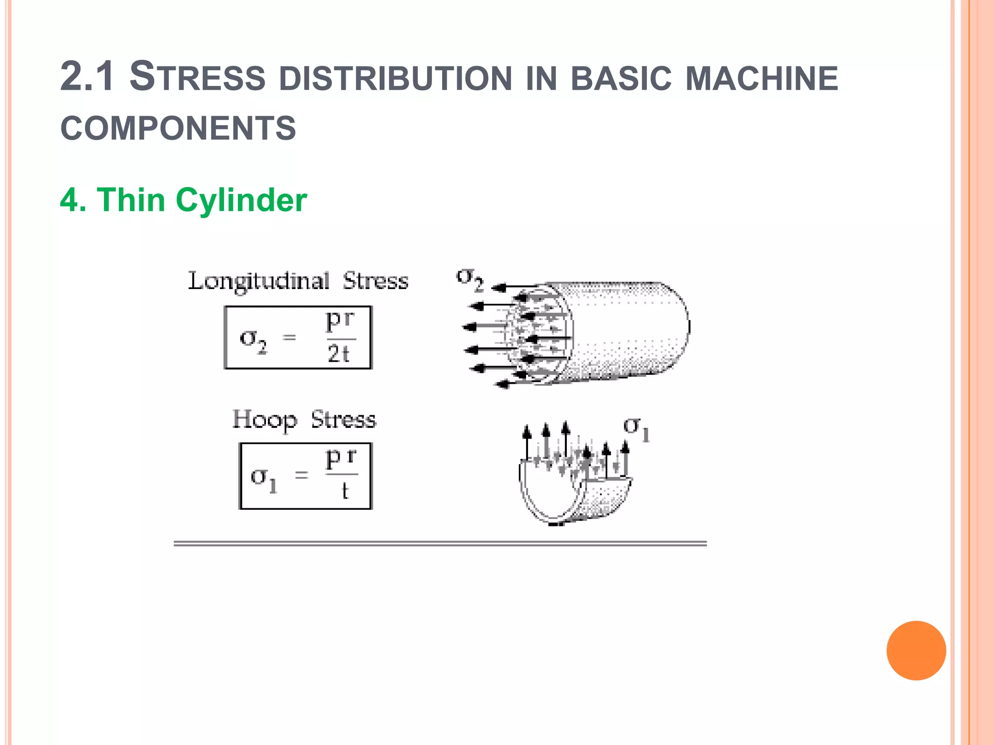
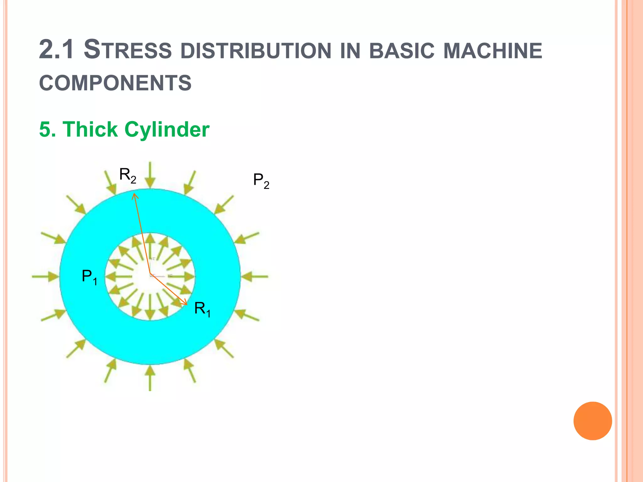
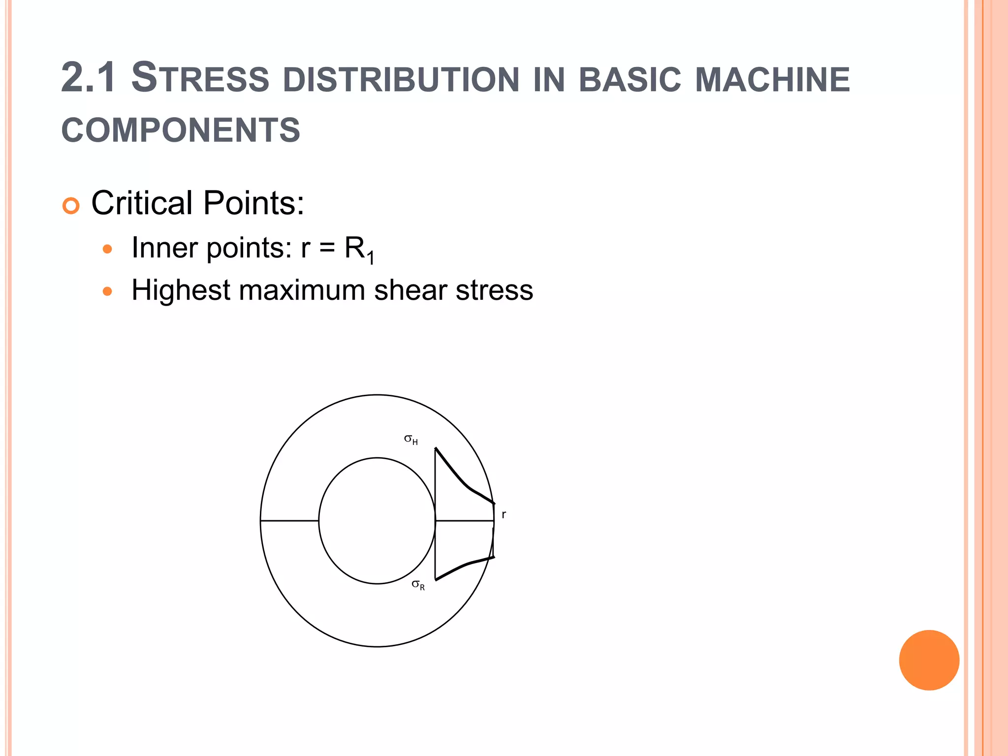
CHAPTER 2 : STATIC LOADING
2.1 STRESS DISTRIBUTION IN BASIC MACHINE
COMPONENTS
1. Rod
 Critical point (in general): Any point
 Critical point (specifically): At stress cncentrated
points
2.1 STRESS DISTRIBUTION IN BASIC MACHINE
COMPONENTS
 Stress at stress concentrated points
2.1 STRESS DISTRIBUTION IN BASIC MACHINE
COMPONENTS
 Shear stress in a ‘rod’ (pin, bolt and rivet)
 Shear stress (ave) = P/A
2.1 STRESS DISTRIBUTION IN BASIC MACHINE
COMPONENTS
 Bearing stress in a ‘rod’ (pin, bolt and rivet)
2.1 STRESS DISTRIBUTION IN BASIC MACHINE
COMPONENTS
2. Beam
a. Normal stress
b. Transverse shear stress
c. Deflection
2.1 STRESS DISTRIBUTION IN BASIC MACHINE
COMPONENTS
 Normal stress:
 Along beam direction
 Maximum at the top or at the bottom
x
My
I
  
2.1 STRESS DISTRIBUTION IN BASIC MACHINE
COMPONENTS
(for rectangular beam)
• Shear Stress
2.1 STRESS DISTRIBUTION IN BASIC MACHINE
COMPONENTS
2.1 STRESS DISTRIBUTION IN BASIC MACHINE
COMPONENTS
 Critical points:
 In beams actually, we design for normal stress and
shear stress separately.
x x
xy
2.1 STRESS DISTRIBUTION IN BASIC MACHINE
COMPONENTS
 Deflection
 Assuming linear in material and geometry,
P1
x
y
w dx

2
2
dx
yd
EIM 
2.1 STRESS DISTRIBUTION IN BASIC MACHINE
COMPONENTS
 Design of beams
 Prismatic design:
 Design for normal stress
Sreqd = Required section modulus
For long beam.
 Design for shear stress
For short beam with concentrated load
Especially for wood beam
 Fully stressed beam design
2.1 STRESS DISTRIBUTION IN BASIC MACHINE
COMPONENTS
T
L

 
GJ
TL

J
T 
3. Shaft
2.1 STRESS DISTRIBUTION IN BASIC MACHINE
COMPONENTS
4. Thin Cylinder
2.1 STRESS DISTRIBUTION IN BASIC MACHINE
COMPONENTS
5. Thick Cylinder
P2
P1
R2
R1
2.1 STRESS DISTRIBUTION IN BASIC MACHINE
COMPONENTS
 Critical Points:
 Inner points: r = R1
 Highest maximum shear stress
r
H
R
2.2 MATERIAL PROPERTIES
 Basic material properties:
 Physical: Density
 Mechanical:
 Young’s modulus
 Shear modulus
 Yield strength
 UTS
 Elongation at break
 Reduction of area
 Poisson’s ratio
 Toughness: modulus of toughness, modulus of resilience
 Hardness (Brinnel, Rockwell, Vickers)
 Impact strength (Izod, Charpy)
 Test:
 Tensile test
 Hardness test
 Impact test
2.2 MATERIAL PROPERTIES
 Tensile test
2.2 MATERIAL PROPERTIES
 Standard codes
1. Society of Automotive Engineers (SAE)
2. British Standards (BS)
3. European standards – (EN)
4. ASTM (UNS)
5. Japanese Industrial Standards (JIS)
6. Germany steel grades (DIN)
7. China steel grades (GB)
2.2 MATERIAL PROPERTIES
 Determine the alloy
content, properties, applications and its code
number.
1. Cast Iron
2. Carbon Steel & Alloys
3. Stainless Steel & Alloys
4. Aluminum & Alloys
5. Magnesium & Alloys
6. Copper &Alloys
7. Titanium & Alloys
8. Zircanium & Alloys
9. Nickel & Alloys
10. Zinc & Alloys
2.3 FAILURE THEORY
 To develop FS of the design
 Static failure theory
 Tresca’s theory
 von Misses’s theory
2.3 FAILURE THEORY
1 1.25 - 1.5
for exceptionally reliable materials used under controllable
conditions and subjected to loads and stresses that can be
determined with certainty - used almost invariably where low
weight is a particularly important consideration
2 1.5 - 2 for well-known materials under reasonably constant environmental
conditions, subjected to loads and stresses that can be determined
readily.
3 2 - 2.5
for average materials operated in ordinary environments and
subjected to loads and stresses that can be determined.
4 2.5 - 3 for less tried materials or for brittle materials under average
conditions of environment, load and stress.
5 3-4 for untried materials used under average conditions of
environment, load and stress.
6 3-4 should also be used with better-known materials that are to be used
in uncertain environments or subject to uncertain stresses.
7
Repeated loads : the factors established in items 1 to 6 are
acceptable but must be applied to the endurance limit (ie. a fatigue
strength ) rather than to the yield strength of the material.
8 Impact forces : the factors given in items 3 to 6 are acceptable, but
an impact factor (the above dynamic magnification factor )
should be included.
9 Brittle materials : where the ultimate strength is used as the
theoretical maximum, the factors presented in items 1 to 6 should
be approximately doubled.
10 Where higher factors might appear desirable, a more thorough
analysis of the problem should be undertaken before deciding on
their use.
based on yield strength - according to Juvinall & Marshek op cit.

Cd chap 2 - static loading

  • 1.
    CHAPTER 2 :STATIC LOADING
  • 2.
    2.1 STRESS DISTRIBUTIONIN BASIC MACHINE COMPONENTS 1. Rod  Critical point (in general): Any point  Critical point (specifically): At stress cncentrated points
  • 3.
    2.1 STRESS DISTRIBUTIONIN BASIC MACHINE COMPONENTS  Stress at stress concentrated points
  • 4.
    2.1 STRESS DISTRIBUTIONIN BASIC MACHINE COMPONENTS  Shear stress in a ‘rod’ (pin, bolt and rivet)  Shear stress (ave) = P/A
  • 5.
    2.1 STRESS DISTRIBUTIONIN BASIC MACHINE COMPONENTS  Bearing stress in a ‘rod’ (pin, bolt and rivet)
  • 6.
    2.1 STRESS DISTRIBUTIONIN BASIC MACHINE COMPONENTS 2. Beam a. Normal stress b. Transverse shear stress c. Deflection
  • 7.
    2.1 STRESS DISTRIBUTIONIN BASIC MACHINE COMPONENTS  Normal stress:  Along beam direction  Maximum at the top or at the bottom x My I   
  • 8.
    2.1 STRESS DISTRIBUTIONIN BASIC MACHINE COMPONENTS (for rectangular beam) • Shear Stress
  • 9.
    2.1 STRESS DISTRIBUTIONIN BASIC MACHINE COMPONENTS
  • 10.
    2.1 STRESS DISTRIBUTIONIN BASIC MACHINE COMPONENTS  Critical points:  In beams actually, we design for normal stress and shear stress separately. x x xy
  • 11.
    2.1 STRESS DISTRIBUTIONIN BASIC MACHINE COMPONENTS  Deflection  Assuming linear in material and geometry, P1 x y w dx  2 2 dx yd EIM 
  • 12.
    2.1 STRESS DISTRIBUTIONIN BASIC MACHINE COMPONENTS  Design of beams  Prismatic design:  Design for normal stress Sreqd = Required section modulus For long beam.  Design for shear stress For short beam with concentrated load Especially for wood beam  Fully stressed beam design
  • 13.
    2.1 STRESS DISTRIBUTIONIN BASIC MACHINE COMPONENTS T L    GJ TL  J T  3. Shaft
  • 14.
    2.1 STRESS DISTRIBUTIONIN BASIC MACHINE COMPONENTS 4. Thin Cylinder
  • 15.
    2.1 STRESS DISTRIBUTIONIN BASIC MACHINE COMPONENTS 5. Thick Cylinder P2 P1 R2 R1
  • 16.
    2.1 STRESS DISTRIBUTIONIN BASIC MACHINE COMPONENTS  Critical Points:  Inner points: r = R1  Highest maximum shear stress r H R
  • 17.
    2.2 MATERIAL PROPERTIES Basic material properties:  Physical: Density  Mechanical:  Young’s modulus  Shear modulus  Yield strength  UTS  Elongation at break  Reduction of area  Poisson’s ratio  Toughness: modulus of toughness, modulus of resilience  Hardness (Brinnel, Rockwell, Vickers)  Impact strength (Izod, Charpy)  Test:  Tensile test  Hardness test  Impact test
  • 18.
  • 19.
    2.2 MATERIAL PROPERTIES Standard codes 1. Society of Automotive Engineers (SAE) 2. British Standards (BS) 3. European standards – (EN) 4. ASTM (UNS) 5. Japanese Industrial Standards (JIS) 6. Germany steel grades (DIN) 7. China steel grades (GB)
  • 20.
    2.2 MATERIAL PROPERTIES Determine the alloy content, properties, applications and its code number. 1. Cast Iron 2. Carbon Steel & Alloys 3. Stainless Steel & Alloys 4. Aluminum & Alloys 5. Magnesium & Alloys 6. Copper &Alloys 7. Titanium & Alloys 8. Zircanium & Alloys 9. Nickel & Alloys 10. Zinc & Alloys
  • 21.
    2.3 FAILURE THEORY To develop FS of the design  Static failure theory  Tresca’s theory  von Misses’s theory
  • 22.
    2.3 FAILURE THEORY 11.25 - 1.5 for exceptionally reliable materials used under controllable conditions and subjected to loads and stresses that can be determined with certainty - used almost invariably where low weight is a particularly important consideration 2 1.5 - 2 for well-known materials under reasonably constant environmental conditions, subjected to loads and stresses that can be determined readily. 3 2 - 2.5 for average materials operated in ordinary environments and subjected to loads and stresses that can be determined. 4 2.5 - 3 for less tried materials or for brittle materials under average conditions of environment, load and stress. 5 3-4 for untried materials used under average conditions of environment, load and stress. 6 3-4 should also be used with better-known materials that are to be used in uncertain environments or subject to uncertain stresses. 7 Repeated loads : the factors established in items 1 to 6 are acceptable but must be applied to the endurance limit (ie. a fatigue strength ) rather than to the yield strength of the material. 8 Impact forces : the factors given in items 3 to 6 are acceptable, but an impact factor (the above dynamic magnification factor ) should be included. 9 Brittle materials : where the ultimate strength is used as the theoretical maximum, the factors presented in items 1 to 6 should be approximately doubled. 10 Where higher factors might appear desirable, a more thorough analysis of the problem should be undertaken before deciding on their use. based on yield strength - according to Juvinall & Marshek op cit.