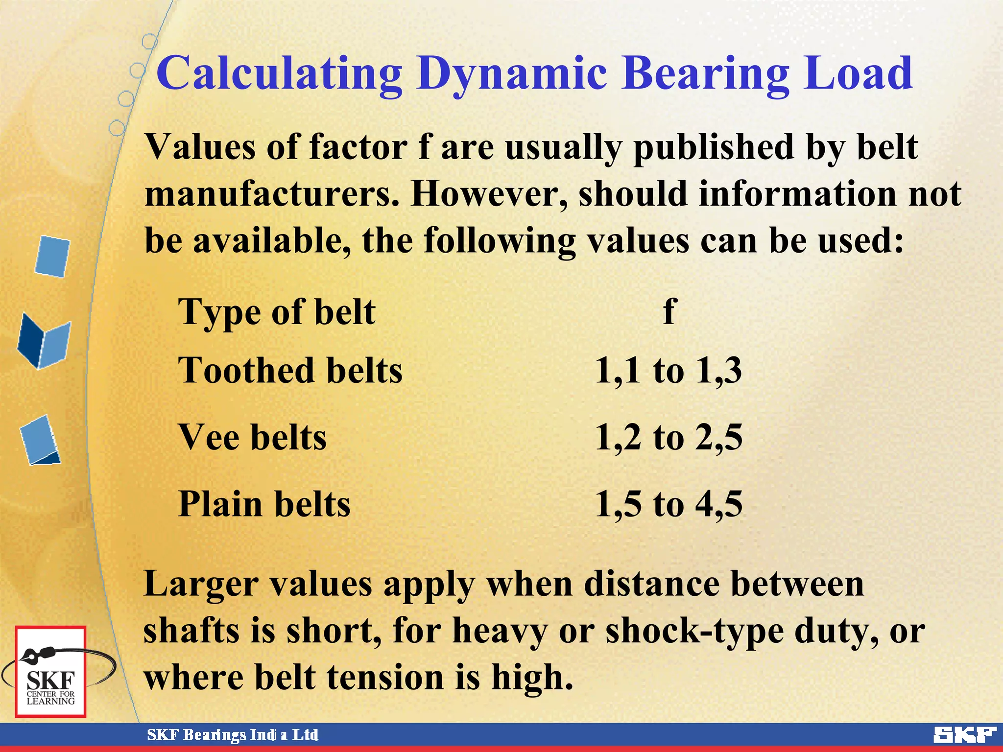
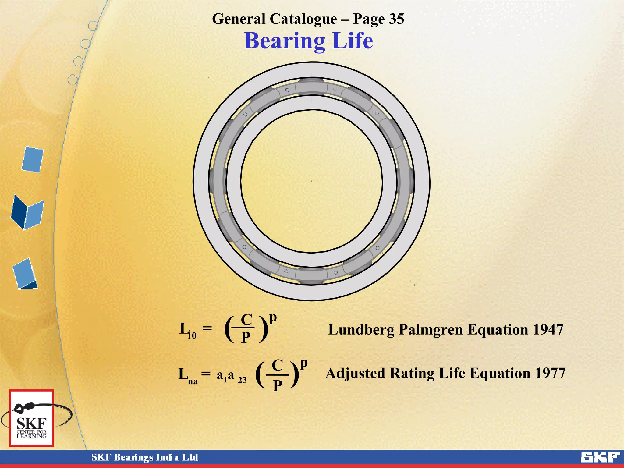
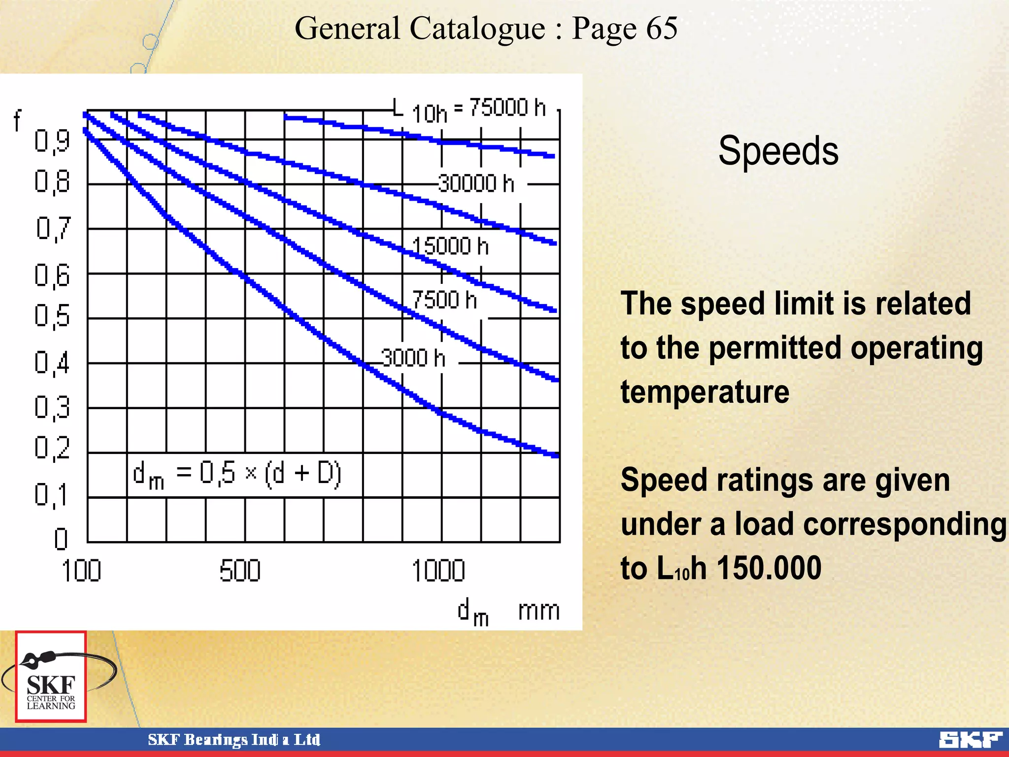
Bearing Life
Bearing Life
Even when bearings are properly applied and maintained,
Eventual failure occurs in the form of Material Fatigue.
Fatigue is a result of sub-surface shear stresses cyclically
applied with initiation immediately below the load carrying
Surface.
Failure begins in the subsurface material and propagates to
the surface as a small undetectable crack. The condition
Gradually matures to Flaking or Spalling of the surface, the
rate dependent upon Load, Speed and Lubrication condition
And worsens as it spreads circumferentially around the ring
Surface.
Bearing Life
Failure mode - Spalling
Bearing Life
Bearing life is defined as the
Number of revolutions
that a bearing undergoes
under a constant load
( Equivalent Dynamic Bearing Load )
before
the first sign of fatigue failure occurs.
Bearing Life
Locating Non-locating
Fr Load
Fa
Fr
Equivalent Dynamic Bearing Load
Calculating Dynamic Bearing Load
G
Kr
Ka
G1
Kr1
I
II
l
a1
FrII
FrI
l
a1
a2
Kr
Ka
III
FrI FrII
Kr1
Stationary Electrical Machine
a2
The following symbols have been used :
W = Power , kW (Output for motors,
input for generators)
n = Speed, rpm
G = Weight of armature and shaft , Kg
G1 = Weight of any load on shaft end , Kg
A = Projected air gap surface
= length x diameter of armature, mm2
Kp = Peripheral Force, Kg
Km= Magnetic pull, Kg
Calculating Dynamic Bearing Load
The following symbols have been used :
Kr = Radial force at CG of armature , Kg
Kr1 = Radial force at shaft end , Kg
Ka = Axial Force , Kg
fk,fd,fb = factors for additional dynamic forces
FrI, = Radial bearing load at position I , Kg
FrII = Radial bearing load at position II, Kg
Fa = Axial bearing load , Kg
a1, a2 = distance from line of action of force to
bearing centre line, mm
Calculating Dynamic Bearing Load
Radial force at the centre of gravity of the armature:
Kr = Km +fb x G
Where
Km = 0.002 A
Calculating Dynamic Bearing Load
Machine Part
fb
Horizontal shaft Vertical shaft
Armature Direct coupled Flexible coupling 1.05 – 1.2 0.2 – 0.5
Solid coupling 1.2 0.5
Belt / Gear / chain drive 1 0
Fly wheel etc, solid coupling 1.05 – 1.2 0.2 – 0.5
The loads acting on the bearing can be calculated
according to the laws of mechanics if the external
forces (e.g. forces from power transmission, work
forces or inertia forces) are known or can be
calculated.
When calculating the load components for a single
bearing, the shaft is considered as being a beam
resting on rigid, moment-free supports for the sake
of simplification.
Calculating Dynamic Bearing Load
Elastic deformations in the bearing, the
housing or the machine frame are not
considered, nor are the moments produced in
the bearing as a result of shaft deflection.
These simplifications are necessary if a bearing
arrangement is to be calculated using readily
available aids such as pocket calculators.
The standardized methods for calculating basic
load ratings and equivalent bearing loads are
based on similar assumptions.
Calculating Dynamic Bearing Load
It is possible to calculate bearing loads based
on the theory of elasticity without making the
above assumptions, but this requires the use of
a powerful computer and lengthy complex
programs.
The bearings, shaft and housing are considered
as resilient components of a system.
Calculating Dynamic Bearing Load
Those external forces which arise, for example,
from the inherent weight of the shaft and the
components which it carries, or from the weight
of a vehicle, and the other inertia forces are either
known or can be calculated. However, when
determining the work forces (rolling forces,
cutting forces in machine tools etc.), shock forces
and additional dynamic forces, e.g. as a result of
unbalance, it is often necessary to rely on
estimations based on experience gained with
similar machines or bearing arrangements.
Calculating Dynamic Bearing Load
Gear trains :
With a gear train, the theoretical tooth forces can
be calculated from the power transmitted and the
design characteristics of the gear teeth. However,
there are additional dynamic forces, produced
either in the gear itself or by the input drive or
power take-off.
Additional dynamic forces in gears result from
errors of form of the teeth and from unbalance of
the rotating components.
Calculating Dynamic Bearing Load
Gear trains :
Because of the requirements for quiet running,
gears are made to high standards of accuracy and
these forces are generally so small that they can be
neglected when making bearing calculations.
Additional forces arising from the type and mode
of operation of the machines coupled to the gear
can only be determined when the operating
conditions are known.
Calculating Dynamic Bearing Load
Gear trains :
Their influence on the rating lives of the bearings
is considered using an "operation" factor which
takes into account shock loads and the efficiency
of the gear.
Values of this factor for different operating
conditions can usually be found in information
published by the gear manufacturer.
Calculating Dynamic Bearing Load
For a quick estimation, one can use the formula:
Kr1 = fk * fd * Kp + G1 for Horizontal shafts
= fk * fd * Kp for Vertical shafts
Where
Kr1 = Radialforce on shaft end, Kg
fk , fd = factors for additional dynamic forces
Kp = Peripheral force, Kg
Calculating Dynamic Bearing Load
No.of
engagement
Quality of gear wheel fk
1
Precision teeth ( error < 25µm) 1.05 – 1.1
Commercial planed or milled teeth, also sprockets
( error 25 – 125 µm)
1.1 – 1.3
Cast teeth ( error > 125 µm) 1.5 – 2.2
2
Precision teeth 0.6 – 0.7
Commercial planed or milled teeth 0.7 – 0.8
Factor fk for additional dynamic forces for
calculating the actual tooth force
The lower value applies to low tooth speeds
v 1.85M/sec
Calculating Dynamic Bearing Load
Factor fd for additional dynamic forces arising
from mechanisms coupled to gearing
Types of Machines fd
Electric Machines ,Turbines 1.0 – 1.1
Traction Motors 1.1 – 1.5
Conveying Equipment 1.0 – 2.5
Mining & Construction Eqpt 1.1 - 2.2
Agricultural & Food Processing Machineries 1.1 – 2.0
Paper making Machines 1.0 – 1.1
Chippers 1.5 – 2.0
Shaking Equipment 1.5 – 2.5
Drilling / Milling / Grinding Machines 1.1 – 1.3
Frame Saws 1.2 – 1.3
Machine Tools with reciprocating motions 1.4 – 1.6
Calculating Dynamic Bearing Load
Belt drives :
For belt drives it is necessary to take into account
the effective belt pull (circumferential force)
which is dependent on the transmitted torque,
when calculating bearing loads.
The belt pull must be multiplied by a factor
which is dependent on type of belt, its preload,
belt tension and any additional dynamic forces.
Calculating Dynamic Bearing Load
For a quick estimation, one can use the formula:
Kr1 = f* Kp + G1 for Horizontal shafts
= f * Kp for Vertical shafts
Where
Kr1 = Radial force on shaft end, Kg
f = factor for belt pull
Kp = Peripheral force, Kg
Calculating Dynamic Bearing Load
Values of factor f are usually published by belt
manufacturers. However, should information not
be available, the following values can be used:
Type of belt f
Toothed belts 1,1 to 1,3
Vee belts 1,2 to 2,5
Plain belts 1,5 to 4,5
Larger values apply when distance between
shafts is short, for heavy or shock-type duty, or
where belt tension is high.
Calculating Dynamic Bearing Load
Direct drive through Flexible coupling :
For a quick estimation, one can use the formula:
Kr1 = 8.17*  ( W / n ) + G1
Where
Kr1 = Radial force on shaft end, Kg
W = Power , Watts
n = Speed, rpm
G1 = Weight of half coupling , Kg
Calculating Dynamic Bearing Load
Thrust Forces :
The thrust load on the locating bearing is :
Fa = Ka in Horizontal machines
And
Fa = G + G1 +Ka in Vertical machines
Where
Ka = External thrust load, Kg
G = Weight of rotor , Kg
G1 = Weight at shaft end e.g.,coupling etc, Kg
Calculating Dynamic Bearing Load
Ka could be the
 Axial component of gear tooth forces
 Pressure from a pump
 Pressure from a turbine
 Thrust load from certain types of flexible
couplings, brakes etc.
For Vertical direct coupled turbines,
Ka = weight of impeller etc. + water load.
Thrust force arising out of magnetic unbalance in
an electrical machine may be ignored.
Bearing Life
Equivalent Dynamic Bearing Load
P = X Fr + Y Fa
Where :
X = Radial Load Factor
Y = Axial Load Factor
General Catalogue – Page 49
Bearing Life
Radial & Axial Load Factors
DGBB : General Catalogue Pages 184 - 185
P = Fr if Fa/Fr </= e
P = X Fr + Y Fa if Fa/Fr > e
C0 is given in Pages 186 – 253
e is given in Page 185
Bearing Life
Radial & Axial Load Factors
SABB : General Catalogue Page 261
P = Fr + Y1 Fa if Fa/Fr </= e
P = 0.65 Fr + Y2 Fa if Fa/Fr > e
Y1, Y2 & e are given in Pages 264 – 283
Bearing Life
Radial & Axial Load Factors
ACBB : General Catalogue Page 292
Single Bearing / Tandem :
P = Fr if Fa/Fr </= 1.14
P = 0.35 Fr + 0.57 Fa if Fa/Fr > 1.14
Paired X or O :
P = Fr + 0.55 Fa if Fa/Fr </= 1.14
P = 0.57 Fr + 0.93 Fa if Fa/Fr > 1.14
Bearing Life
Radial & Axial Load Factors
DRACBB : General Catalogue Page 311
P = Fr + 0.73 Fa if Fa/Fr </= 0.86
P = 0.62 Fr + 1.17 Fa if Fa/Fr > 0.86
Bearing Life
Radial & Axial Load Factors
CRB : General Catalogue Page 336
P = Fr
For Flanged CRB,
P = Fr if Fa/Fr </= e
P = 0.92 Fr + Y Fa if Fa/Fr > e
Y& e are given in Page 336
Bearing Life
Radial & Axial Load Factors
SRB : General Catalogue Page 467
P = Fr + Y1 Fa if Fa/Fr </= e
P = 0.67 Fr + Y2 Fa if Fa/Fr > e
Y1, Y2 & e are given in Pages 470 – 511
Bearing Life
Radial & Axial Load Factors
SRTRB : General Catalogue Page 520 - 521
P = Fr if Fa/Fr </= e
P = 0.4 Fr + Y Fa if Fa/Fr > e
Y& e are given in Pages 526 – 585
Bearing Life
Radial & Axial Load Factors
Paired TRB : General Catalogue Page 589
P = Fr + Y1 Fa if Fa/Fr </= e
P = 0.67 Fr + Y2 Fa if Fa/Fr > e
Y1, Y2 & e are given in Pages 590 – 593
Bearing Life
Radial & Axial Load Factors
ThBB / CRThB : General Catalogue Page 597/622
P = Fa
Bearing Life
Radial & Axial Load Factors
SRThB : General Catalogue Page 646
P = Fa + 1.2 Fr if Fr </= 0.55Fa
P = 0.88(Fa + 1.2 Fr ) if adjustable
assembly &
Fr </= 0.55Fa
Bearing Life
( )C p
L =10 P
Lundberg Palmgren Equation 1947( )C p
L =10 P
Lundberg Palmgren Equation 1947
General Catalogue – Page 35
Bearing Life
( )C p
L =10 P
Lundberg Palmgren Equation 1947
( )C p
L =na
P
a1a 23
Adjusted Rating Life Equation 1977
General Catalogue – Page 35
Bearing Life
( )C p
L =10 P
Lundberg Palmgren Equation 1947
( )C p
L =na
P
a1a 23
Adjusted Rating Life Equation 1977
New SKF Life Equation 1989L =naa
a1a SKF
( )C p
P
General Catalogue – Page 40
Bearing Selection
Bearings are selected based on:
 Load
 Speed
 Temperature
 Environment
 Life expectancy
Selection of bearings
Some aspects to be considered
Available space Misalignment
Speed Life
Load/Direction Operating conditions
L =10
( )C
P
p
Load carrying capacity
is expressed as the basic
dynamic load rating
of different bearing types having the same bore and outside diameters
Speed ratings speed limit
0 r/min
Oil lubrication
speed rating
Grease lubrication
speed rating
Bearing speed
limit
=
Factors influencing speed capability
Increases speed
 Low loads
 High accuracy
 Good sliding properties
of cage guiding surface
 Correct clearance
 Optimised lubrication
 Effective cooling
Reduces speed
 High loads
 Poor accuracy
 Excess of lubricant
 Lack of lubricant
 Excessive lubricant
viscosity
 Poor cooling
Basic Terminologies :
1. Static Load
1. Dynamic Load
1. Life Requirement
General Catalogue – Page 27
Basic dynamic load rating
ISO dynamic load rating
C = Load that gives a basic rating
life of 1 000 000 revolutions
C
Basic Dynamic Load Rating
Basic Dynamic Load Rating of a Radial Ball Bearing is :
C = fc (i cos α)0.7
z 2/3
F (Dw)
Where
C = Basic Dynamic Load Rating , Kg
fc = Factor for calculating C
i = Number of rows of balls
z = Number of rolling elements per row
α = Contact angle, Degrees
Dw = Diameter of the balls, mm
F (Dw) = Dw
1.8
whenDw 25.4 mm
= 3.647 Dw
1.4
whenDw >25.4 mm
Basic Dynamic Load Rating
Basic Dynamic Load Rating of
Single Row Thrust Ball Bearing (α900
) is :
C = fc (cos α)0.7
tan α z 2/3
F (Dw)
Where
C = Basic Dynamic Load Rating , Kg
fc = Factor for calculating C
z = Number of rolling elements per row
α = Contact angle, Degrees
Dw = Diameter of the balls, mm
F (Dw) = Dw
1.8
whenDw 25.4 mm
= 3.647 Dw
1.4
whenDw >25.4 mm
Basic Dynamic Load Rating
Basic Dynamic Load Rating of
Single Row Thrust Ball Bearing (α = 900
) is :
C = fc z 2/3
F (Dw)
Where
C = Basic Dynamic Load Rating , Kg
fc = Factor for calculating C
z = Number of rolling elements per row
Dw = Diameter of the balls, mm
F (Dw) = Dw
1.8
whenDw 25.4 mm
= 3.647 Dw
1.4
whenDw >25.4 mm
Basic Dynamic Load Rating
Basic Dynamic Load Rating of a Radial Roller Bearing is :
C = fc (i la cos α) 7/9
z 3/4
Dw
29/27
Where
C = Basic Dynamic Load Rating , Kg
i = Number of rows of rollers
la = Effective length of rollers, mm
Dw = Diameter of the rollers, mm
z = Number of rolling elements per row
α = Contact angle, Degrees
Basic Dynamic Load Rating
Basic Dynamic Load Rating of
Single Row Thrust Roller Bearing (α900
) is :
C = fc (la cos α)7/9
tan α z 3/4
Dw
29/27
Where
C = Basic Dynamic Load Rating , Kg
fc = Factor for calculating C
la = Effective length of rollers, mm
z = Number of rolling elements per row
α = Contact angle, Degrees
Dw = Diameter of the rollers, mm
Basic Dynamic Load Rating
Basic Dynamic Load Rating of
Single Row Thrust Roller Bearing (α = 900
) is :
C = fc la
7/9
z 3/4
Dw
29/27
Where
C = Basic Dynamic Load Rating , Kg
fc = Factor for calculating C
la = Effective length of rollers, mm
z = Number of rolling elements per row
Dw = Diameter of the rollers, mm
Basic static load rating
ISO basic load rating Co
corresponds to a stress that
gives permanent deformation
of 0,0001 of the rolling
element diameter
Basic Static Load Rating
Basic Static Load Rating of a Radial Ball Bearing is :
C0 = 0.22 ko i z Dw
2
Cosα
Where
C0 = Basic Static Load Rating , Kg
k0 = Factor for calculating C0
i = Number of rows of balls
z = Number of rolling elements per row
α = Contact angle, Degrees
Dw = Diameter of the balls, mm
Basic Static Load Rating
Basic Static Load Rating of a Radial Roller Bearing is :
C0 = 0.22 ko i z Dw la Cosα
Where
C0 = Basic Static Load Rating , Kg
k0 = Factor for calculating C0
i = Number of rows of rollers
z = Number of rolling elements per row
α = Contact angle, Degrees
Dw = Diameter of the rollers, mm
la = Effective length of rollers, mm
Basic Static Load Rating
Basic Static Load Rating of
Single row thrust Ball Bearing is :
C0 = ko z Dw
2
Sinα
Where
C0 = Basic Static Load Rating , Kg
k0 = Factor for calculating C0
z = Number of rolling elements per row
α = Contact angle, Degrees
Dw = Diameter of the balls, mm
Basic Static Load Rating
Basic Static Load Rating of
Multi row thrust Ball Bearing (α = 900
) is :
C0 = ko Σ z Dw
2
Where
C0 = Basic Static Load Rating , Kg
k0 = Factor for calculating C0
z = Number of rolling elements per row
Dw = Diameter of the balls, mm
Basic Static Load Rating
Basic Static Load Rating of
Single row thrust roller bearing is :
C0 = ko z Dw la Sinα
Where
C0 = Basic Static Load Rating , Kg
k0 = Factor for calculating C0
z = Number of rolling elements per row
α = Contact angle, Degrees
Dw = Diameter of the rollers, mm
la = Effective length of rollers, mm
Basic Static Load Rating
Basic Static Load Rating of
Multi row thrust roller bearing (α = 900
) is :
C0 = ko Σ z Dw la
Where
C0 = Basic Static Load Rating , Kg
k0 = Factor for calculating C0
z = Number of rolling elements per row
α = Contact angle, Degrees
Dw = Diameter of the rollers, mm
la = Effective length of rollers, mm
Bearing Life considerations vary
depending on :
Type of Rolling Element
1. Ball
2. Roller
a. Cylindrical
b. Needle
c. Tapered
d. Spherical
I Symmetrical
II Asymmetrical
Different Applications require
different Life:
1. Hand Tool
2. Elevator
3. Machine Tools
4. Industrial Fans
5. Pumps
6. Water Circulating Pumps
Load carrying capacity
Basic dynamic load rating C
L10 = basic rating life, millions of
revolutions
C = basic dynamic load rating, N
P = equivalent dynamic bearing load, N
p = exponent of the life equation
With the load P = C
the L life will be 1 million revolutions10
Basic static load rating C 0
P0
P0
P
P
The ISO life equation
s0 = static safety factor
P0 = equivalent static bearing load, N
C0 = basic static load rating, N
With the load P = C0
the static safety factor s0 will be 1
The static safety factor
s =0
C0
P0
( )C
L =10 P
p
General Catalogue – Page 53
Equivalent Static Bearing Load
P0 = X0 Fr + Y0 Fa
Where :
X0 = Static Radial Load Factor
Y0 = Static Axial Load Factor
General Catalogue – Page 52
( )C p
L =10 P Lundberg Palmgren Equation 1947
Bearing Life
L10 = Basic Rating Life, Millions of Revolutions
C = Basic Dynamic Load Rating , N
P = Equivalent Dynamic Bearing Load, N
p = Exponent of the life equation
= 3 for ball bearings
= 10/3 for roller bearings
L =
10h
( )C p
P Lundberg Palmgren Equation 1947
Bearing Life
L10h = Basic Rating Life, Operating Hours
C = Basic Dynamic Load Rating , N
P = Equivalent Dynamic Bearing Load, N
p = Exponent of the life equation
= 3 for ball bearings
= 10/3 for roller bearings
n = Rotational Speed rpm
1 000 000
60 n
General Catalogue – Page 34
General Catalogue – Page 33
Adjusted Rating Life Equation
( )C p
L =
na P
a1a 23
Lna = Adjusted Rating Life, Millions of Revolutions
a1 = Life Adjustment Factor for Reliability
a23 = Life Adjustment Factor for Material
and Lubrication
Reliability Factor a1
General Catalogue – Page 35
Material & Lubrication Factor a23
General Catalogue – Page 39
New SKF Life Equation 1989
L =
naa
a1a SKF ( )C p
P
Lnaa = Adjusted Rating Life to new life
theory, Millions of Revolutions
a1 = Life Adjustment Factor for Reliability
aSKF = Life Adjustment Factor for Material,
Lubrication, Minimum load and
Contamination
General Catalogue – Page 41
General Catalogue – Page 42
General Catalogue – Page 43
General Catalogue – Page 44
General Catalogue : Page 24 - 25
Bearing Life
C
P
L =10
( )
p
L = a anaa 1 SKF
( )C
P
p
ISO
Finite life
Load P
Life
The SKF New Life Theory
Infinite life
Load P
Life
Service life:
This is the actual life achieved by the bearing before it fails.
PU
Bearing calculations
Catalogue methods
Advanced methods
Manual calculations Computer calculations
CADalog is a
computerised
version of the
General Catalogue
L =10
( )pC
P
L = a ana 1 23
( )pC
P
L = a anaa 1 SKF
( )pC
P
SKF application engineers have a comprehensive library of
sophisticated computer programs at their disposal. These programs
can be used to determine more accurately the bearing size and life.
General
Catalogue
CADalog
Friction Under certain conditions the frictional
moment can be calculated with sufficient
accuracy
M = 0,5 . µ . F . d
M = frictional moment (Nmm)
µ = coefficient of friction
F = bearing load (N)
d = bearing bore diameter (mm)
General Catalogue : Page 56
Speeds
The speed limit is related
to the permitted operating
temperature
Speed ratings are given
under a load corresponding
to L10h 150.000
General Catalogue : Page 65

1.2 bearing life

  • 1.
  • 2.
    Bearing Life Even whenbearings are properly applied and maintained, Eventual failure occurs in the form of Material Fatigue. Fatigue is a result of sub-surface shear stresses cyclically applied with initiation immediately below the load carrying Surface. Failure begins in the subsurface material and propagates to the surface as a small undetectable crack. The condition Gradually matures to Flaking or Spalling of the surface, the rate dependent upon Load, Speed and Lubrication condition And worsens as it spreads circumferentially around the ring Surface.
  • 3.
  • 4.
    Bearing Life Bearing lifeis defined as the Number of revolutions that a bearing undergoes under a constant load ( Equivalent Dynamic Bearing Load ) before the first sign of fatigue failure occurs.
  • 5.
    Bearing Life Locating Non-locating FrLoad Fa Fr Equivalent Dynamic Bearing Load
  • 6.
    Calculating Dynamic BearingLoad G Kr Ka G1 Kr1 I II l a1 FrII FrI l a1 a2 Kr Ka III FrI FrII Kr1 Stationary Electrical Machine a2
  • 7.
    The following symbolshave been used : W = Power , kW (Output for motors, input for generators) n = Speed, rpm G = Weight of armature and shaft , Kg G1 = Weight of any load on shaft end , Kg A = Projected air gap surface = length x diameter of armature, mm2 Kp = Peripheral Force, Kg Km= Magnetic pull, Kg Calculating Dynamic Bearing Load
  • 8.
    The following symbolshave been used : Kr = Radial force at CG of armature , Kg Kr1 = Radial force at shaft end , Kg Ka = Axial Force , Kg fk,fd,fb = factors for additional dynamic forces FrI, = Radial bearing load at position I , Kg FrII = Radial bearing load at position II, Kg Fa = Axial bearing load , Kg a1, a2 = distance from line of action of force to bearing centre line, mm Calculating Dynamic Bearing Load
  • 9.
    Radial force atthe centre of gravity of the armature: Kr = Km +fb x G Where Km = 0.002 A Calculating Dynamic Bearing Load
  • 10.
    Calculating Dynamic BearingLoad Machine Part fb Horizontal shaft Vertical shaft Armature Direct coupled Flexible coupling 1.05 – 1.2 0.2 – 0.5 Solid coupling 1.2 0.5 Belt / Gear / chain drive 1 0 Fly wheel etc, solid coupling 1.05 – 1.2 0.2 – 0.5
  • 11.
    The loads actingon the bearing can be calculated according to the laws of mechanics if the external forces (e.g. forces from power transmission, work forces or inertia forces) are known or can be calculated. When calculating the load components for a single bearing, the shaft is considered as being a beam resting on rigid, moment-free supports for the sake of simplification. Calculating Dynamic Bearing Load
  • 12.
    Calculating Dynamic BearingLoad Elastic deformations in the bearing, the housing or the machine frame are not considered, nor are the moments produced in the bearing as a result of shaft deflection. These simplifications are necessary if a bearing arrangement is to be calculated using readily available aids such as pocket calculators. The standardized methods for calculating basic load ratings and equivalent bearing loads are based on similar assumptions.
  • 13.
    Calculating Dynamic BearingLoad It is possible to calculate bearing loads based on the theory of elasticity without making the above assumptions, but this requires the use of a powerful computer and lengthy complex programs. The bearings, shaft and housing are considered as resilient components of a system.
  • 14.
    Calculating Dynamic BearingLoad Those external forces which arise, for example, from the inherent weight of the shaft and the components which it carries, or from the weight of a vehicle, and the other inertia forces are either known or can be calculated. However, when determining the work forces (rolling forces, cutting forces in machine tools etc.), shock forces and additional dynamic forces, e.g. as a result of unbalance, it is often necessary to rely on estimations based on experience gained with similar machines or bearing arrangements.
  • 15.
    Calculating Dynamic BearingLoad Gear trains : With a gear train, the theoretical tooth forces can be calculated from the power transmitted and the design characteristics of the gear teeth. However, there are additional dynamic forces, produced either in the gear itself or by the input drive or power take-off. Additional dynamic forces in gears result from errors of form of the teeth and from unbalance of the rotating components.
  • 16.
    Calculating Dynamic BearingLoad Gear trains : Because of the requirements for quiet running, gears are made to high standards of accuracy and these forces are generally so small that they can be neglected when making bearing calculations. Additional forces arising from the type and mode of operation of the machines coupled to the gear can only be determined when the operating conditions are known.
  • 17.
    Calculating Dynamic BearingLoad Gear trains : Their influence on the rating lives of the bearings is considered using an "operation" factor which takes into account shock loads and the efficiency of the gear. Values of this factor for different operating conditions can usually be found in information published by the gear manufacturer.
  • 18.
    Calculating Dynamic BearingLoad For a quick estimation, one can use the formula: Kr1 = fk * fd * Kp + G1 for Horizontal shafts = fk * fd * Kp for Vertical shafts Where Kr1 = Radialforce on shaft end, Kg fk , fd = factors for additional dynamic forces Kp = Peripheral force, Kg
  • 19.
    Calculating Dynamic BearingLoad No.of engagement Quality of gear wheel fk 1 Precision teeth ( error < 25µm) 1.05 – 1.1 Commercial planed or milled teeth, also sprockets ( error 25 – 125 µm) 1.1 – 1.3 Cast teeth ( error > 125 µm) 1.5 – 2.2 2 Precision teeth 0.6 – 0.7 Commercial planed or milled teeth 0.7 – 0.8 Factor fk for additional dynamic forces for calculating the actual tooth force The lower value applies to low tooth speeds v 1.85M/sec
  • 20.
    Calculating Dynamic BearingLoad Factor fd for additional dynamic forces arising from mechanisms coupled to gearing Types of Machines fd Electric Machines ,Turbines 1.0 – 1.1 Traction Motors 1.1 – 1.5 Conveying Equipment 1.0 – 2.5 Mining & Construction Eqpt 1.1 - 2.2 Agricultural & Food Processing Machineries 1.1 – 2.0 Paper making Machines 1.0 – 1.1 Chippers 1.5 – 2.0 Shaking Equipment 1.5 – 2.5 Drilling / Milling / Grinding Machines 1.1 – 1.3 Frame Saws 1.2 – 1.3 Machine Tools with reciprocating motions 1.4 – 1.6
  • 21.
    Calculating Dynamic BearingLoad Belt drives : For belt drives it is necessary to take into account the effective belt pull (circumferential force) which is dependent on the transmitted torque, when calculating bearing loads. The belt pull must be multiplied by a factor which is dependent on type of belt, its preload, belt tension and any additional dynamic forces.
  • 22.
    Calculating Dynamic BearingLoad For a quick estimation, one can use the formula: Kr1 = f* Kp + G1 for Horizontal shafts = f * Kp for Vertical shafts Where Kr1 = Radial force on shaft end, Kg f = factor for belt pull Kp = Peripheral force, Kg
  • 23.
    Calculating Dynamic BearingLoad Values of factor f are usually published by belt manufacturers. However, should information not be available, the following values can be used: Type of belt f Toothed belts 1,1 to 1,3 Vee belts 1,2 to 2,5 Plain belts 1,5 to 4,5 Larger values apply when distance between shafts is short, for heavy or shock-type duty, or where belt tension is high.
  • 24.
    Calculating Dynamic BearingLoad Direct drive through Flexible coupling : For a quick estimation, one can use the formula: Kr1 = 8.17* ( W / n ) + G1 Where Kr1 = Radial force on shaft end, Kg W = Power , Watts n = Speed, rpm G1 = Weight of half coupling , Kg
  • 25.
    Calculating Dynamic BearingLoad Thrust Forces : The thrust load on the locating bearing is : Fa = Ka in Horizontal machines And Fa = G + G1 +Ka in Vertical machines Where Ka = External thrust load, Kg G = Weight of rotor , Kg G1 = Weight at shaft end e.g.,coupling etc, Kg
  • 26.
    Calculating Dynamic BearingLoad Ka could be the  Axial component of gear tooth forces  Pressure from a pump  Pressure from a turbine  Thrust load from certain types of flexible couplings, brakes etc. For Vertical direct coupled turbines, Ka = weight of impeller etc. + water load. Thrust force arising out of magnetic unbalance in an electrical machine may be ignored.
  • 27.
    Bearing Life Equivalent DynamicBearing Load P = X Fr + Y Fa Where : X = Radial Load Factor Y = Axial Load Factor General Catalogue – Page 49
  • 28.
    Bearing Life Radial &Axial Load Factors DGBB : General Catalogue Pages 184 - 185 P = Fr if Fa/Fr </= e P = X Fr + Y Fa if Fa/Fr > e C0 is given in Pages 186 – 253 e is given in Page 185
  • 29.
    Bearing Life Radial &Axial Load Factors SABB : General Catalogue Page 261 P = Fr + Y1 Fa if Fa/Fr </= e P = 0.65 Fr + Y2 Fa if Fa/Fr > e Y1, Y2 & e are given in Pages 264 – 283
  • 30.
    Bearing Life Radial &Axial Load Factors ACBB : General Catalogue Page 292 Single Bearing / Tandem : P = Fr if Fa/Fr </= 1.14 P = 0.35 Fr + 0.57 Fa if Fa/Fr > 1.14 Paired X or O : P = Fr + 0.55 Fa if Fa/Fr </= 1.14 P = 0.57 Fr + 0.93 Fa if Fa/Fr > 1.14
  • 31.
    Bearing Life Radial &Axial Load Factors DRACBB : General Catalogue Page 311 P = Fr + 0.73 Fa if Fa/Fr </= 0.86 P = 0.62 Fr + 1.17 Fa if Fa/Fr > 0.86
  • 32.
    Bearing Life Radial &Axial Load Factors CRB : General Catalogue Page 336 P = Fr For Flanged CRB, P = Fr if Fa/Fr </= e P = 0.92 Fr + Y Fa if Fa/Fr > e Y& e are given in Page 336
  • 33.
    Bearing Life Radial &Axial Load Factors SRB : General Catalogue Page 467 P = Fr + Y1 Fa if Fa/Fr </= e P = 0.67 Fr + Y2 Fa if Fa/Fr > e Y1, Y2 & e are given in Pages 470 – 511
  • 34.
    Bearing Life Radial &Axial Load Factors SRTRB : General Catalogue Page 520 - 521 P = Fr if Fa/Fr </= e P = 0.4 Fr + Y Fa if Fa/Fr > e Y& e are given in Pages 526 – 585
  • 35.
    Bearing Life Radial &Axial Load Factors Paired TRB : General Catalogue Page 589 P = Fr + Y1 Fa if Fa/Fr </= e P = 0.67 Fr + Y2 Fa if Fa/Fr > e Y1, Y2 & e are given in Pages 590 – 593
  • 36.
    Bearing Life Radial &Axial Load Factors ThBB / CRThB : General Catalogue Page 597/622 P = Fa
  • 37.
    Bearing Life Radial &Axial Load Factors SRThB : General Catalogue Page 646 P = Fa + 1.2 Fr if Fr </= 0.55Fa P = 0.88(Fa + 1.2 Fr ) if adjustable assembly & Fr </= 0.55Fa
  • 38.
    Bearing Life ( )Cp L =10 P Lundberg Palmgren Equation 1947( )C p L =10 P Lundberg Palmgren Equation 1947 General Catalogue – Page 35
  • 39.
    Bearing Life ( )Cp L =10 P Lundberg Palmgren Equation 1947 ( )C p L =na P a1a 23 Adjusted Rating Life Equation 1977 General Catalogue – Page 35
  • 40.
    Bearing Life ( )Cp L =10 P Lundberg Palmgren Equation 1947 ( )C p L =na P a1a 23 Adjusted Rating Life Equation 1977 New SKF Life Equation 1989L =naa a1a SKF ( )C p P General Catalogue – Page 40
  • 41.
    Bearing Selection Bearings areselected based on:  Load  Speed  Temperature  Environment  Life expectancy
  • 42.
    Selection of bearings Someaspects to be considered Available space Misalignment Speed Life Load/Direction Operating conditions L =10 ( )C P p
  • 43.
    Load carrying capacity Loadcarrying capacity is expressed as the basic dynamic load rating of different bearing types having the same bore and outside diameters
  • 44.
    Speed ratings speedlimit 0 r/min Oil lubrication speed rating Grease lubrication speed rating Bearing speed limit =
  • 45.
    Factors influencing speedcapability Increases speed  Low loads  High accuracy  Good sliding properties of cage guiding surface  Correct clearance  Optimised lubrication  Effective cooling Reduces speed  High loads  Poor accuracy  Excess of lubricant  Lack of lubricant  Excessive lubricant viscosity  Poor cooling
  • 46.
    Basic Terminologies : 1.Static Load 1. Dynamic Load 1. Life Requirement General Catalogue – Page 27
  • 47.
    Basic dynamic loadrating ISO dynamic load rating C = Load that gives a basic rating life of 1 000 000 revolutions C
  • 48.
    Basic Dynamic LoadRating Basic Dynamic Load Rating of a Radial Ball Bearing is : C = fc (i cos α)0.7 z 2/3 F (Dw) Where C = Basic Dynamic Load Rating , Kg fc = Factor for calculating C i = Number of rows of balls z = Number of rolling elements per row α = Contact angle, Degrees Dw = Diameter of the balls, mm F (Dw) = Dw 1.8 whenDw 25.4 mm = 3.647 Dw 1.4 whenDw >25.4 mm
  • 49.
    Basic Dynamic LoadRating Basic Dynamic Load Rating of Single Row Thrust Ball Bearing (α900 ) is : C = fc (cos α)0.7 tan α z 2/3 F (Dw) Where C = Basic Dynamic Load Rating , Kg fc = Factor for calculating C z = Number of rolling elements per row α = Contact angle, Degrees Dw = Diameter of the balls, mm F (Dw) = Dw 1.8 whenDw 25.4 mm = 3.647 Dw 1.4 whenDw >25.4 mm
  • 50.
    Basic Dynamic LoadRating Basic Dynamic Load Rating of Single Row Thrust Ball Bearing (α = 900 ) is : C = fc z 2/3 F (Dw) Where C = Basic Dynamic Load Rating , Kg fc = Factor for calculating C z = Number of rolling elements per row Dw = Diameter of the balls, mm F (Dw) = Dw 1.8 whenDw 25.4 mm = 3.647 Dw 1.4 whenDw >25.4 mm
  • 51.
    Basic Dynamic LoadRating Basic Dynamic Load Rating of a Radial Roller Bearing is : C = fc (i la cos α) 7/9 z 3/4 Dw 29/27 Where C = Basic Dynamic Load Rating , Kg i = Number of rows of rollers la = Effective length of rollers, mm Dw = Diameter of the rollers, mm z = Number of rolling elements per row α = Contact angle, Degrees
  • 52.
    Basic Dynamic LoadRating Basic Dynamic Load Rating of Single Row Thrust Roller Bearing (α900 ) is : C = fc (la cos α)7/9 tan α z 3/4 Dw 29/27 Where C = Basic Dynamic Load Rating , Kg fc = Factor for calculating C la = Effective length of rollers, mm z = Number of rolling elements per row α = Contact angle, Degrees Dw = Diameter of the rollers, mm
  • 53.
    Basic Dynamic LoadRating Basic Dynamic Load Rating of Single Row Thrust Roller Bearing (α = 900 ) is : C = fc la 7/9 z 3/4 Dw 29/27 Where C = Basic Dynamic Load Rating , Kg fc = Factor for calculating C la = Effective length of rollers, mm z = Number of rolling elements per row Dw = Diameter of the rollers, mm
  • 54.
    Basic static loadrating ISO basic load rating Co corresponds to a stress that gives permanent deformation of 0,0001 of the rolling element diameter
  • 55.
    Basic Static LoadRating Basic Static Load Rating of a Radial Ball Bearing is : C0 = 0.22 ko i z Dw 2 Cosα Where C0 = Basic Static Load Rating , Kg k0 = Factor for calculating C0 i = Number of rows of balls z = Number of rolling elements per row α = Contact angle, Degrees Dw = Diameter of the balls, mm
  • 56.
    Basic Static LoadRating Basic Static Load Rating of a Radial Roller Bearing is : C0 = 0.22 ko i z Dw la Cosα Where C0 = Basic Static Load Rating , Kg k0 = Factor for calculating C0 i = Number of rows of rollers z = Number of rolling elements per row α = Contact angle, Degrees Dw = Diameter of the rollers, mm la = Effective length of rollers, mm
  • 57.
    Basic Static LoadRating Basic Static Load Rating of Single row thrust Ball Bearing is : C0 = ko z Dw 2 Sinα Where C0 = Basic Static Load Rating , Kg k0 = Factor for calculating C0 z = Number of rolling elements per row α = Contact angle, Degrees Dw = Diameter of the balls, mm
  • 58.
    Basic Static LoadRating Basic Static Load Rating of Multi row thrust Ball Bearing (α = 900 ) is : C0 = ko Σ z Dw 2 Where C0 = Basic Static Load Rating , Kg k0 = Factor for calculating C0 z = Number of rolling elements per row Dw = Diameter of the balls, mm
  • 59.
    Basic Static LoadRating Basic Static Load Rating of Single row thrust roller bearing is : C0 = ko z Dw la Sinα Where C0 = Basic Static Load Rating , Kg k0 = Factor for calculating C0 z = Number of rolling elements per row α = Contact angle, Degrees Dw = Diameter of the rollers, mm la = Effective length of rollers, mm
  • 60.
    Basic Static LoadRating Basic Static Load Rating of Multi row thrust roller bearing (α = 900 ) is : C0 = ko Σ z Dw la Where C0 = Basic Static Load Rating , Kg k0 = Factor for calculating C0 z = Number of rolling elements per row α = Contact angle, Degrees Dw = Diameter of the rollers, mm la = Effective length of rollers, mm
  • 61.
    Bearing Life considerationsvary depending on : Type of Rolling Element 1. Ball 2. Roller a. Cylindrical b. Needle c. Tapered d. Spherical I Symmetrical II Asymmetrical
  • 62.
    Different Applications require differentLife: 1. Hand Tool 2. Elevator 3. Machine Tools 4. Industrial Fans 5. Pumps 6. Water Circulating Pumps
  • 63.
    Load carrying capacity Basicdynamic load rating C L10 = basic rating life, millions of revolutions C = basic dynamic load rating, N P = equivalent dynamic bearing load, N p = exponent of the life equation With the load P = C the L life will be 1 million revolutions10 Basic static load rating C 0 P0 P0 P P The ISO life equation s0 = static safety factor P0 = equivalent static bearing load, N C0 = basic static load rating, N With the load P = C0 the static safety factor s0 will be 1 The static safety factor s =0 C0 P0 ( )C L =10 P p General Catalogue – Page 53
  • 64.
    Equivalent Static BearingLoad P0 = X0 Fr + Y0 Fa Where : X0 = Static Radial Load Factor Y0 = Static Axial Load Factor General Catalogue – Page 52
  • 65.
    ( )C p L=10 P Lundberg Palmgren Equation 1947 Bearing Life L10 = Basic Rating Life, Millions of Revolutions C = Basic Dynamic Load Rating , N P = Equivalent Dynamic Bearing Load, N p = Exponent of the life equation = 3 for ball bearings = 10/3 for roller bearings
  • 66.
    L = 10h ( )Cp P Lundberg Palmgren Equation 1947 Bearing Life L10h = Basic Rating Life, Operating Hours C = Basic Dynamic Load Rating , N P = Equivalent Dynamic Bearing Load, N p = Exponent of the life equation = 3 for ball bearings = 10/3 for roller bearings n = Rotational Speed rpm 1 000 000 60 n
  • 67.
  • 68.
  • 69.
    Adjusted Rating LifeEquation ( )C p L = na P a1a 23 Lna = Adjusted Rating Life, Millions of Revolutions a1 = Life Adjustment Factor for Reliability a23 = Life Adjustment Factor for Material and Lubrication
  • 70.
    Reliability Factor a1 GeneralCatalogue – Page 35
  • 71.
    Material & LubricationFactor a23 General Catalogue – Page 39
  • 72.
    New SKF LifeEquation 1989 L = naa a1a SKF ( )C p P Lnaa = Adjusted Rating Life to new life theory, Millions of Revolutions a1 = Life Adjustment Factor for Reliability aSKF = Life Adjustment Factor for Material, Lubrication, Minimum load and Contamination
  • 73.
  • 74.
  • 76.
  • 77.
  • 79.
    General Catalogue :Page 24 - 25
  • 80.
    General Catalogue :Page 24 - 25
  • 84.
    Bearing Life C P L =10 () p L = a anaa 1 SKF ( )C P p ISO Finite life Load P Life The SKF New Life Theory Infinite life Load P Life Service life: This is the actual life achieved by the bearing before it fails. PU
  • 85.
    Bearing calculations Catalogue methods Advancedmethods Manual calculations Computer calculations CADalog is a computerised version of the General Catalogue L =10 ( )pC P L = a ana 1 23 ( )pC P L = a anaa 1 SKF ( )pC P SKF application engineers have a comprehensive library of sophisticated computer programs at their disposal. These programs can be used to determine more accurately the bearing size and life. General Catalogue CADalog
  • 86.
    Friction Under certainconditions the frictional moment can be calculated with sufficient accuracy M = 0,5 . µ . F . d M = frictional moment (Nmm) µ = coefficient of friction F = bearing load (N) d = bearing bore diameter (mm) General Catalogue : Page 56
  • 87.
    Speeds The speed limitis related to the permitted operating temperature Speed ratings are given under a load corresponding to L10h 150.000 General Catalogue : Page 65