The document discusses machine design and various related topics:
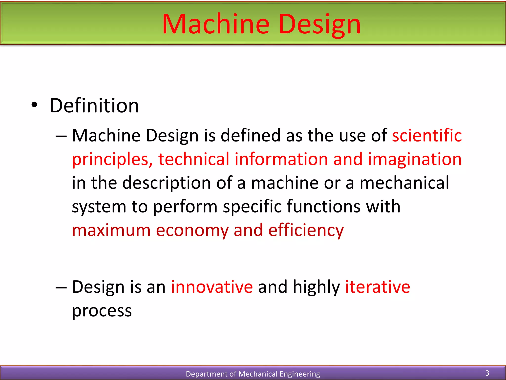
- It defines machine design and the iterative design process.
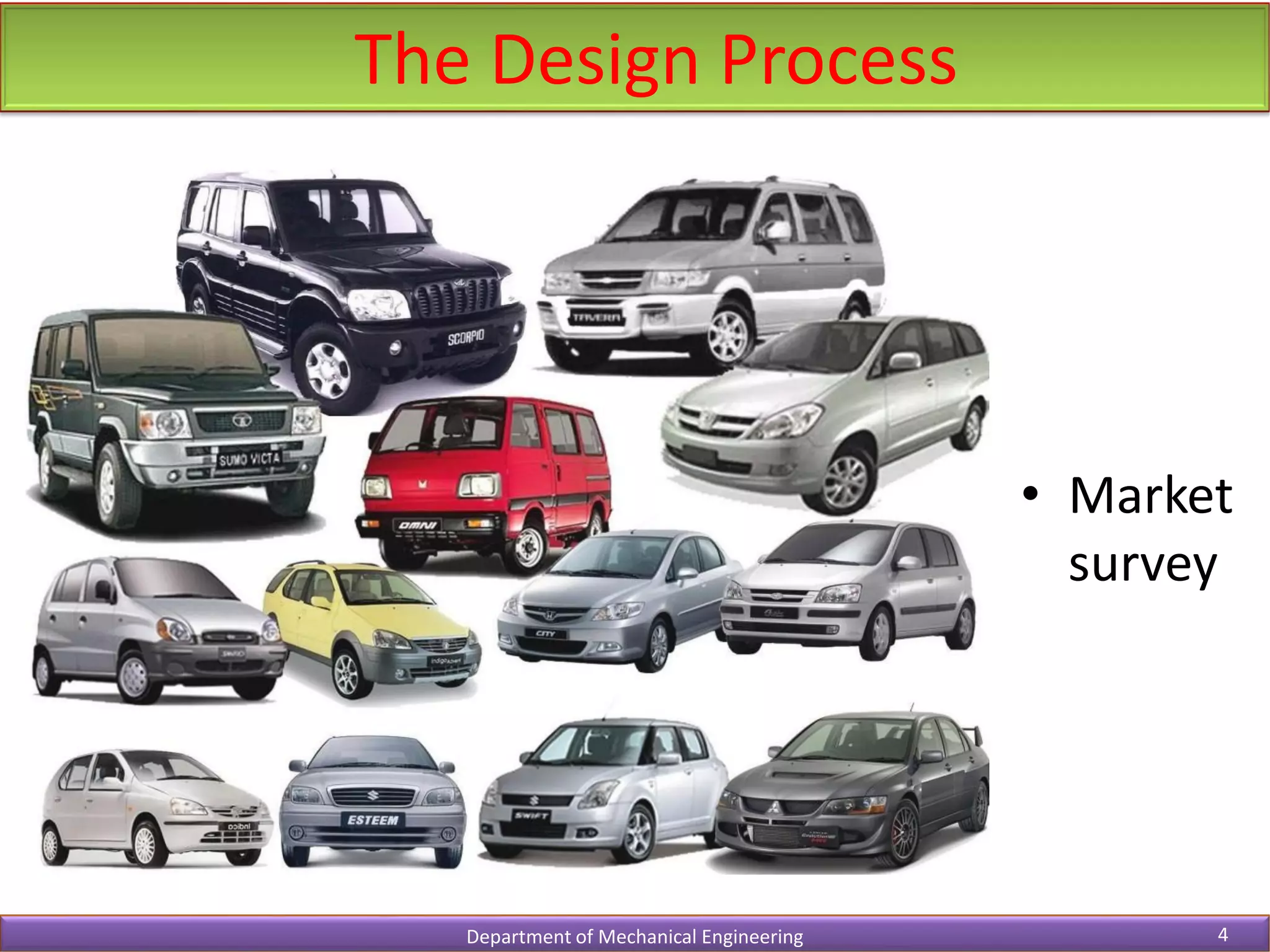
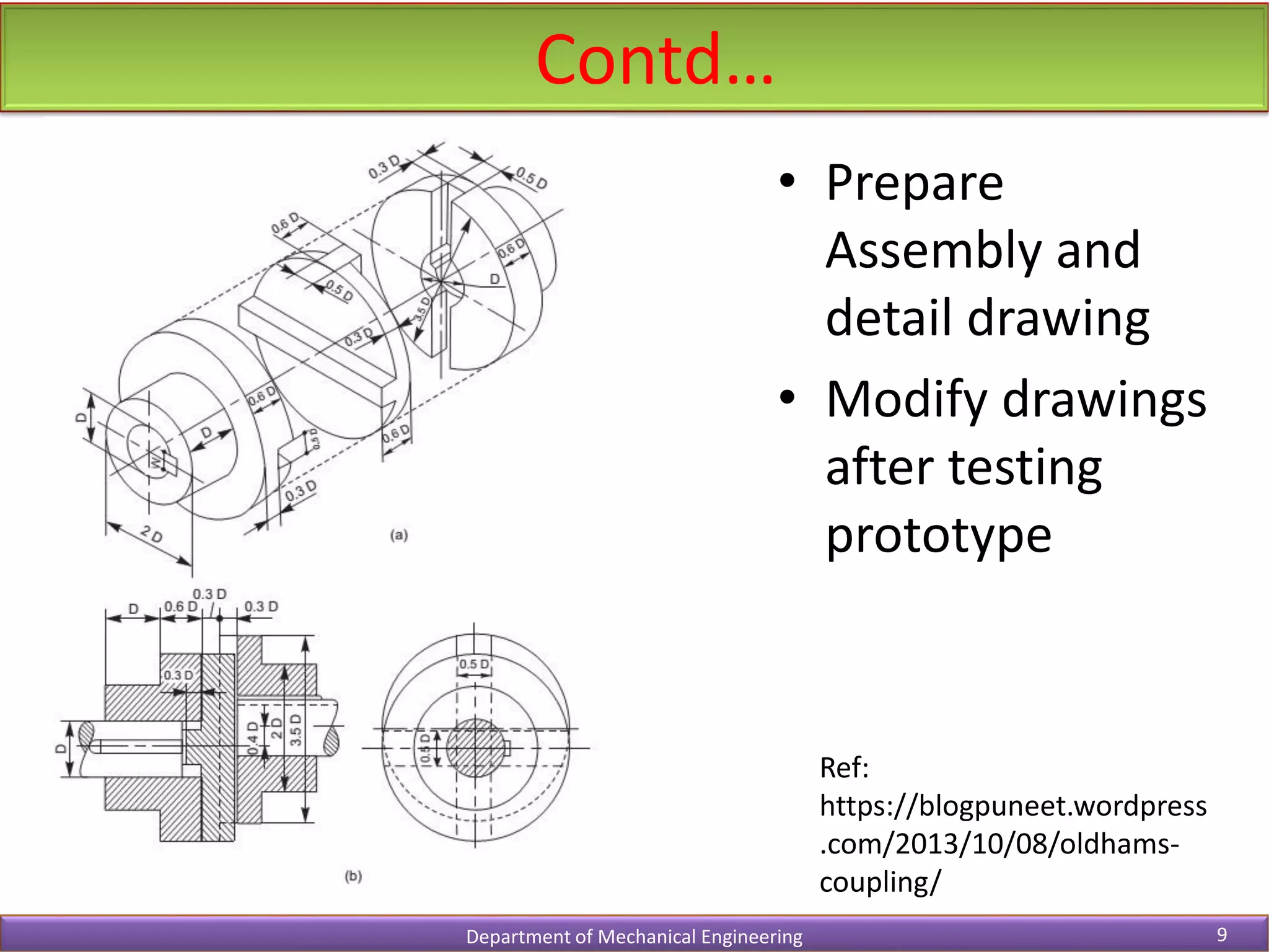
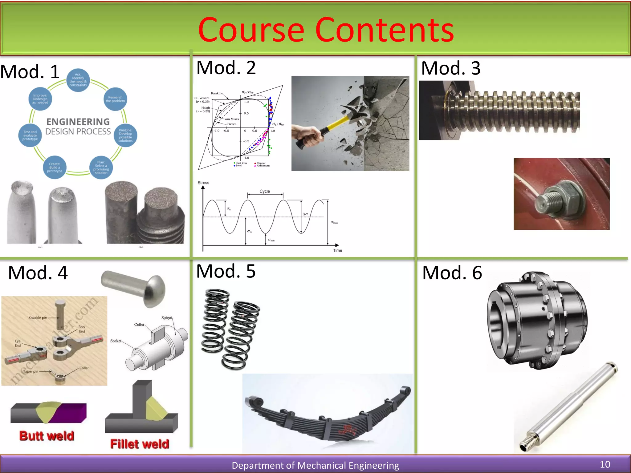
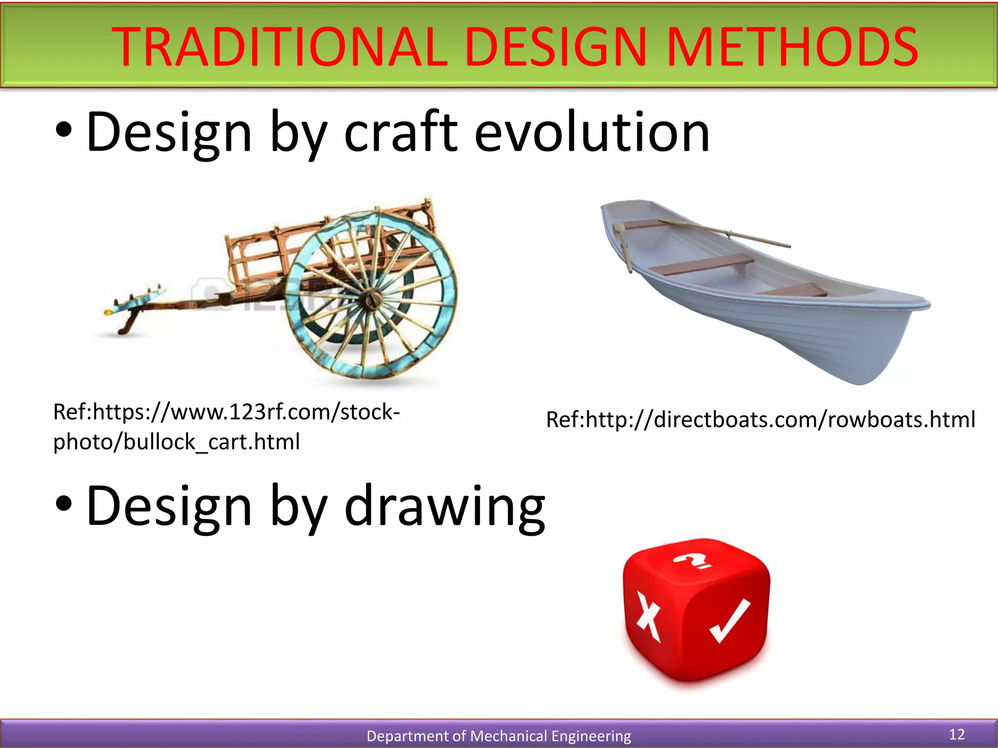
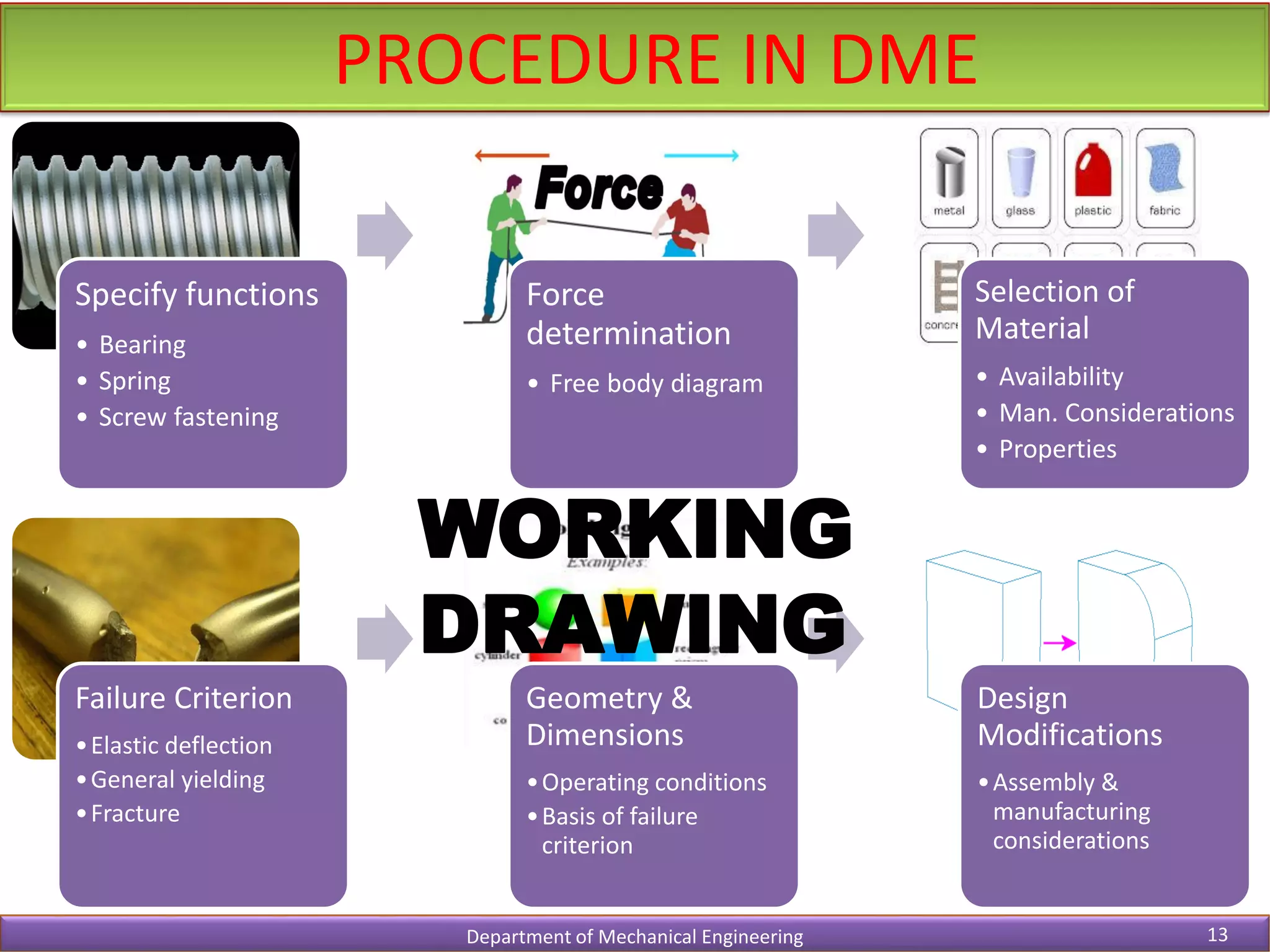
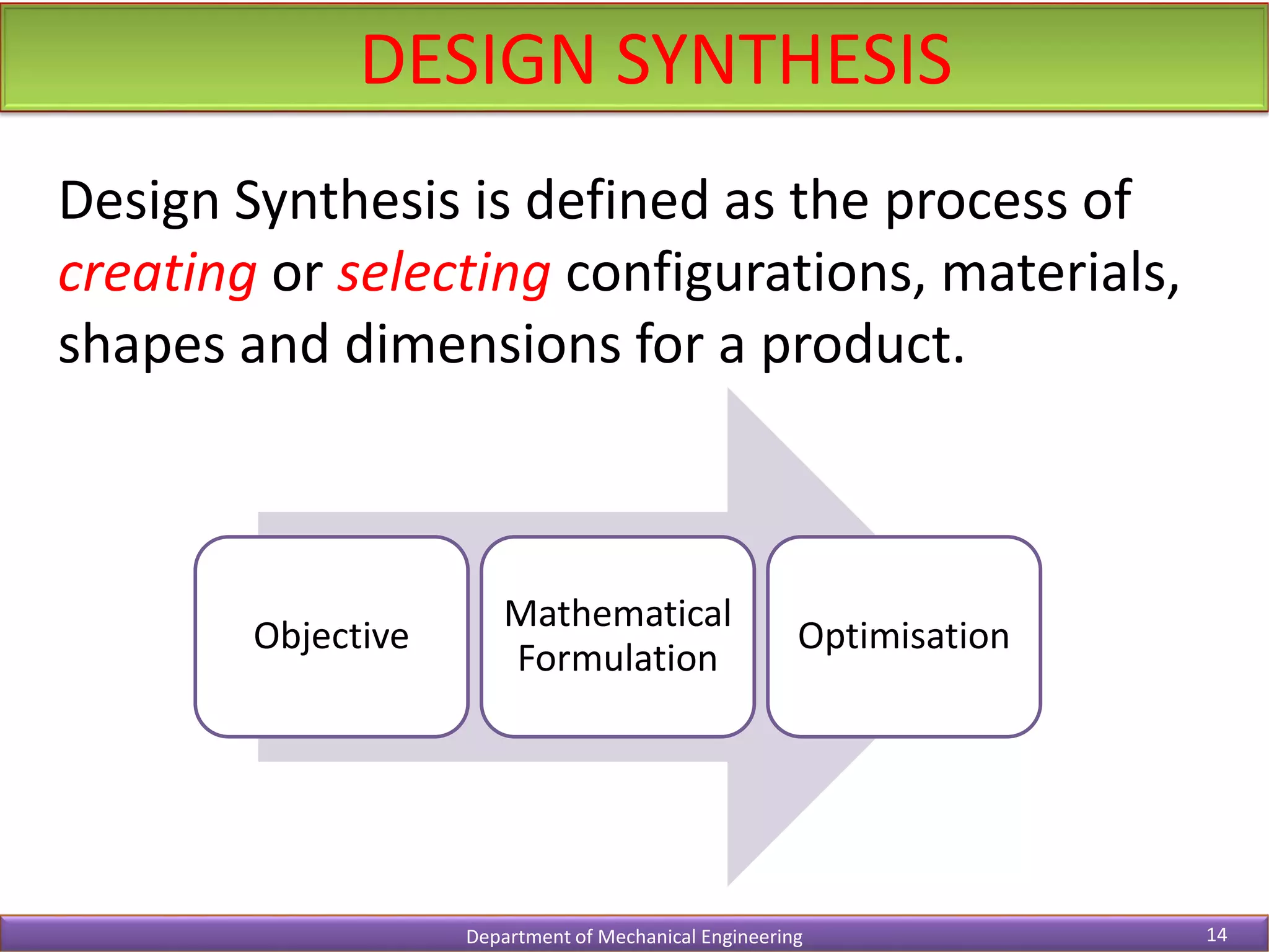
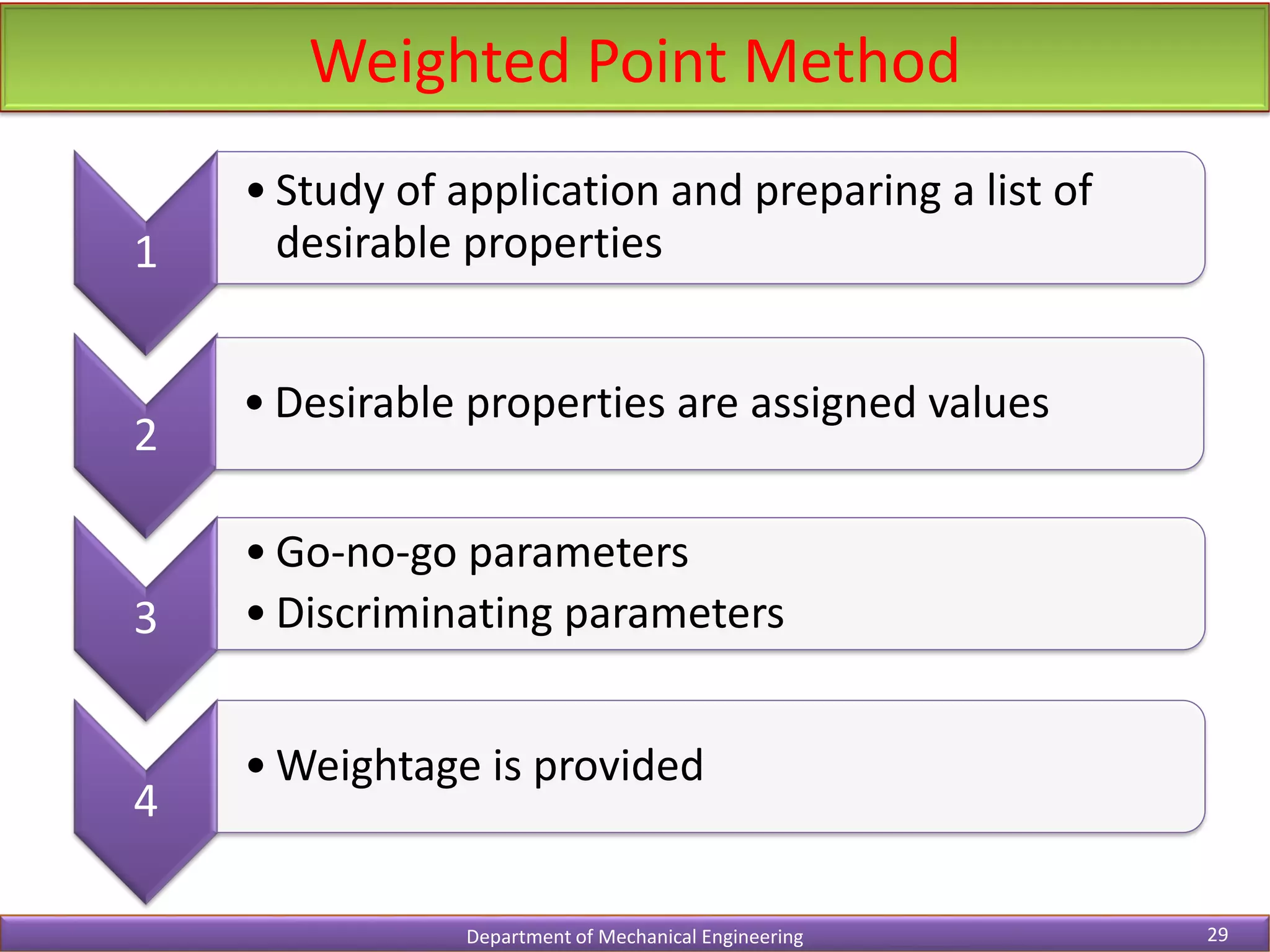
- It outlines the traditional and modern design processes including various stages like concept development, analysis, and testing.
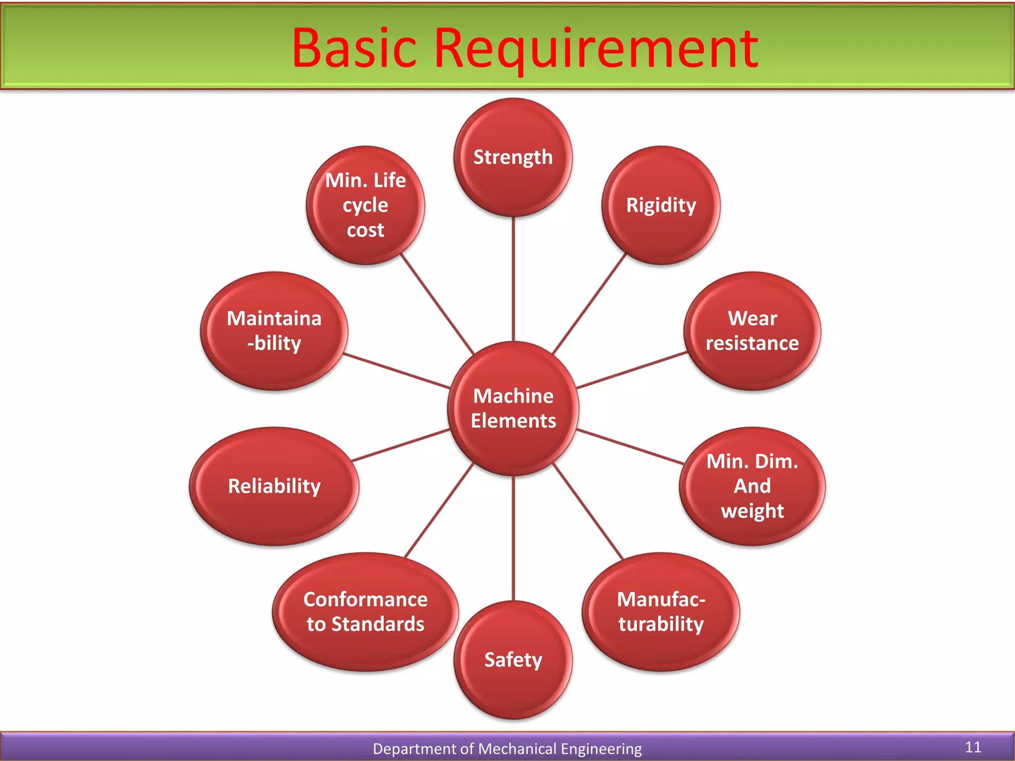
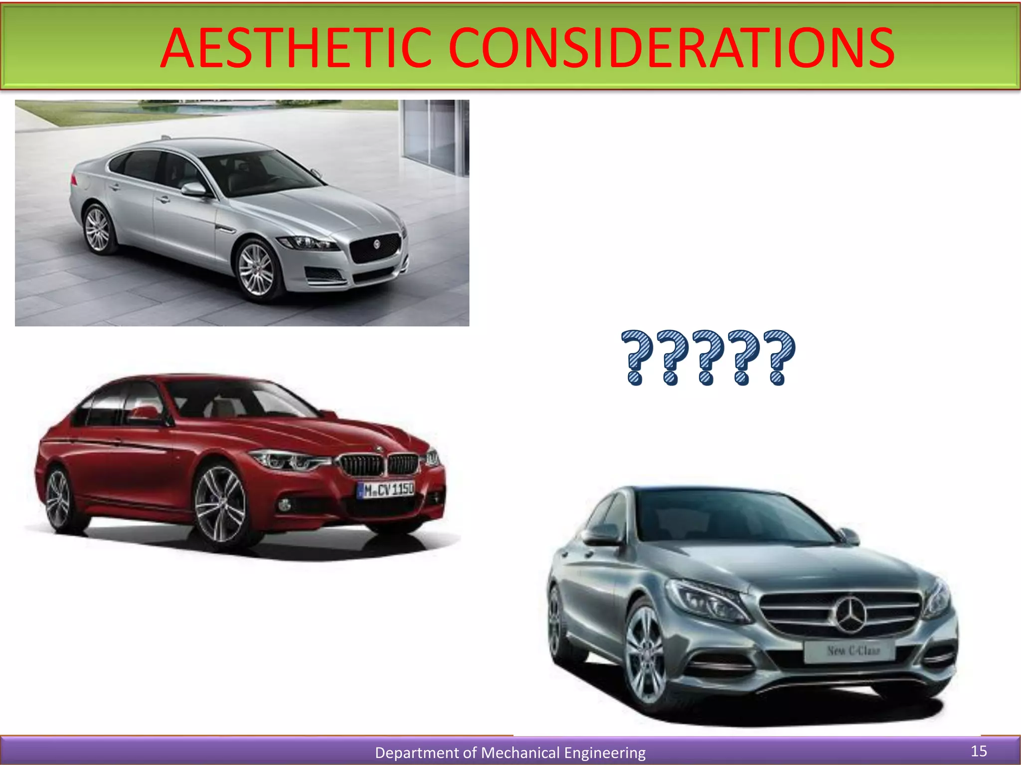
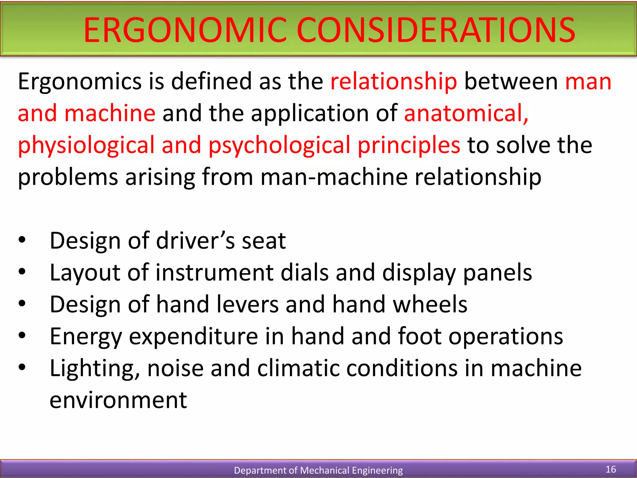
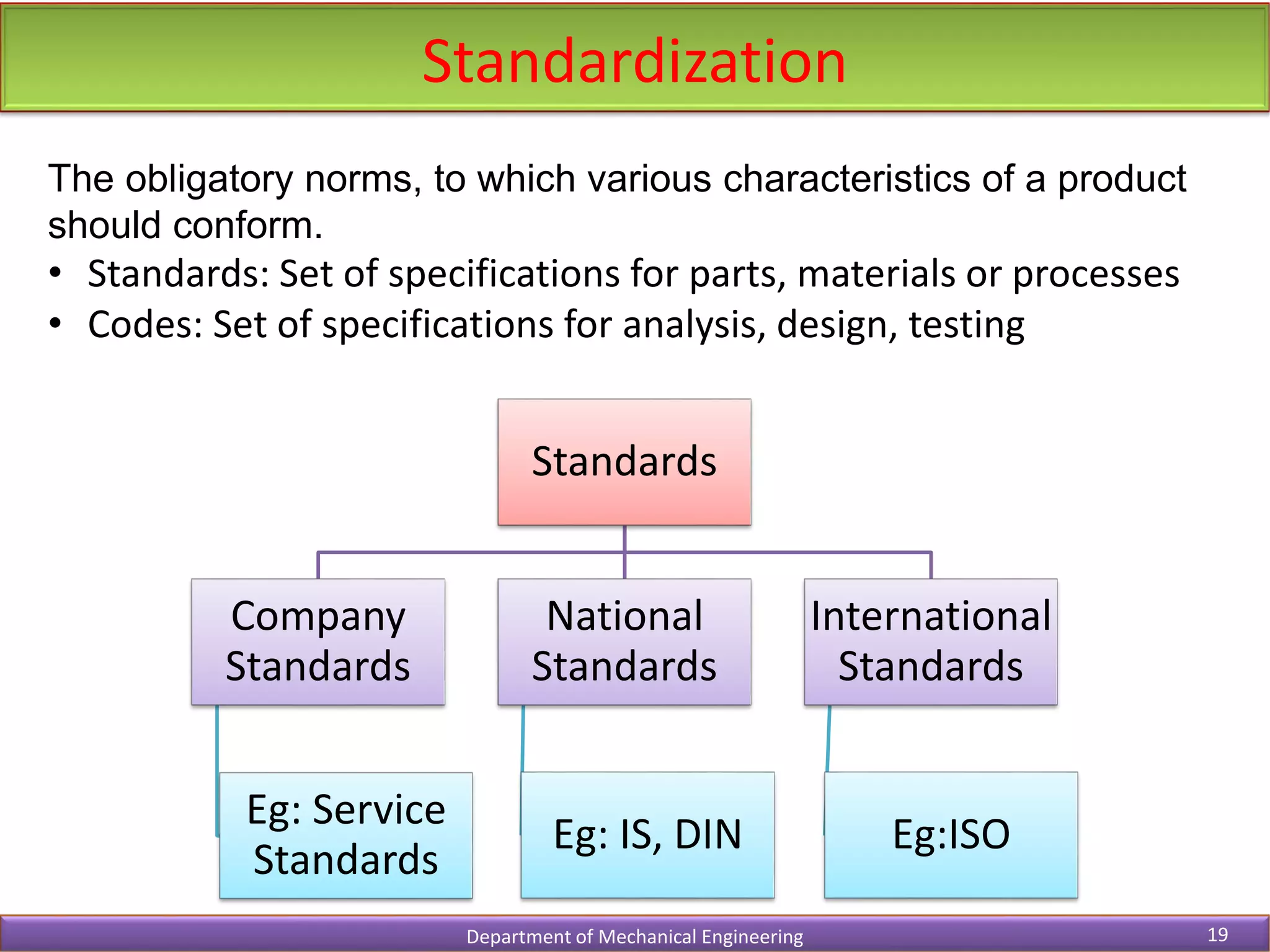
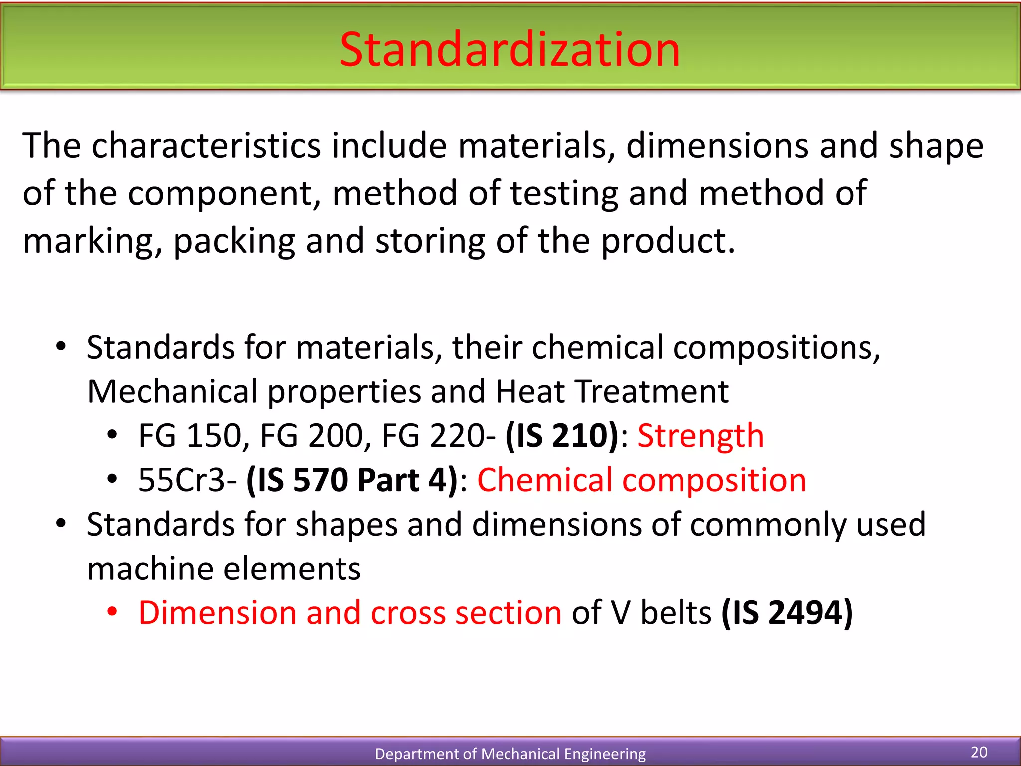
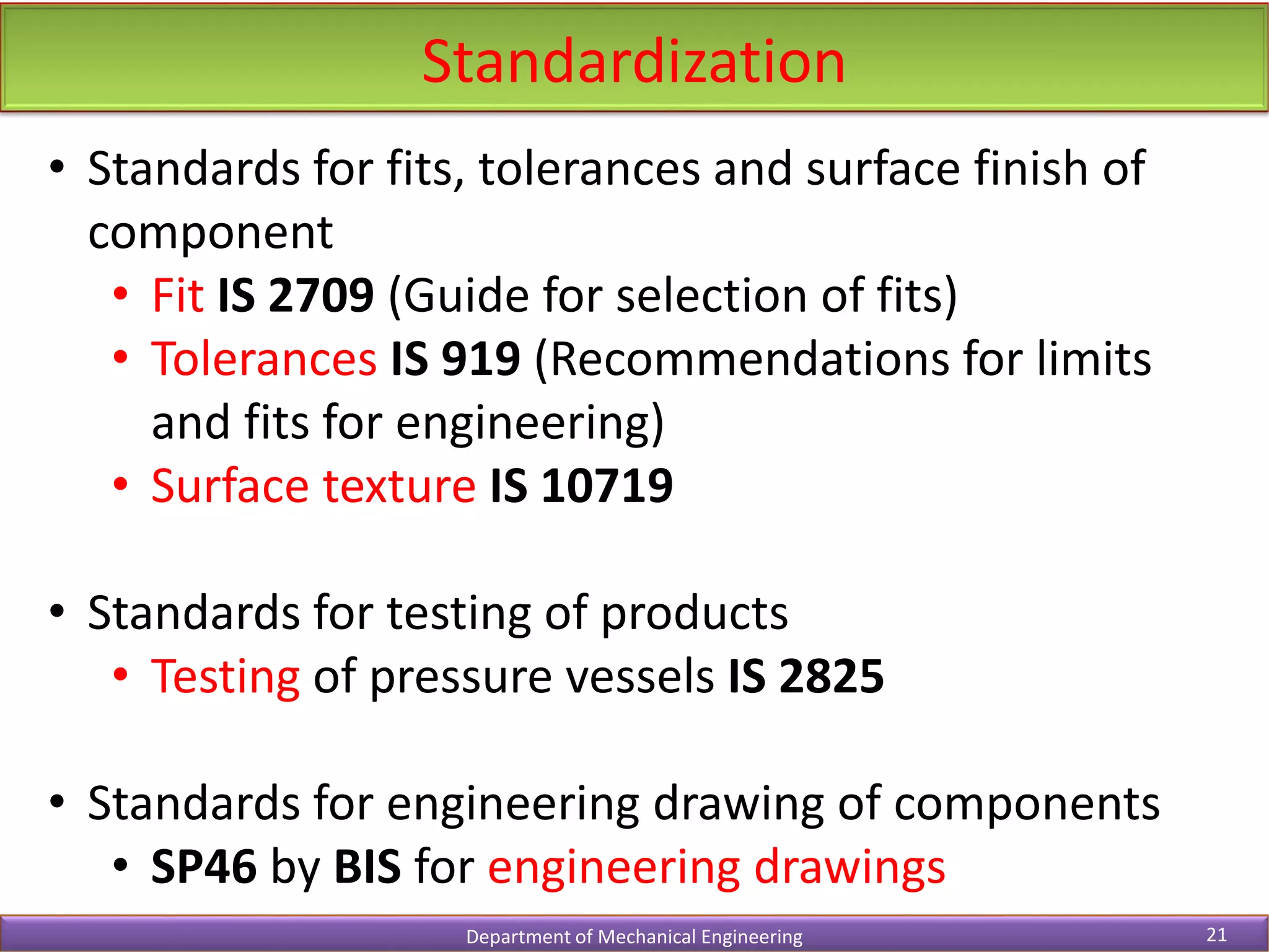
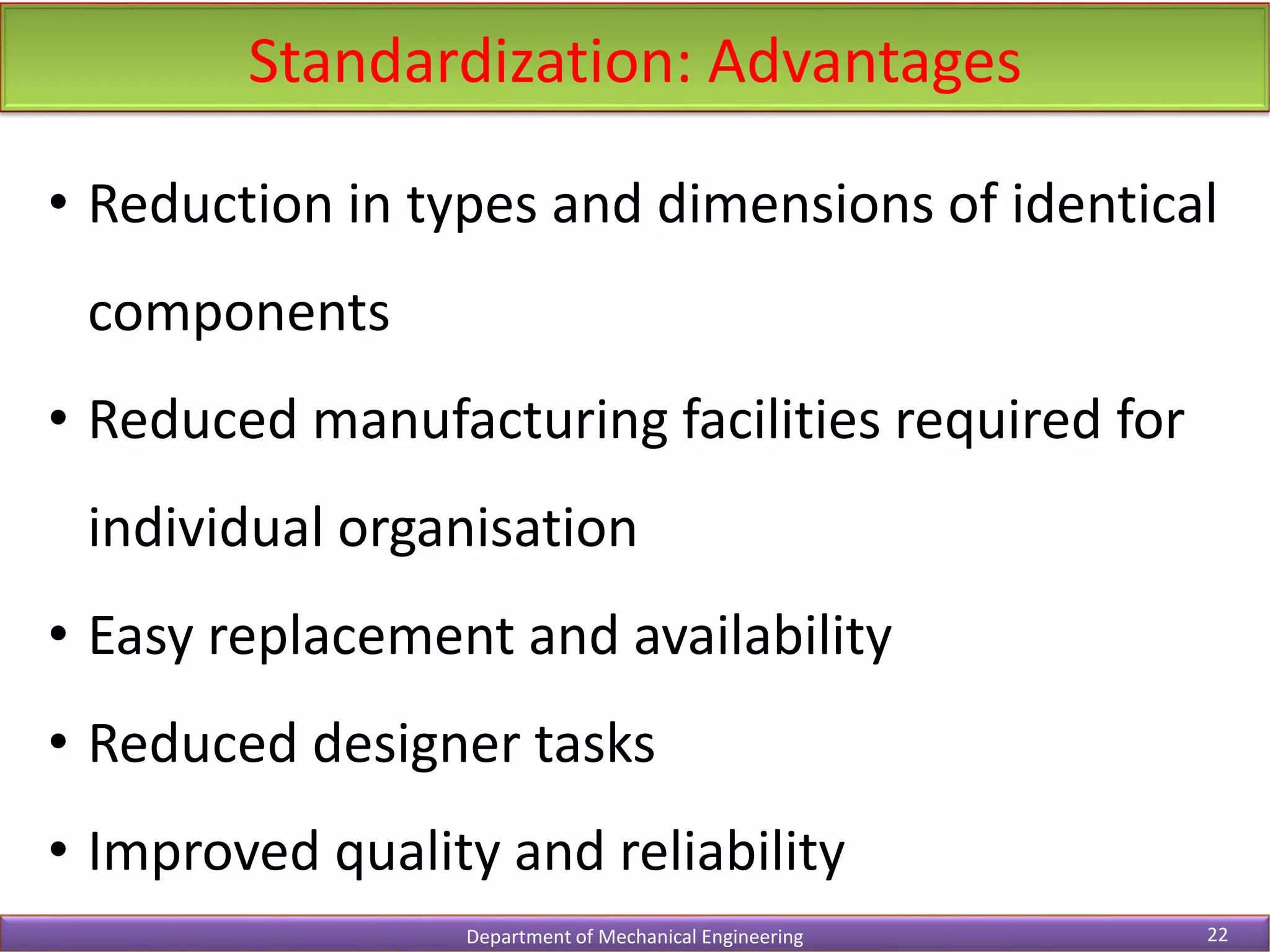
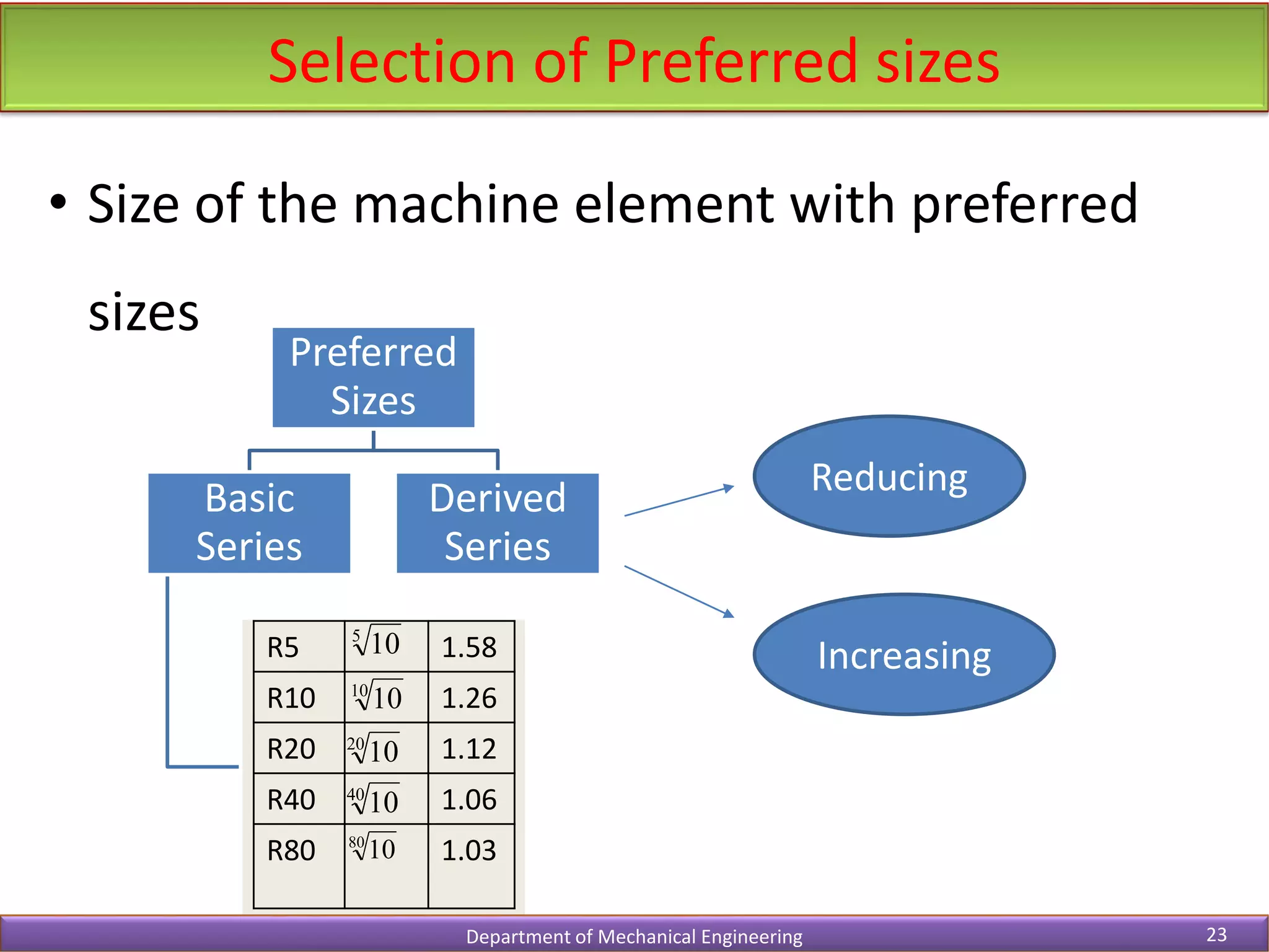
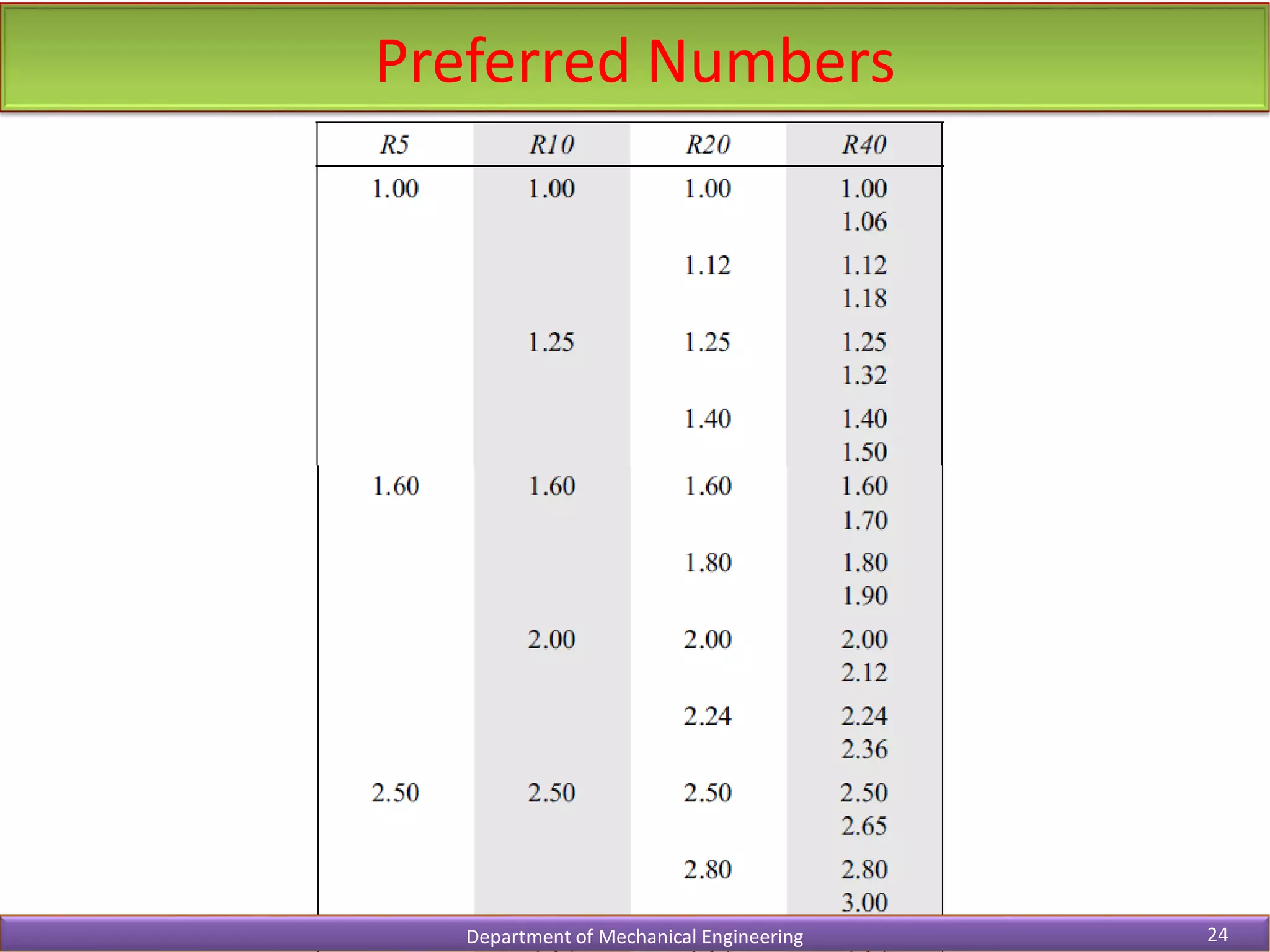
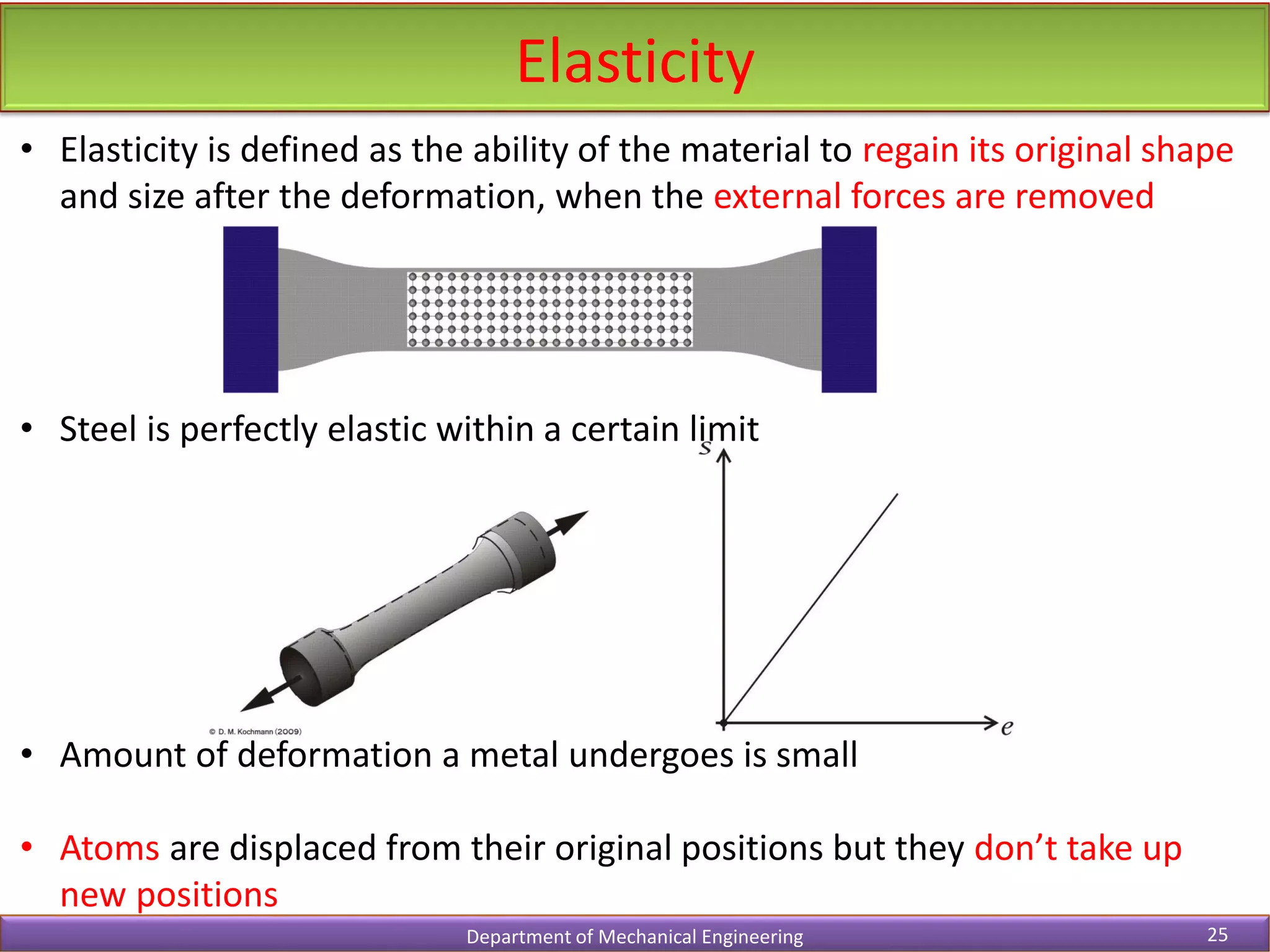
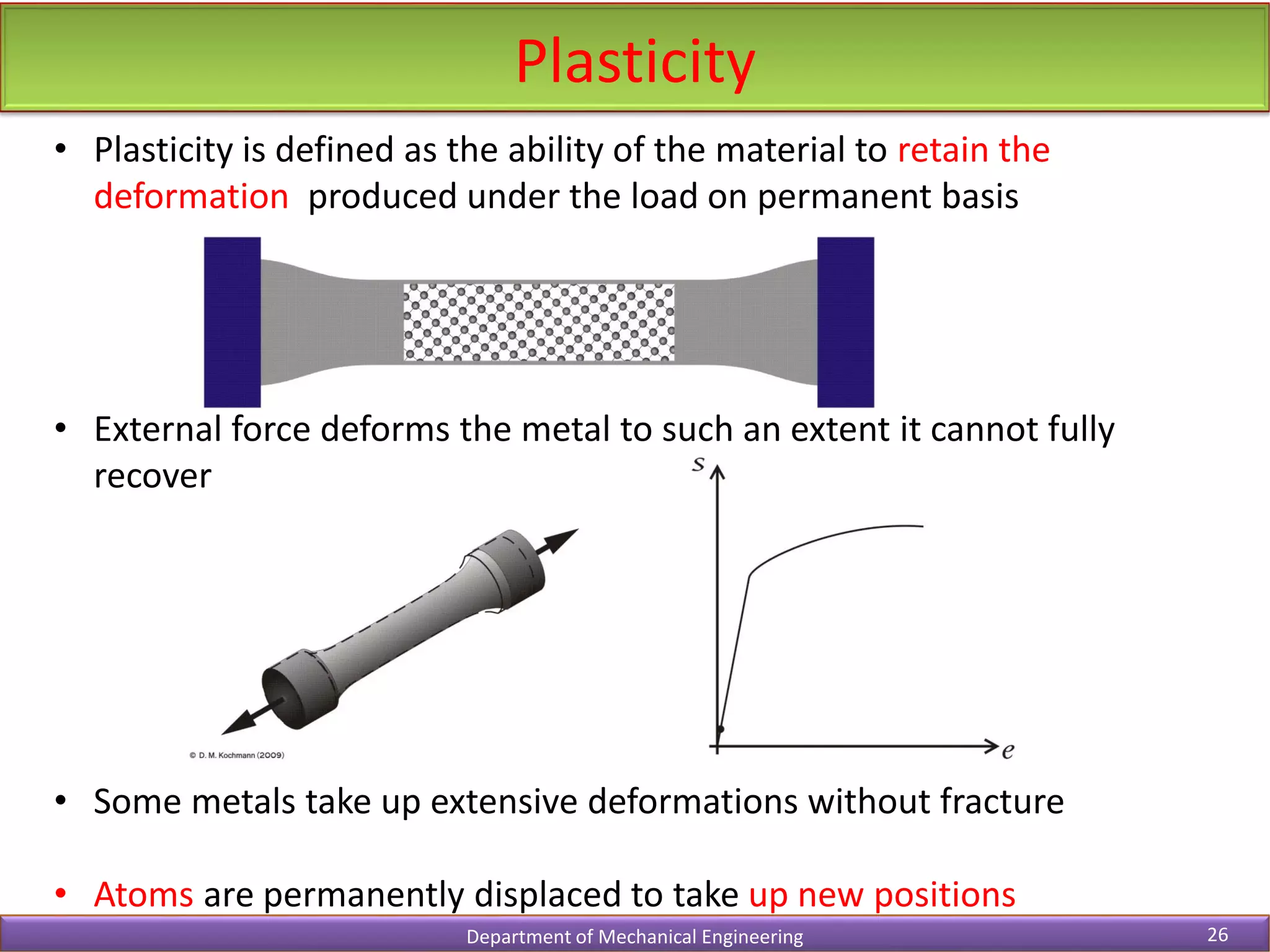
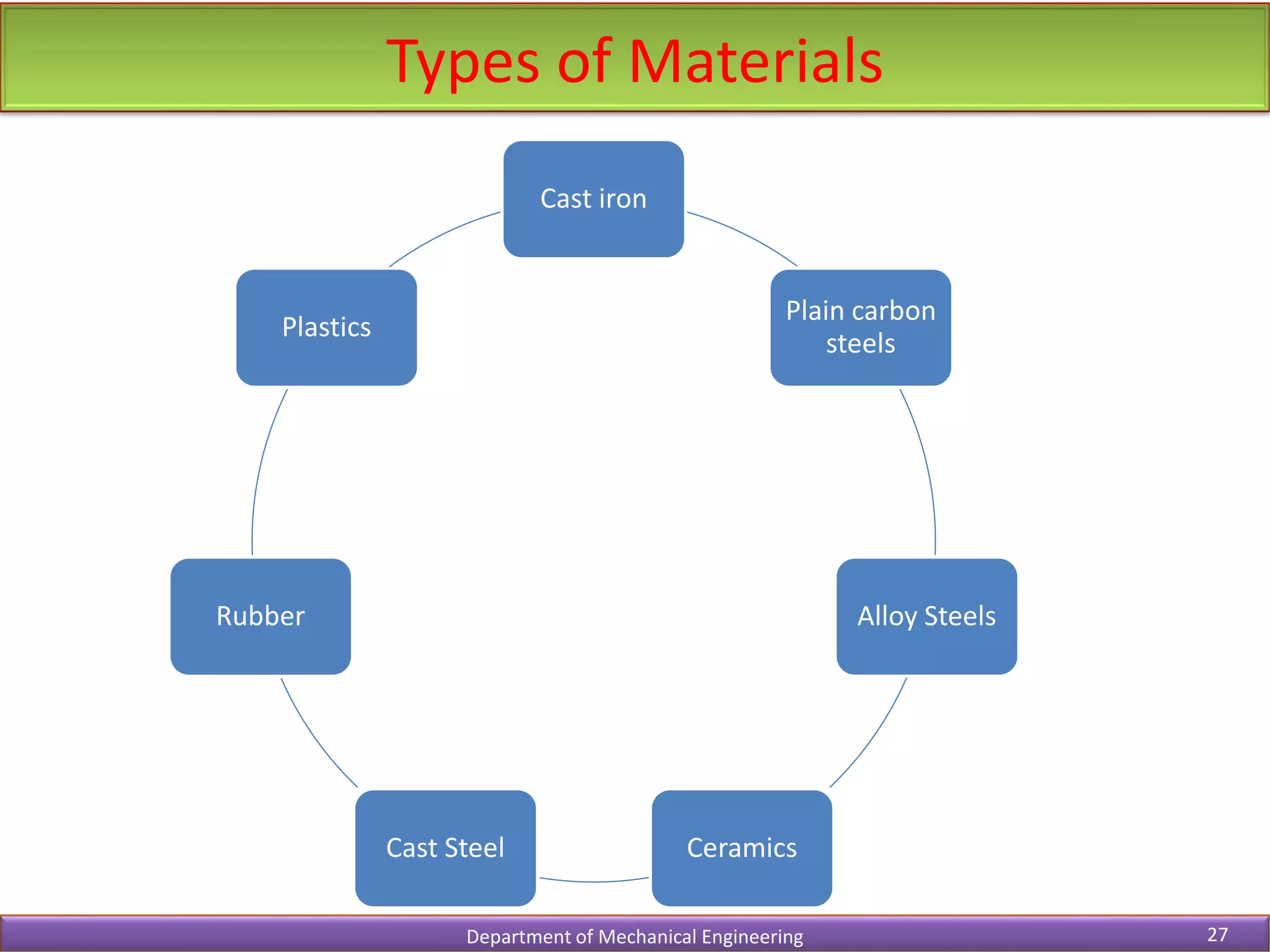
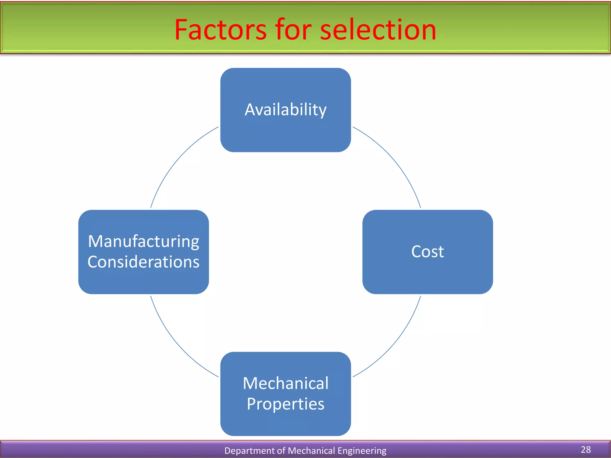
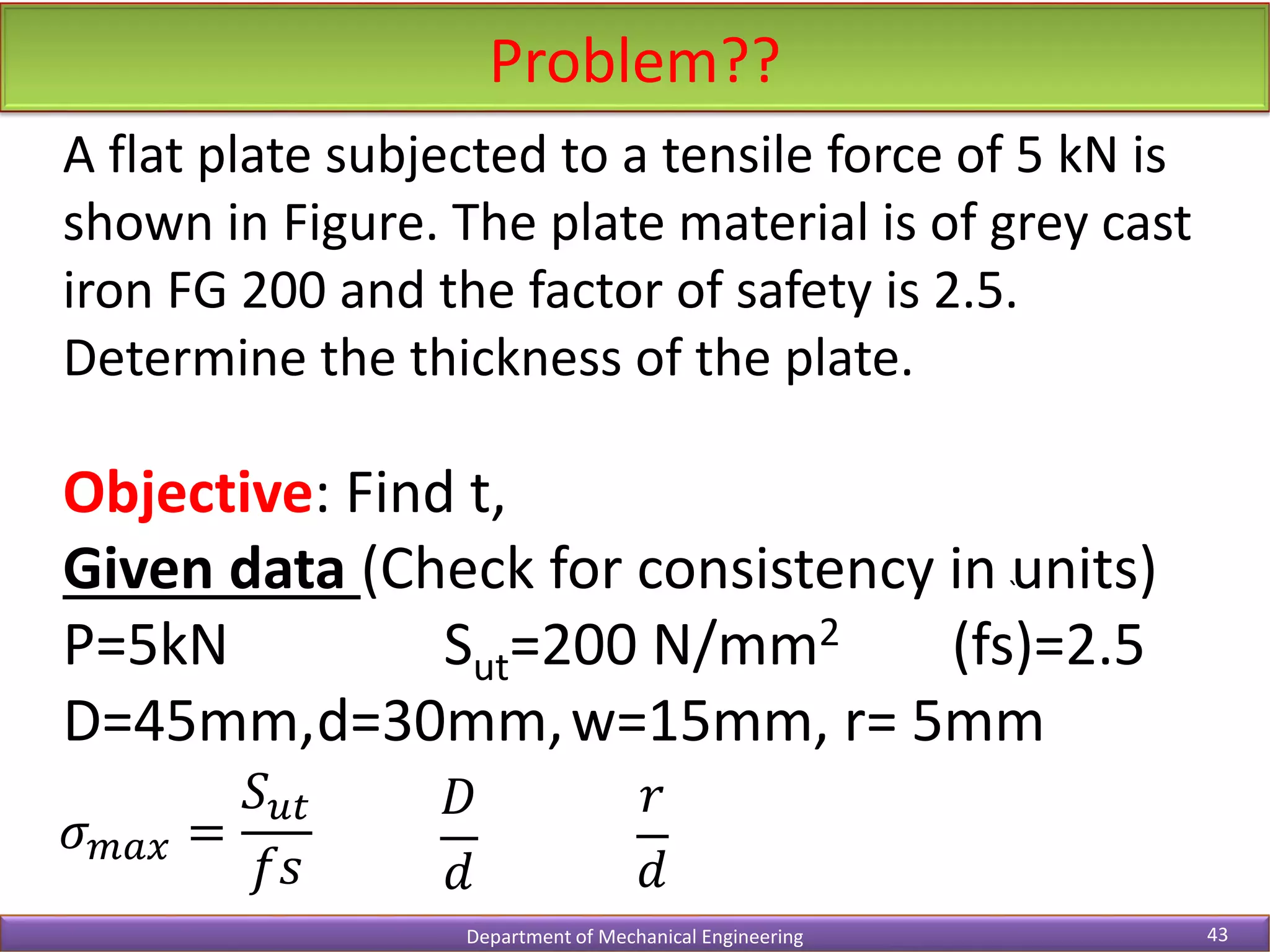
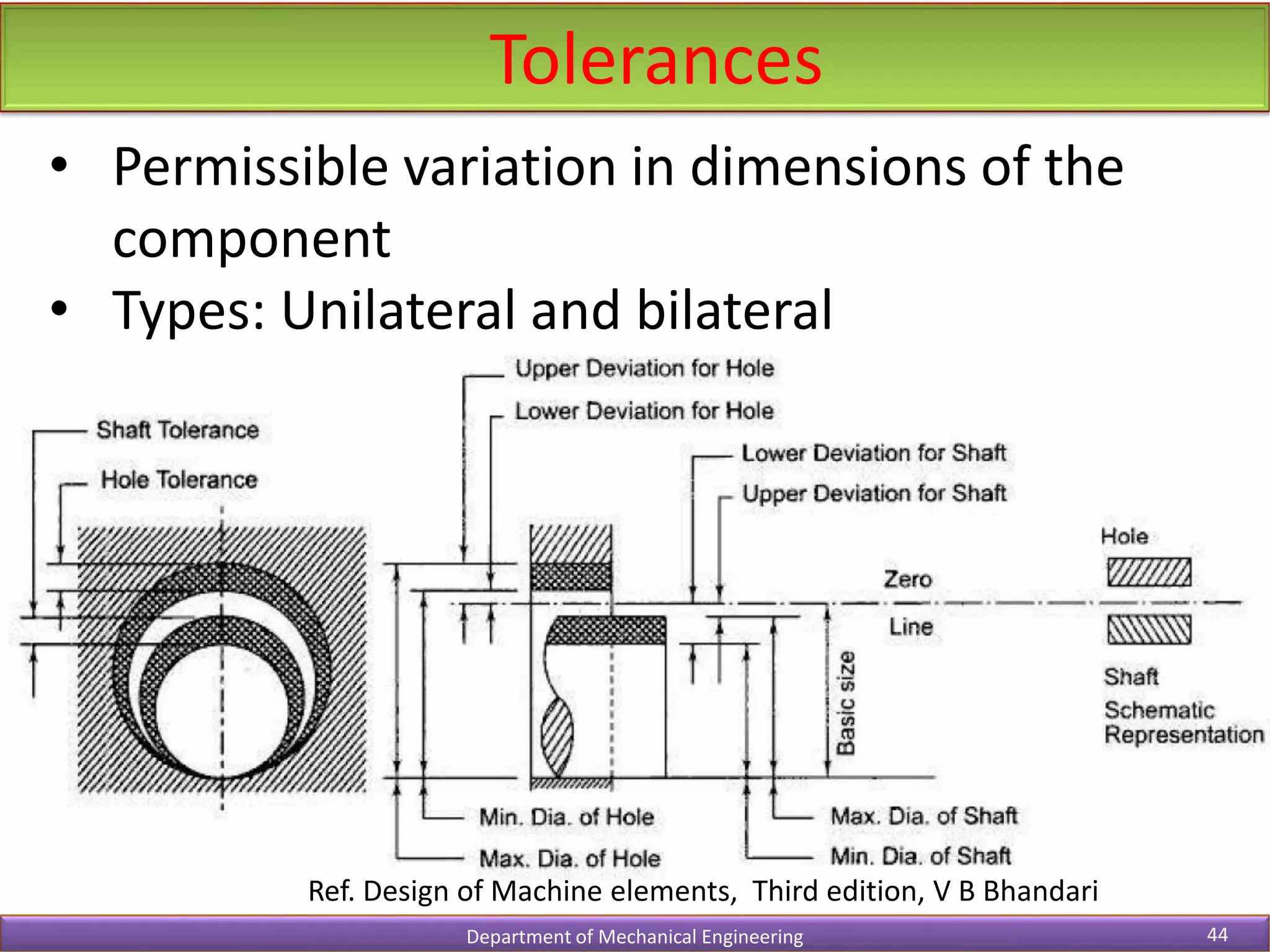
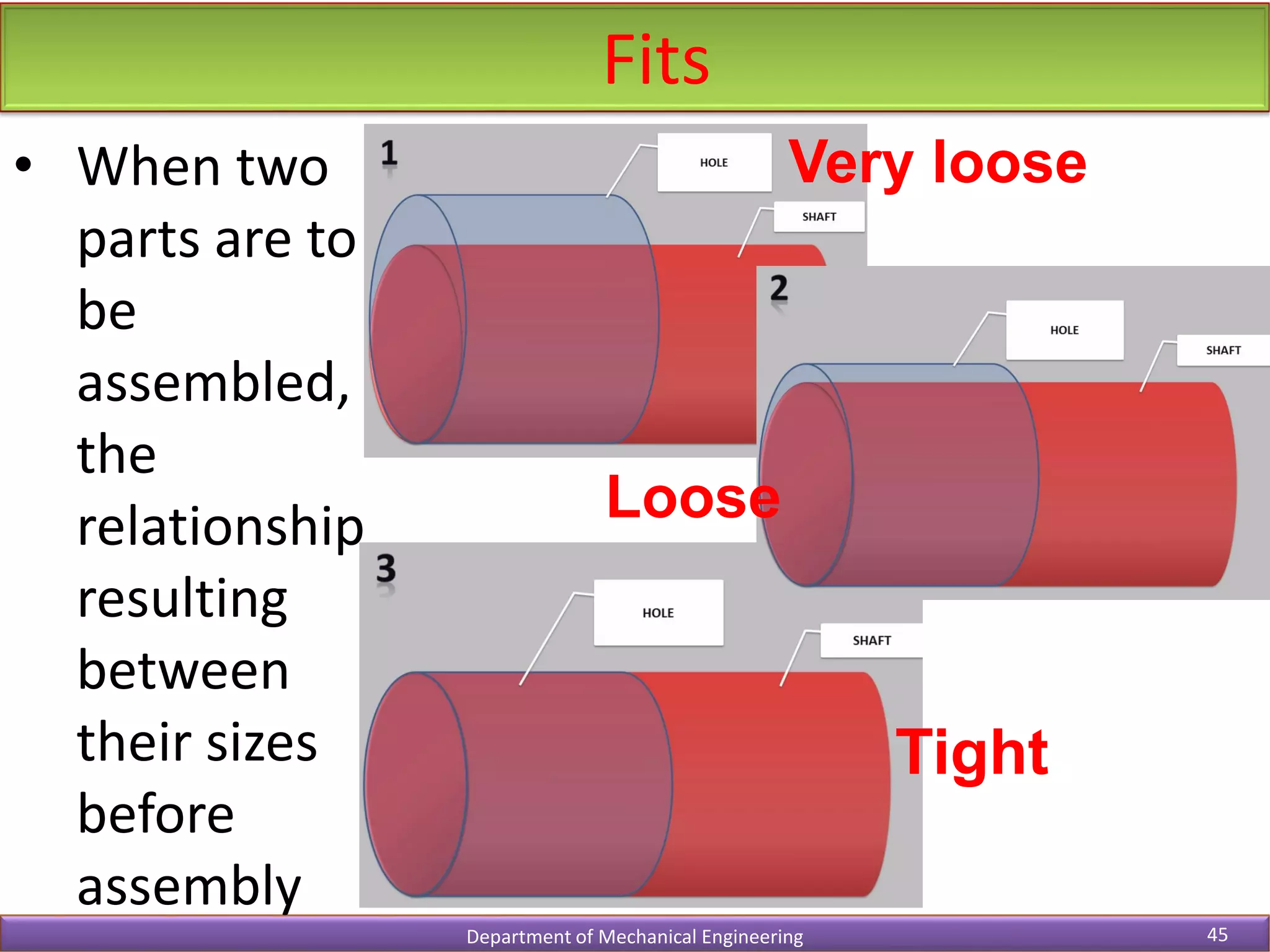
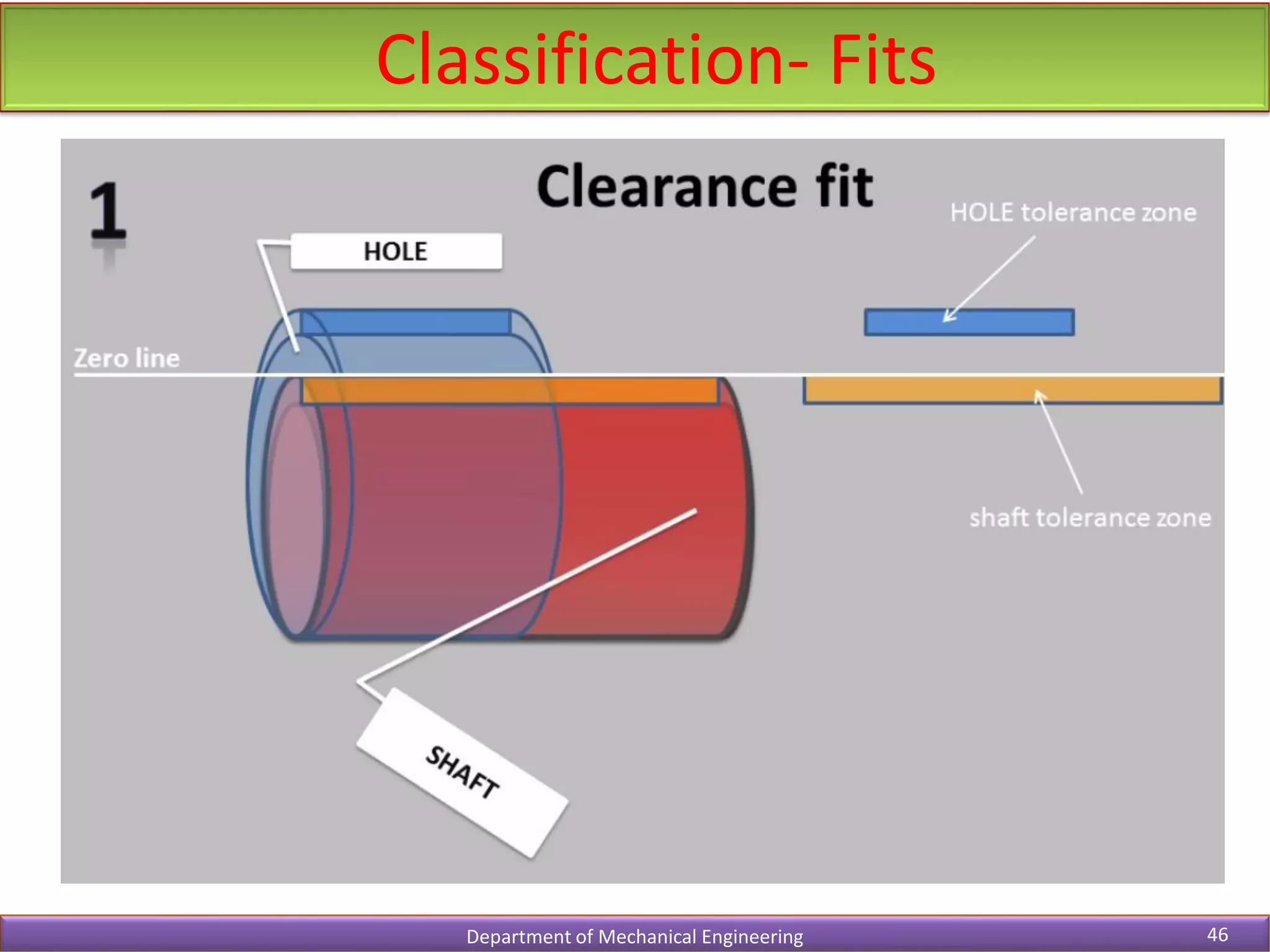
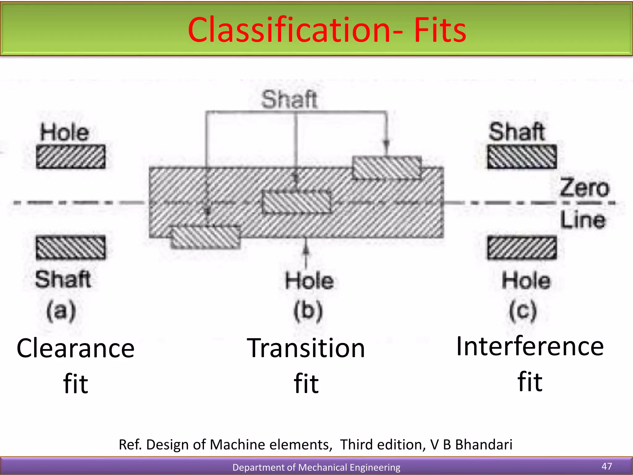
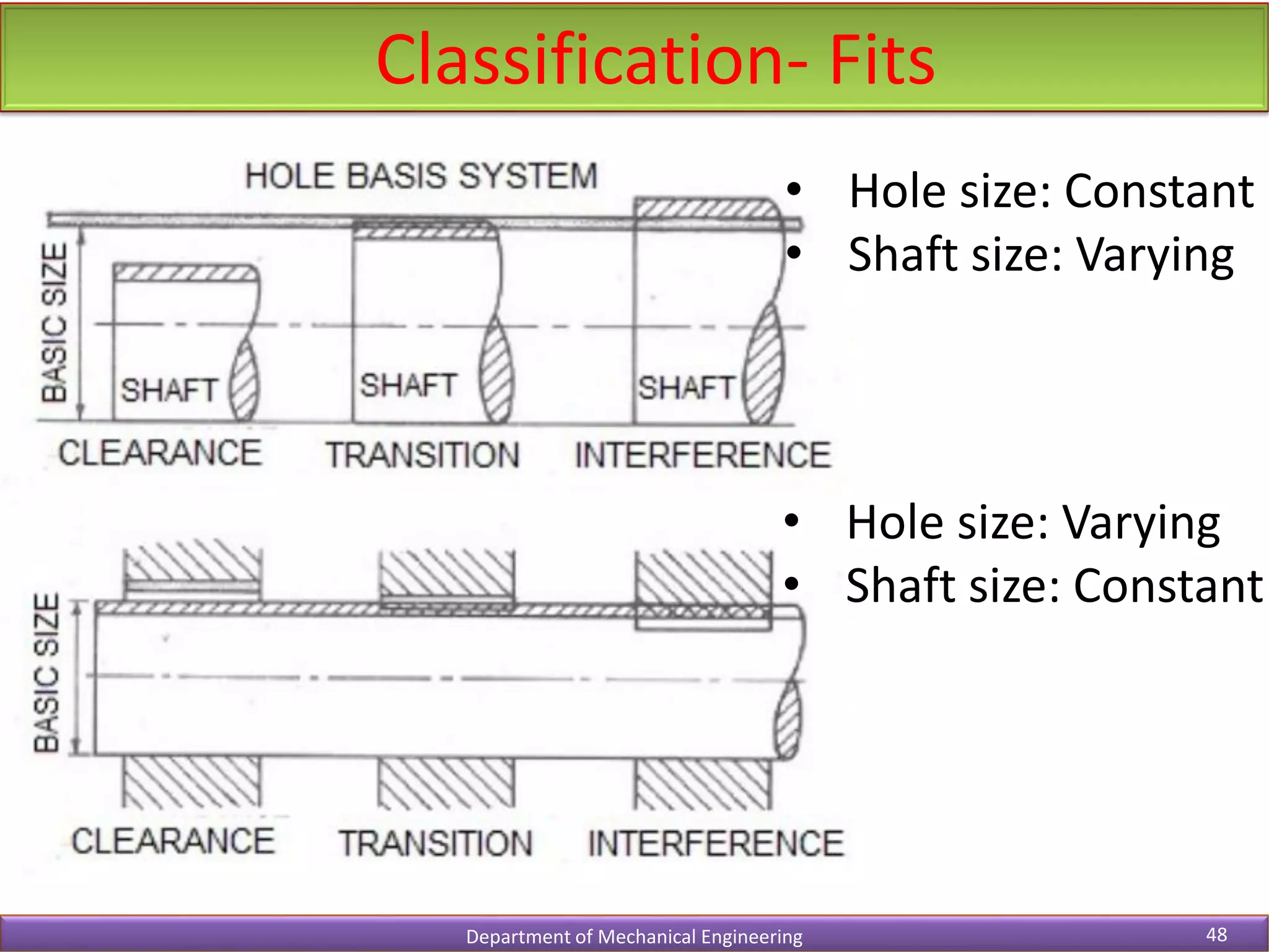
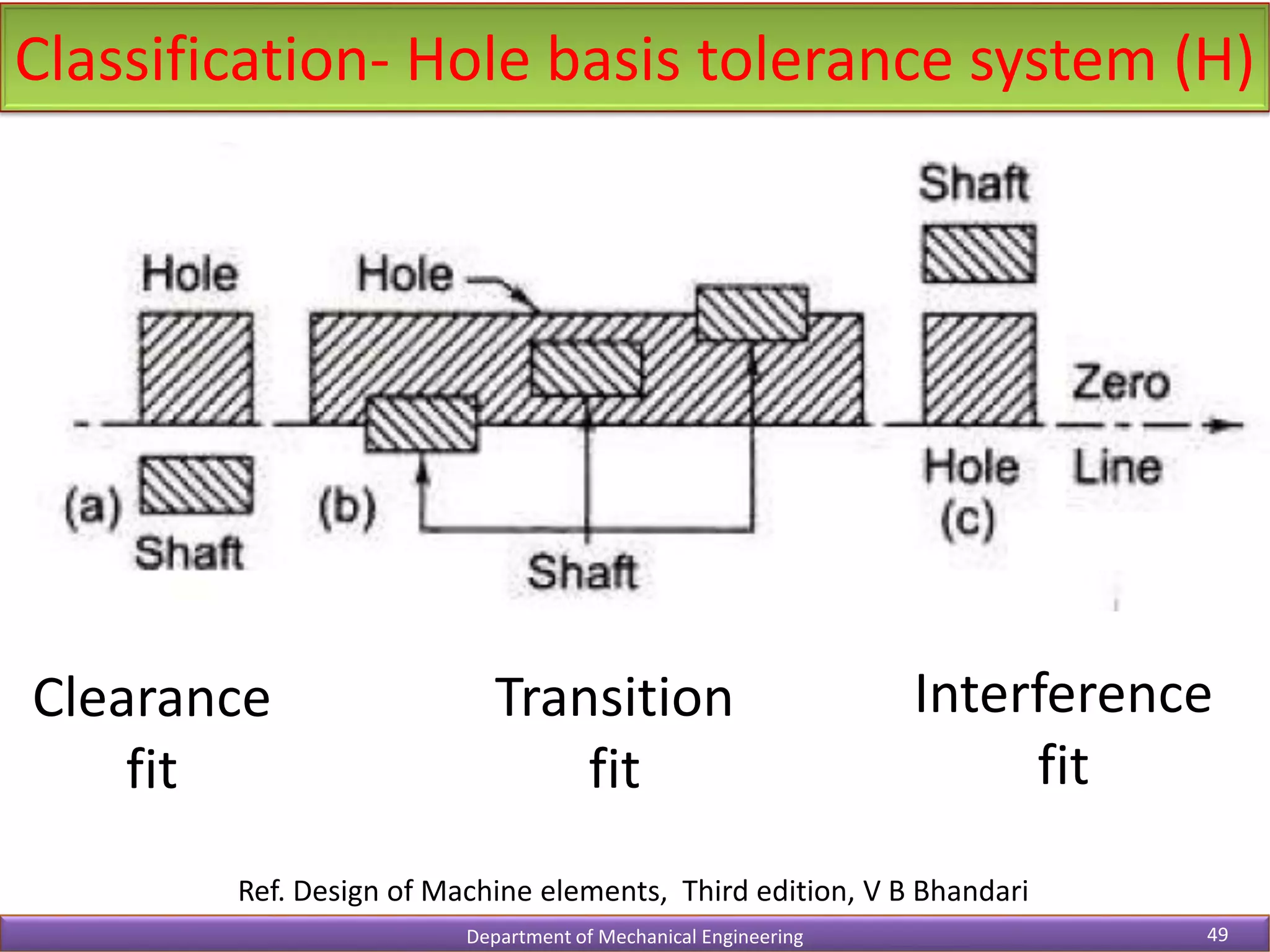
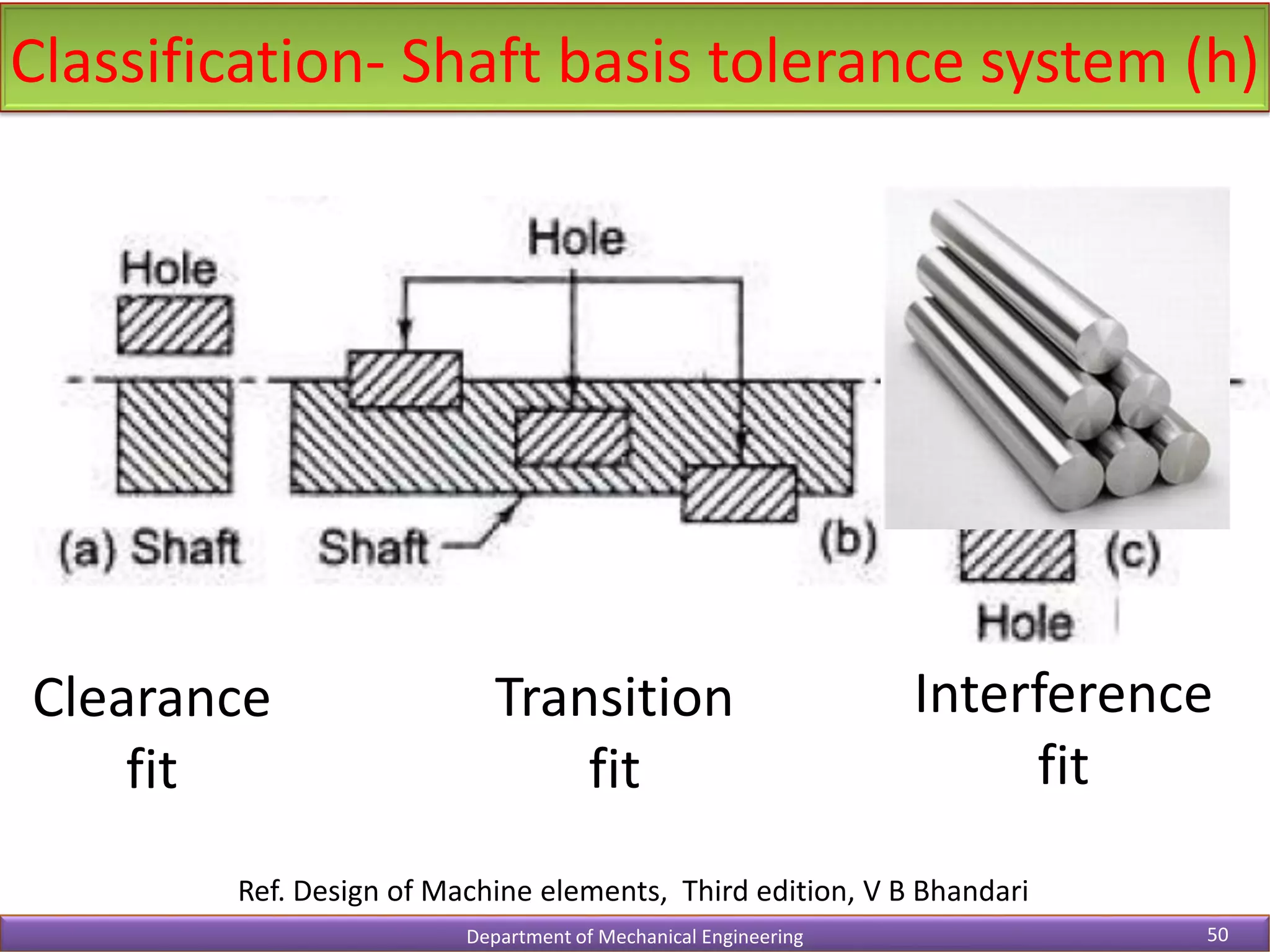
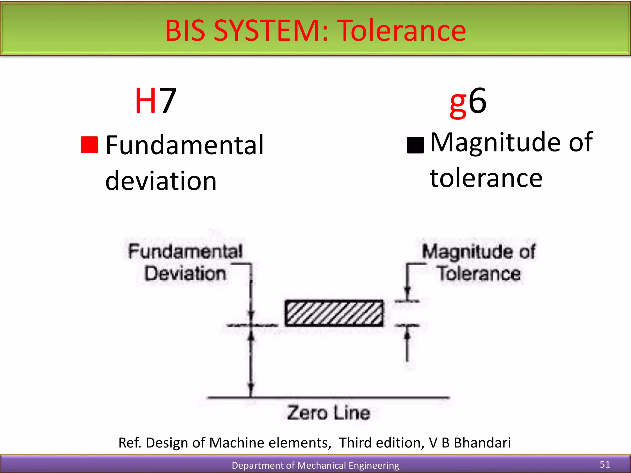
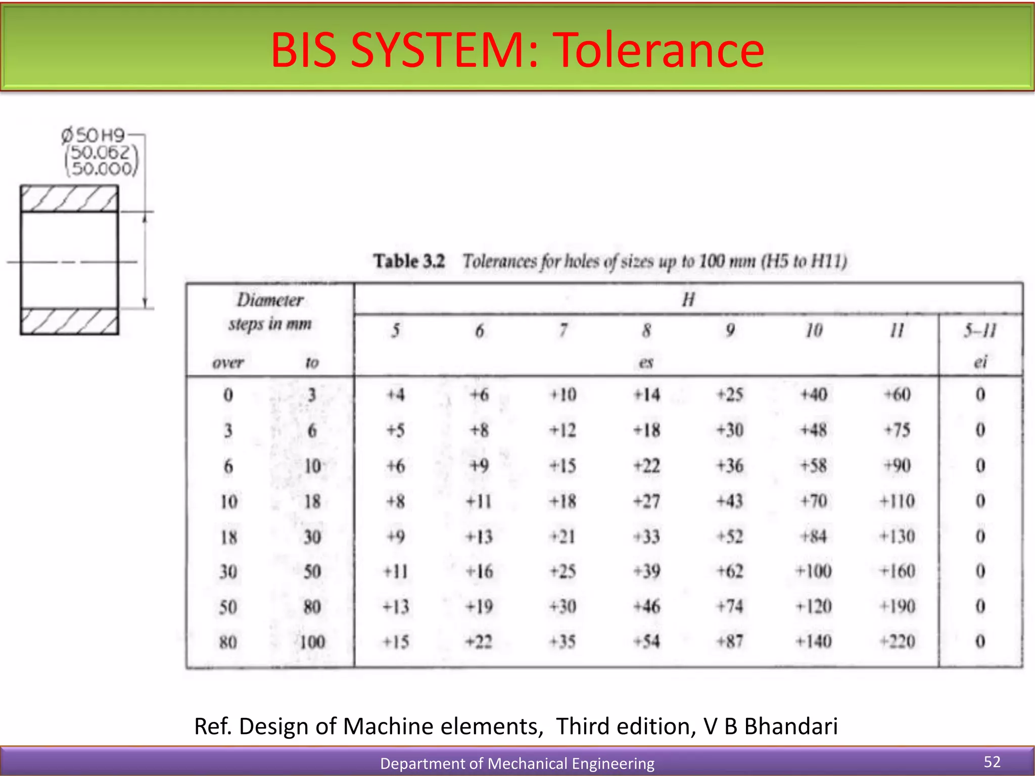
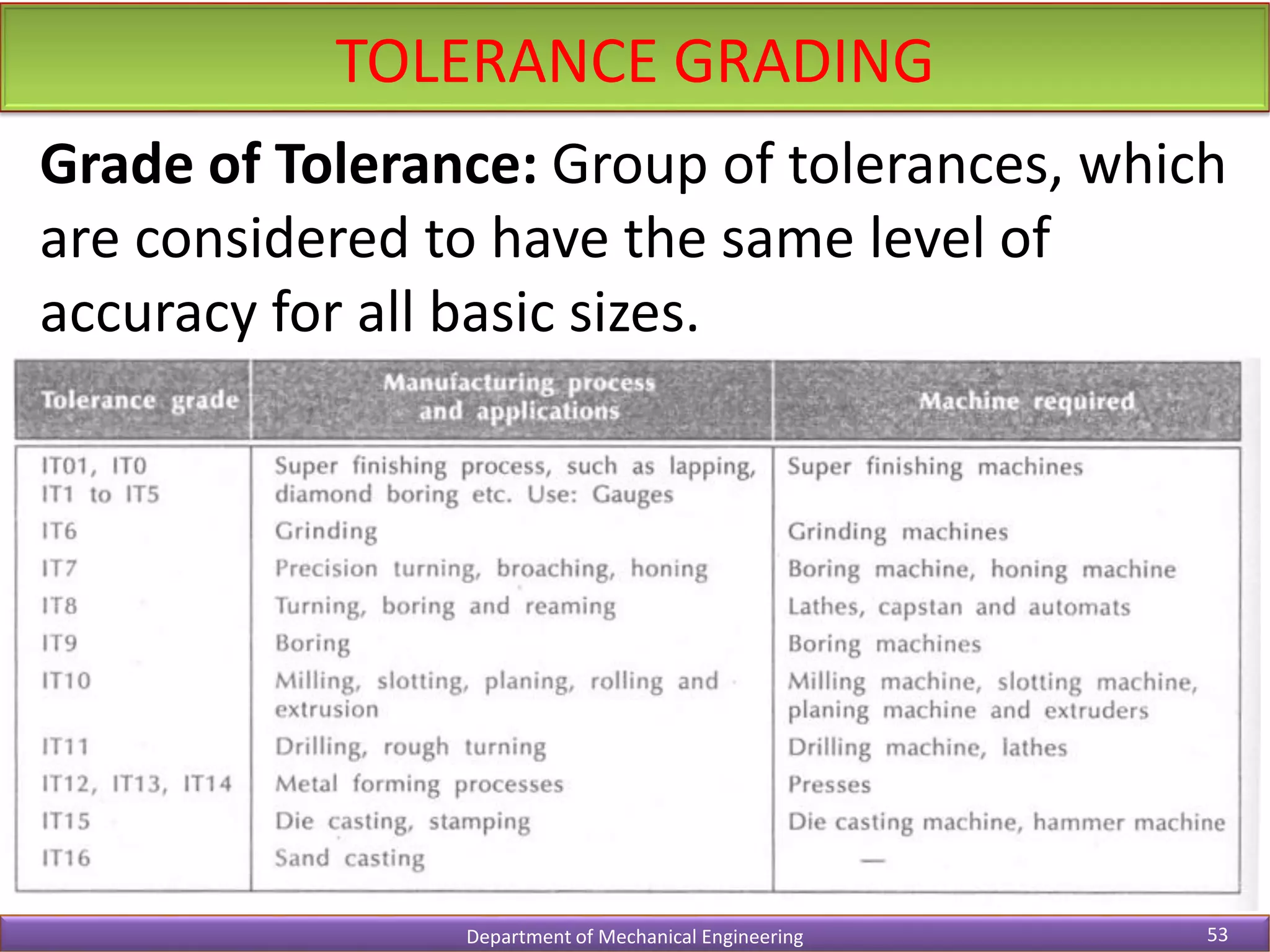
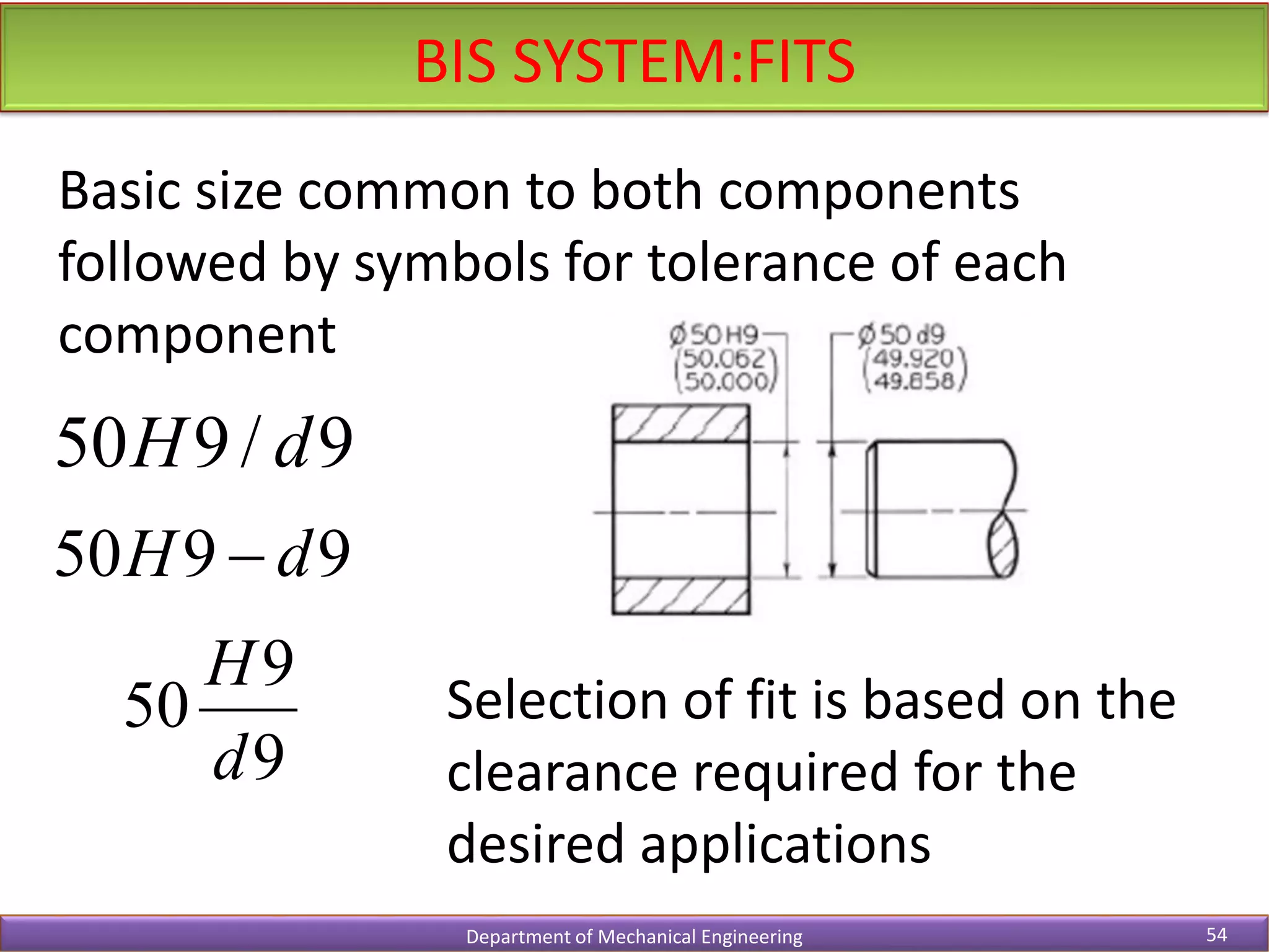
- It covers topics like design considerations, standardization, selection of materials, stress analysis, fits and tolerances.
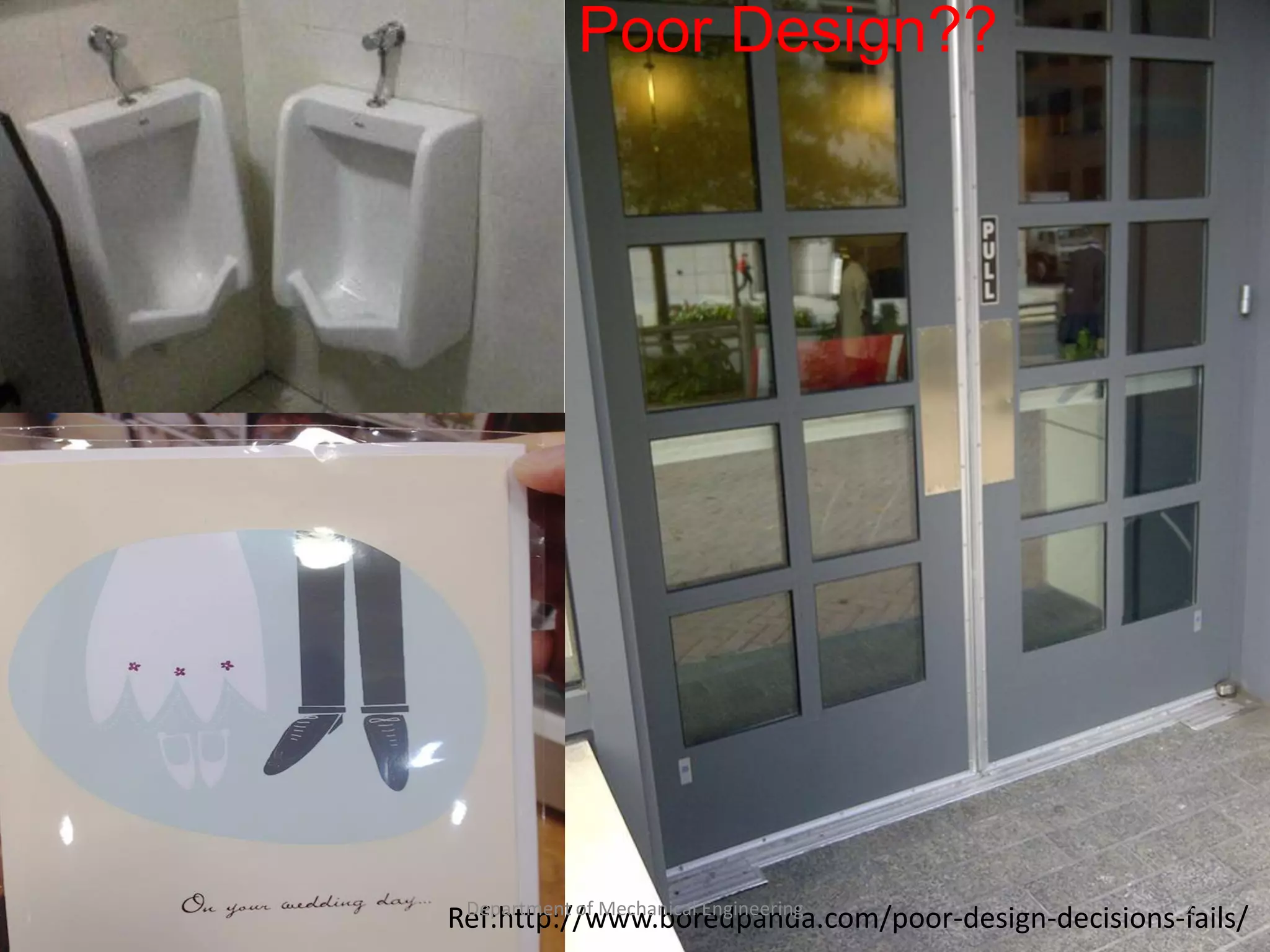
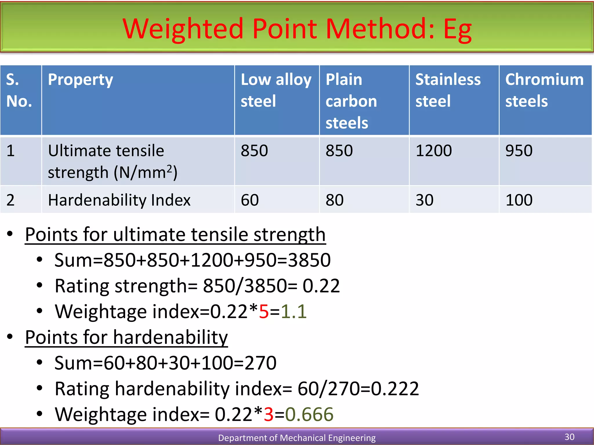
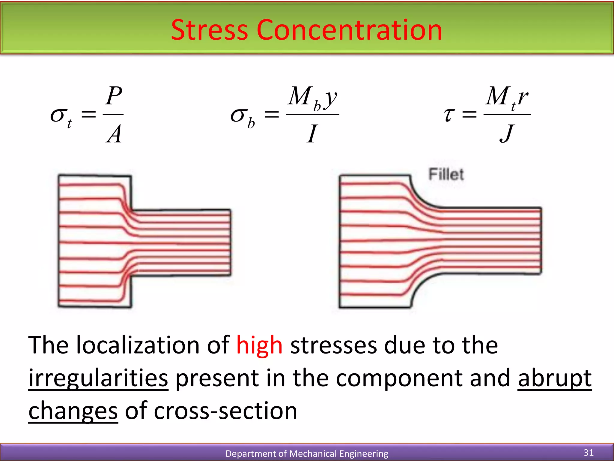
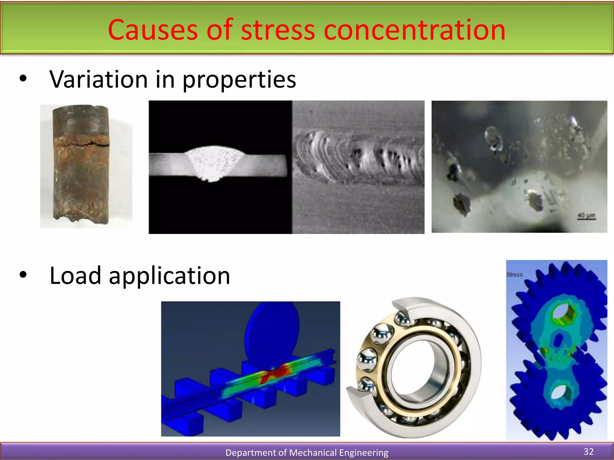
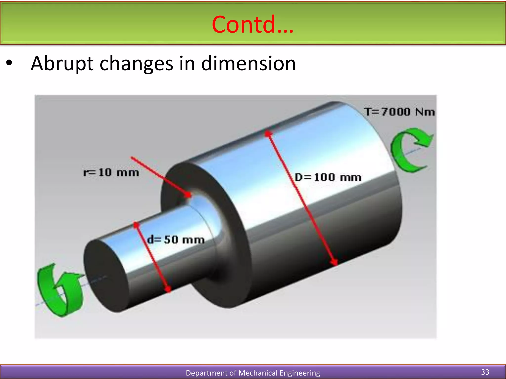
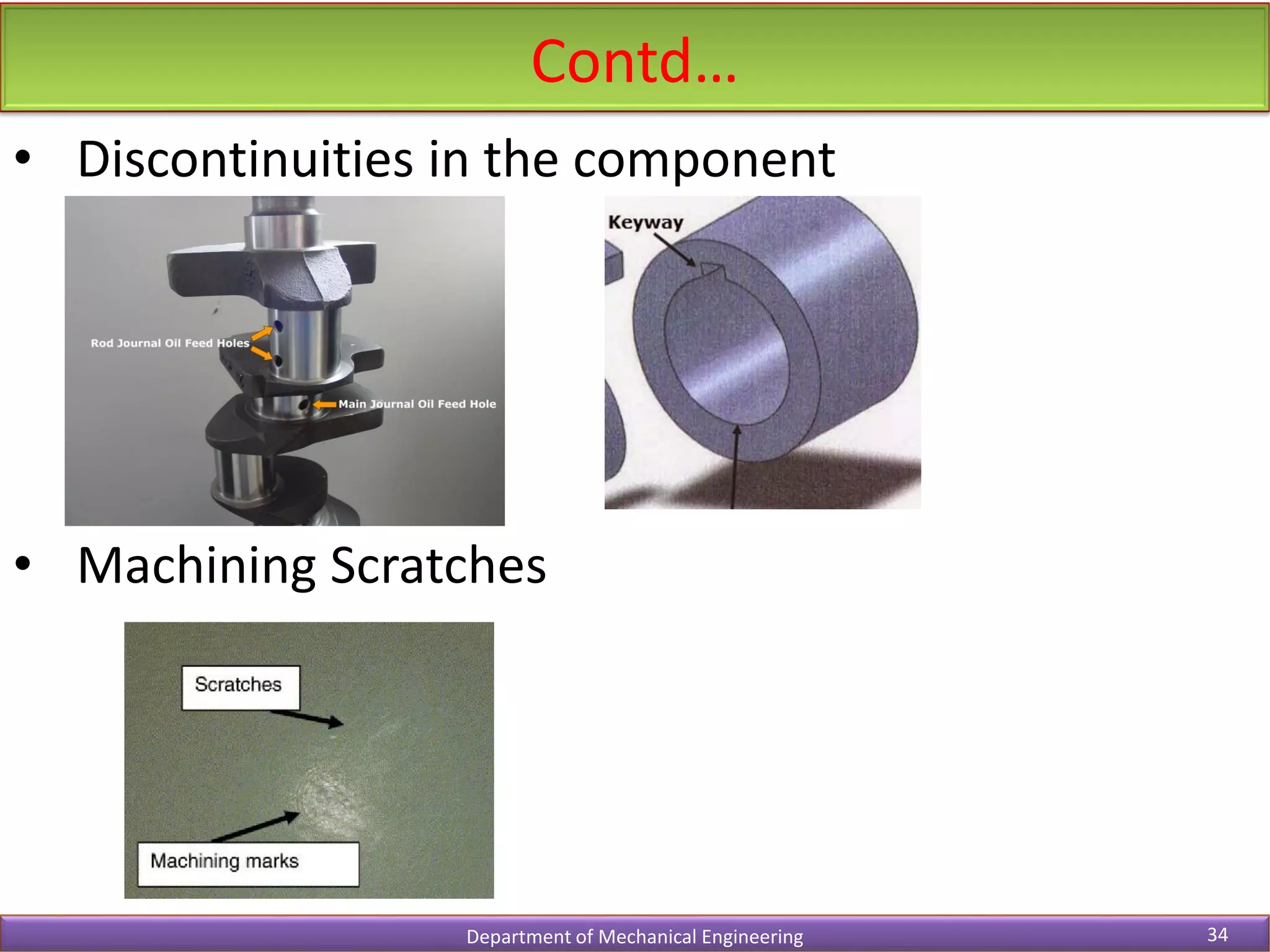
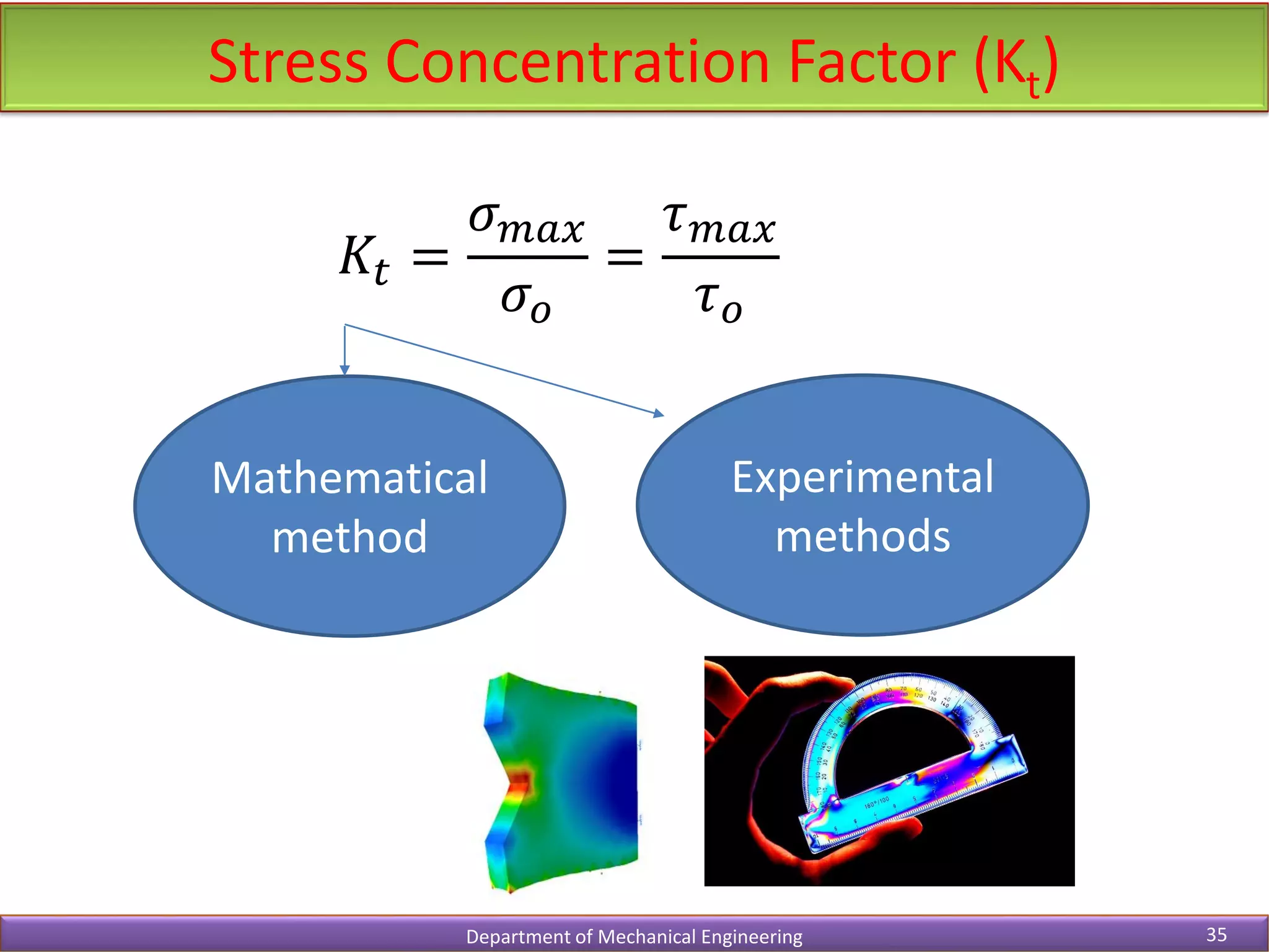
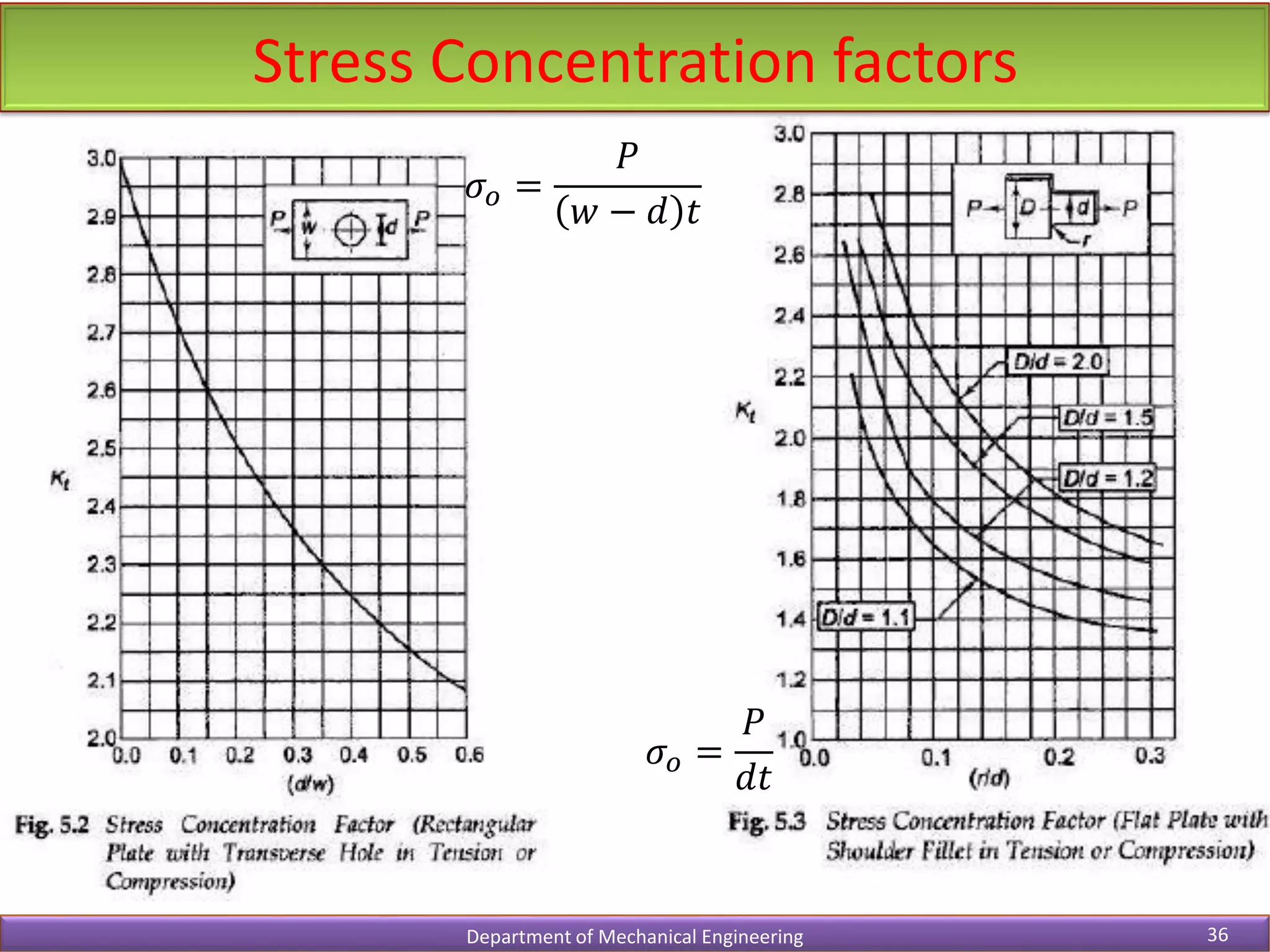
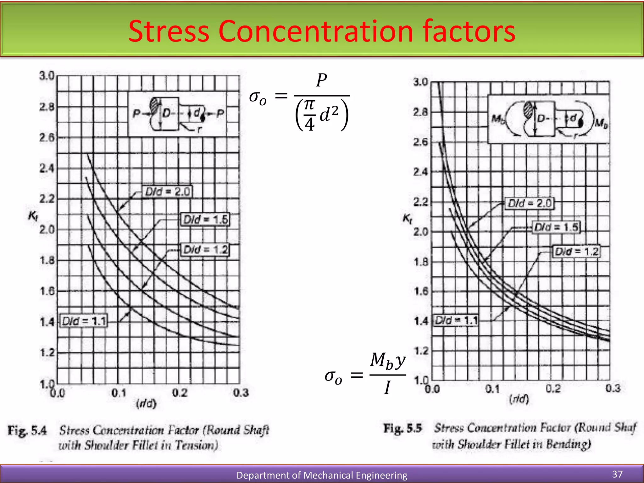
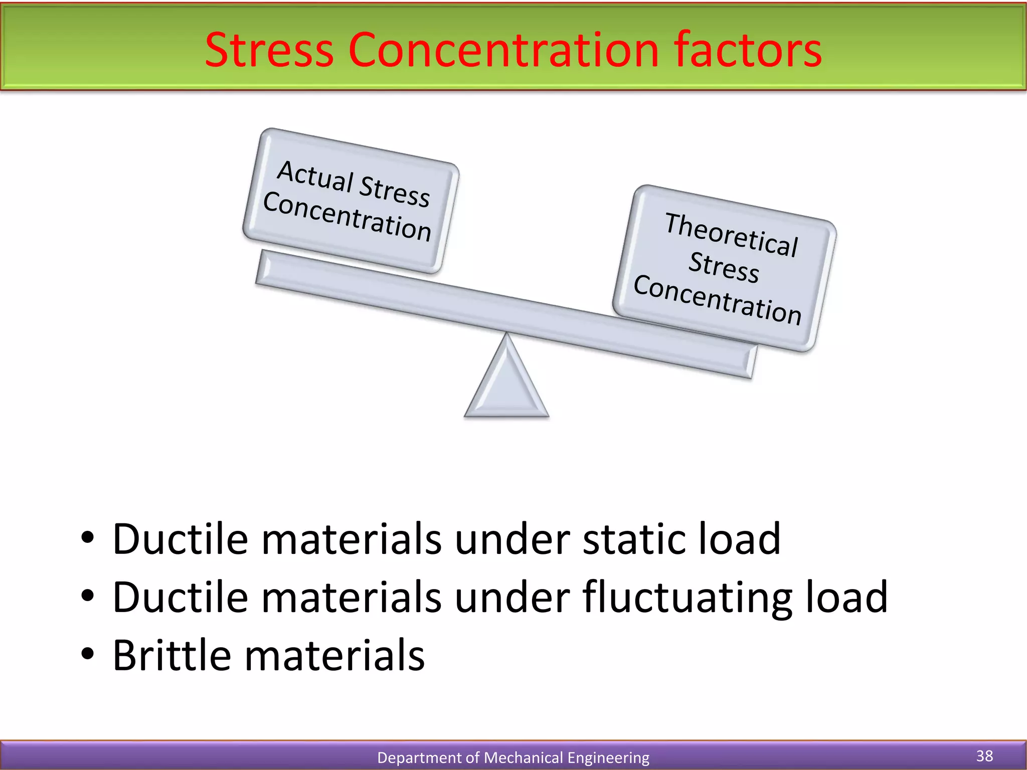
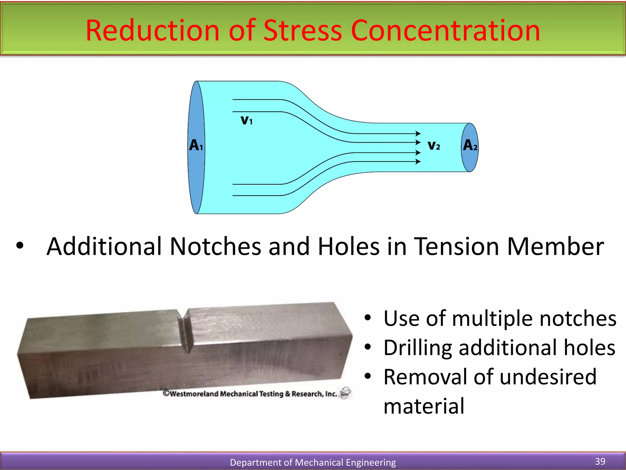
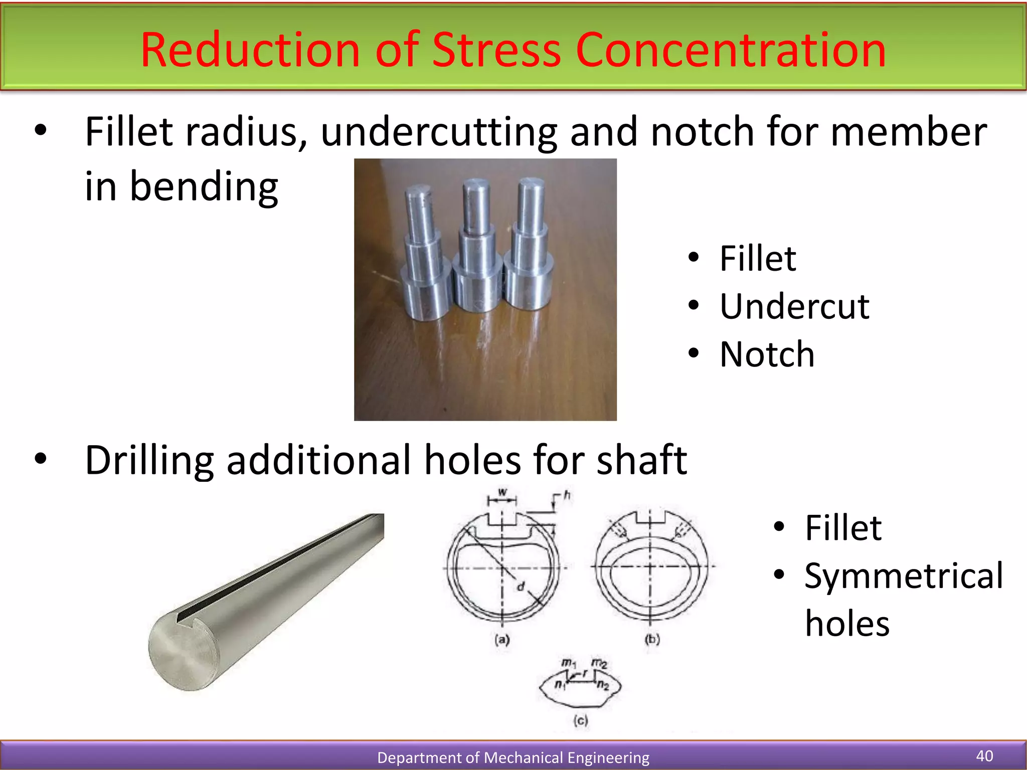
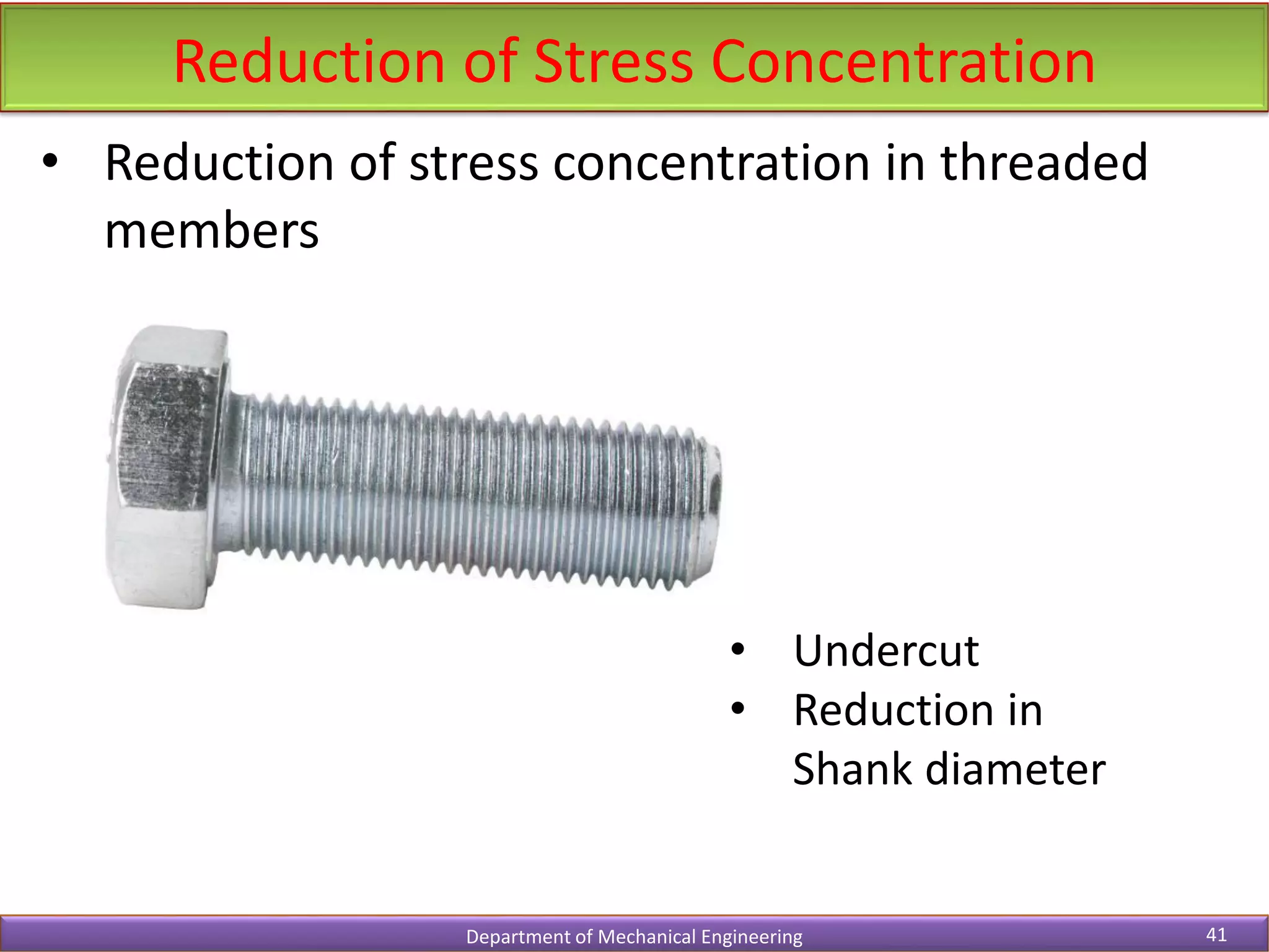
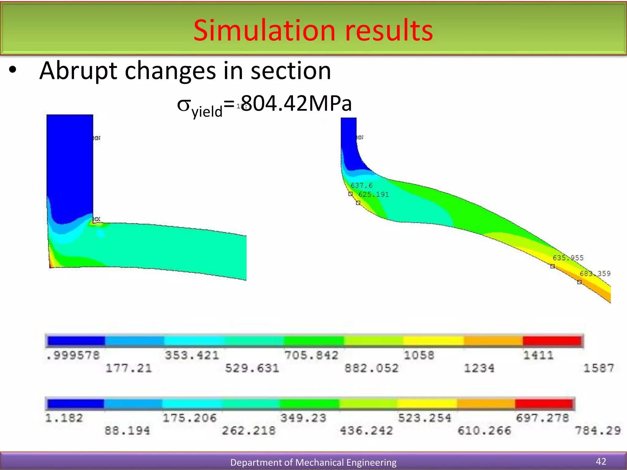
- Examples and diagrams are provided to explain concepts like stress concentration and its reduction.