design of machine elements and members in mechanical engineering
1.
D E SI G N O F M A C H I N E E L E M E N T S
CH. D. JAYATEJA M.Tech, (Ph.D.)
Assistant Professor
Department of Mechanical Engineering
2.
SYLLABUS
• UNIT –IINTRODUCTION: General considerations in the design of Engineering
Materials and their properties – selection –Manufacturing consideration in design,
tolerances and fits –BIS codes of steels. STRESSES IN MACHINE MEMBERS: Simple
stresses – combined stresses – torsional and bending stresses – impact stresses –
stress strain relation – various theories of failure – factor of safety – design for strength
and rigidity – preferred numbers.The concept of stiffness in tension, bending, torsion
and combined situations-Applications on static design-Cotter joint, Knuckle joint, Spigot
joint
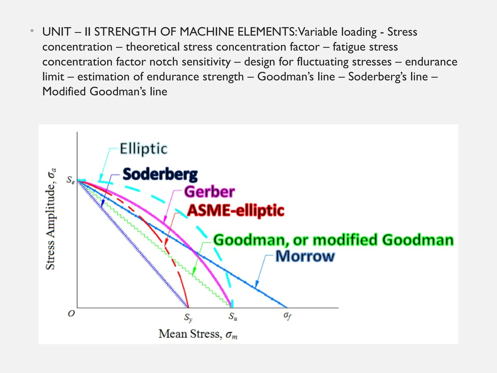
• UNIT – II STRENGTH OF MACHINE ELEMENTS:Variable loading - Stress
concentration – theoretical stress concentration factor – fatigue stress concentration
factor notch sensitivity – design for fluctuating stresses – endurance limit – estimation
of endurance strength – Goodman’s line – Soderberg’s line – Modified Goodman’s line.
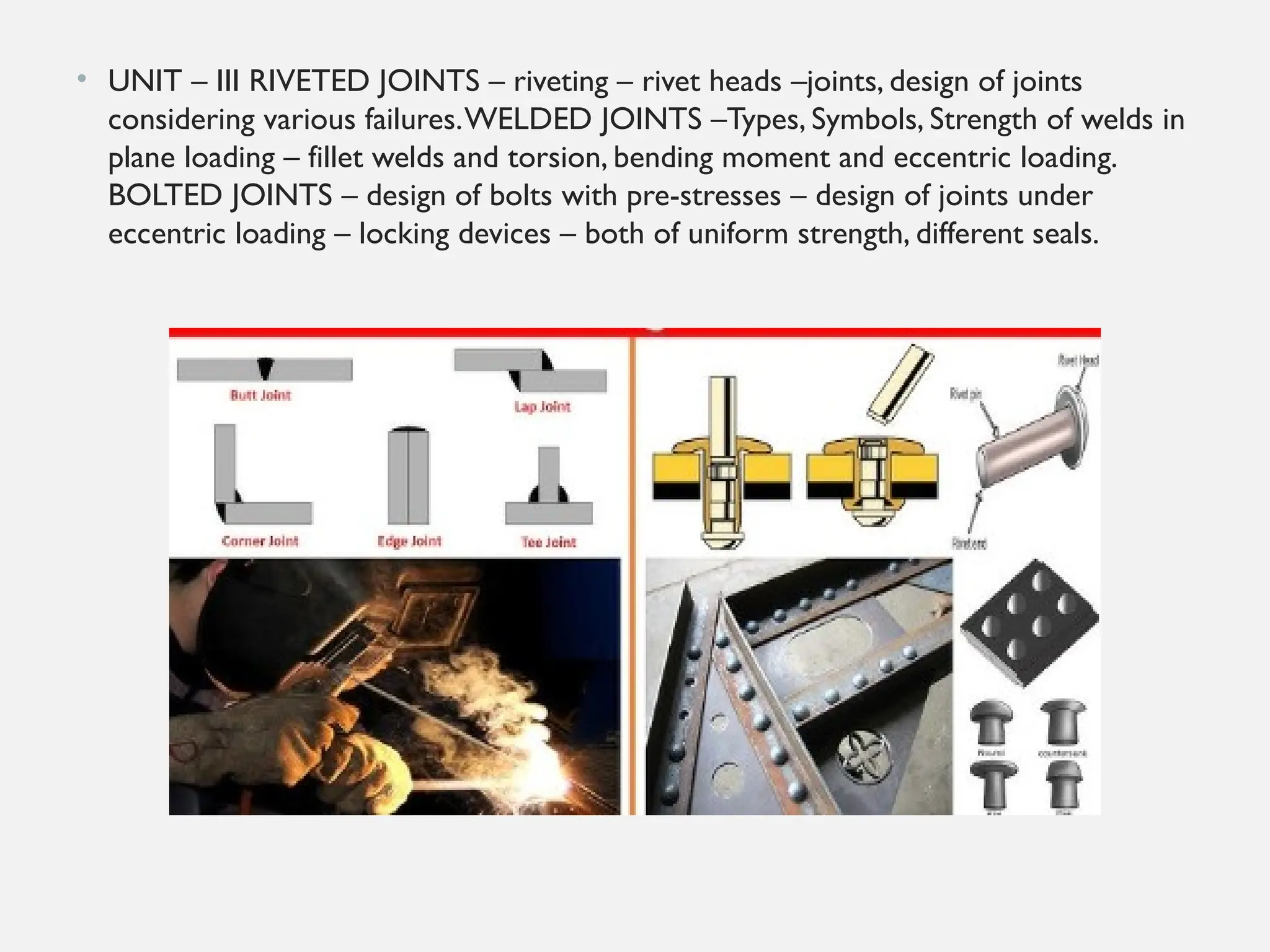
• UNIT – III RIVETED JOINTS – riveting – rivet heads –joints, design of joints
considering various failures.WELDED JOINTS –Types, Symbols, Strength of welds in
plane loading – fillet welds and torsion, bending moment and eccentric loading.
BOLTED JOINTS – design of bolts with pre-stresses – design of joints under eccentric
loading – locking devices – both of uniform strength, different seals.
3.
Text Books:
1. MachineDesign/V. Bandari/TMH Publishers
2. Machine design / P. Kannaiah/SCITECH Publications (India) Pvt. Ltd.
3. Machine Design –Norton/ Pearson publishers
References:
1. Design of Machine Elements /V.M. Faires/McMillan
2. Machine design / Schaum Series/Mc Graw Hill Professional
3. Machine Design/ Shigley, J.E/McGraw Hill.
4. Design data handbook/ K. Mahadevan& K. Balaveera Reddy/ CBS publishers.
5. Design of machine elements-Spotts/Pearson Publications.
Course outcomes:
• At the end of the course, student will be able to
• CO1: Judge about materials and their properties along with manufacturing considerations.
• CO2: Gain knowledge about the strength of machine elements.
• CO3:Apply the knowledge in designing the riveted and welded joints, keys, cotters and knuckle joints.
• CO4:Apply the knowledge in designing the shafts and shaft couplings.
• CO5:Apply the knowledge in designing the mechanical springs.
4.
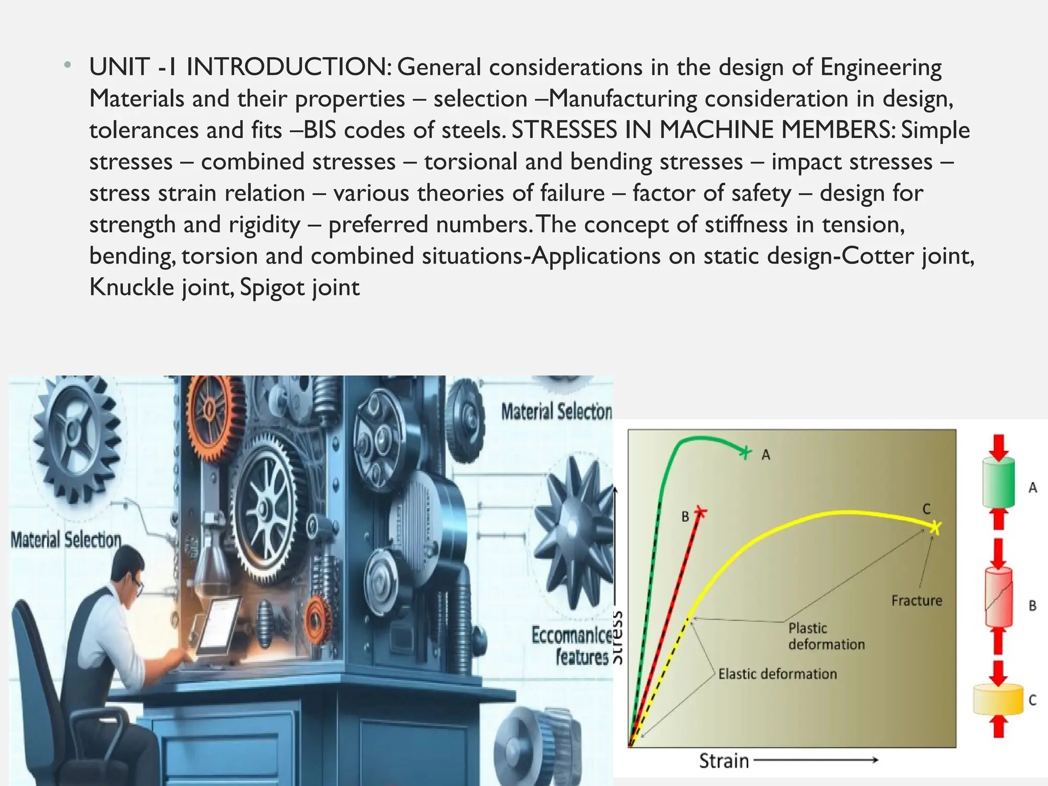
• UNIT -1INTRODUCTION: General considerations in the design of Engineering
Materials and their properties – selection –Manufacturing consideration in design,
tolerances and fits –BIS codes of steels. STRESSES IN MACHINE MEMBERS: Simple
stresses – combined stresses – torsional and bending stresses – impact stresses –
stress strain relation – various theories of failure – factor of safety – design for
strength and rigidity – preferred numbers.The concept of stiffness in tension,
bending, torsion and combined situations-Applications on static design-Cotter joint,
Knuckle joint, Spigot joint
5.
• UNIT –II STRENGTH OF MACHINE ELEMENTS:Variable loading - Stress
concentration – theoretical stress concentration factor – fatigue stress
concentration factor notch sensitivity – design for fluctuating stresses – endurance
limit – estimation of endurance strength – Goodman’s line – Soderberg’s line –
Modified Goodman’s line
6.
• UNIT –III RIVETED JOINTS – riveting – rivet heads –joints, design of joints
considering various failures.WELDED JOINTS –Types, Symbols, Strength of welds in
plane loading – fillet welds and torsion, bending moment and eccentric loading.
BOLTED JOINTS – design of bolts with pre-stresses – design of joints under
eccentric loading – locking devices – both of uniform strength, different seals.
7.
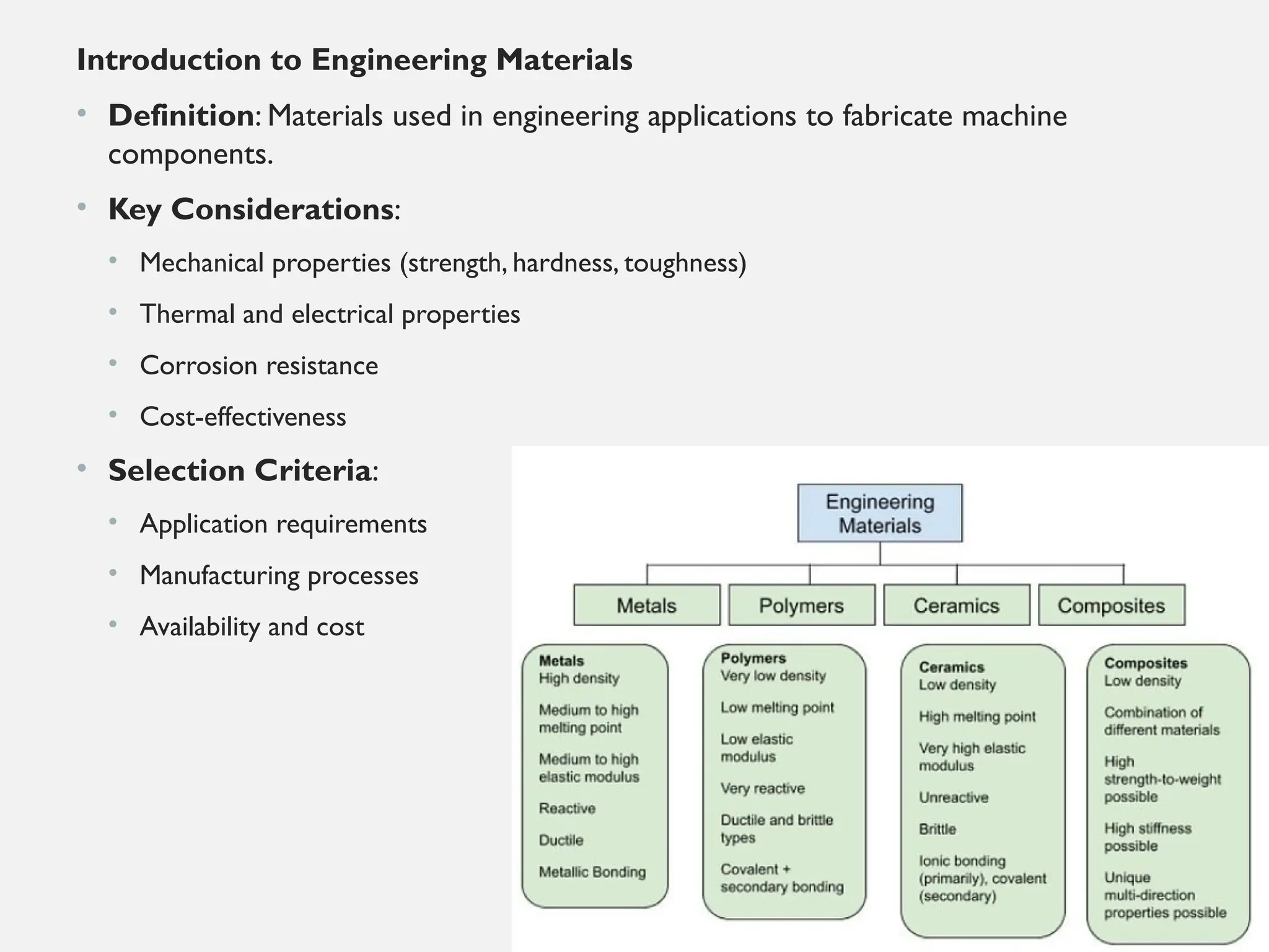
Introduction to EngineeringMaterials
• Definition: Materials used in engineering applications to fabricate machine
components.
• Key Considerations:
• Mechanical properties (strength, hardness, toughness)
• Thermal and electrical properties
• Corrosion resistance
• Cost-effectiveness
• Selection Criteria:
• Application requirements
• Manufacturing processes
• Availability and cost
8.
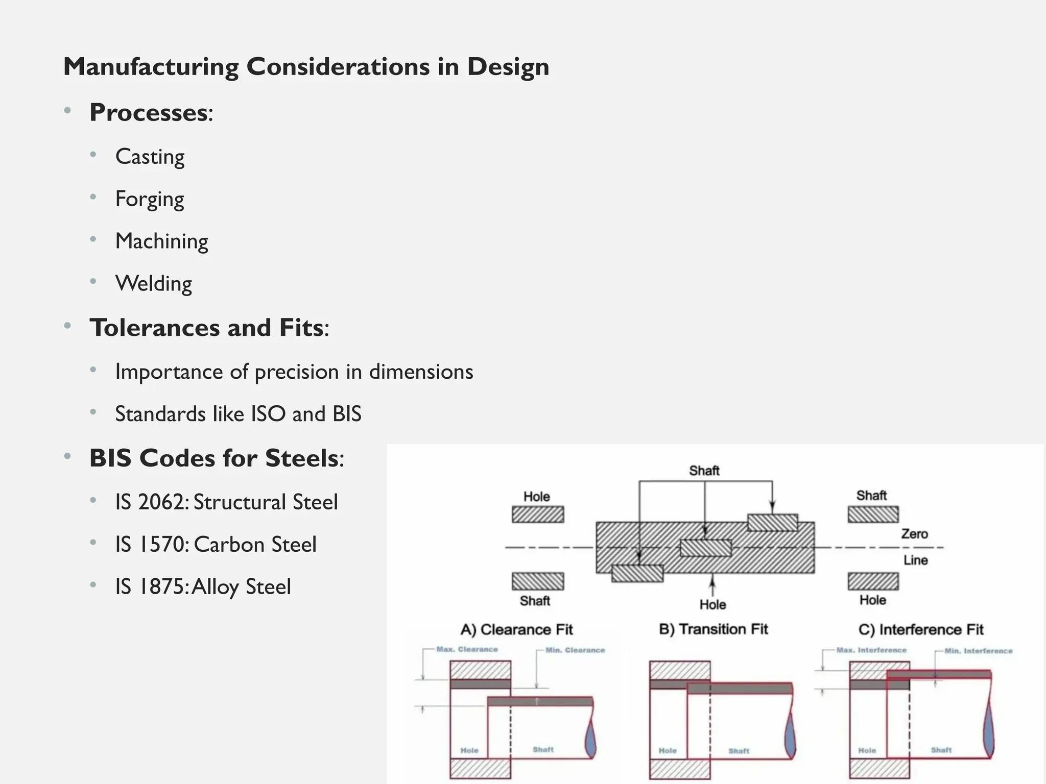
Manufacturing Considerations inDesign
• Processes:
• Casting
• Forging
• Machining
• Welding
• Tolerances and Fits:
• Importance of precision in dimensions
• Standards like ISO and BIS
• BIS Codes for Steels:
• IS 2062: Structural Steel
• IS 1570: Carbon Steel
• IS 1875:Alloy Steel
9.
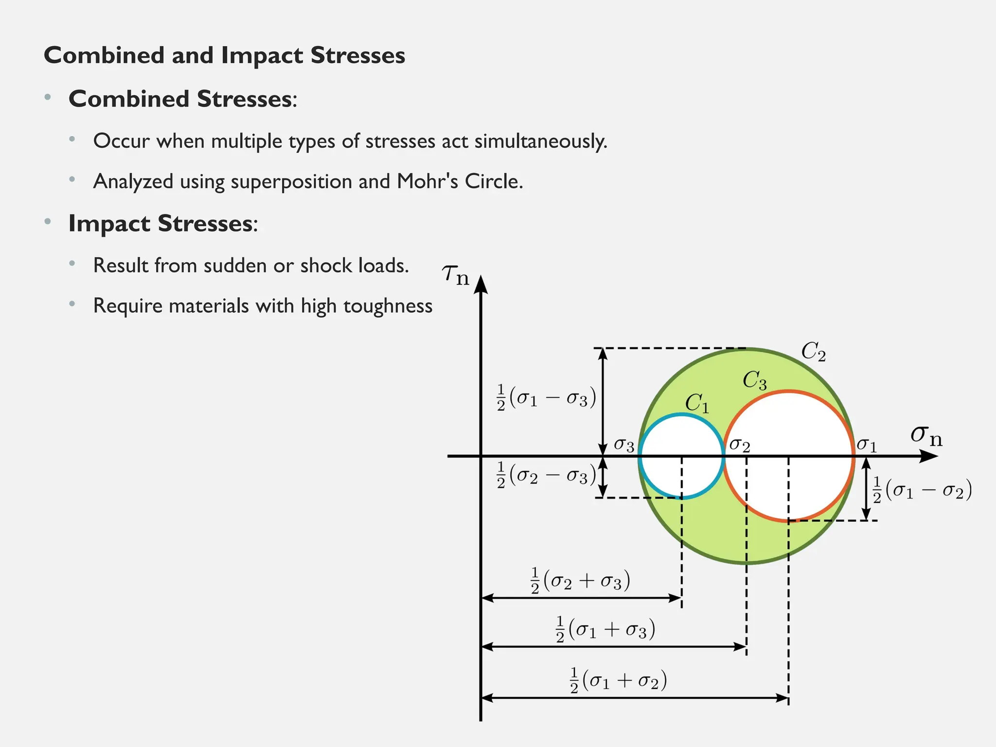
Combined and ImpactStresses
• Combined Stresses:
• Occur when multiple types of stresses act simultaneously.
• Analyzed using superposition and Mohr's Circle.
• Impact Stresses:
• Result from sudden or shock loads.
• Require materials with high toughness
10.
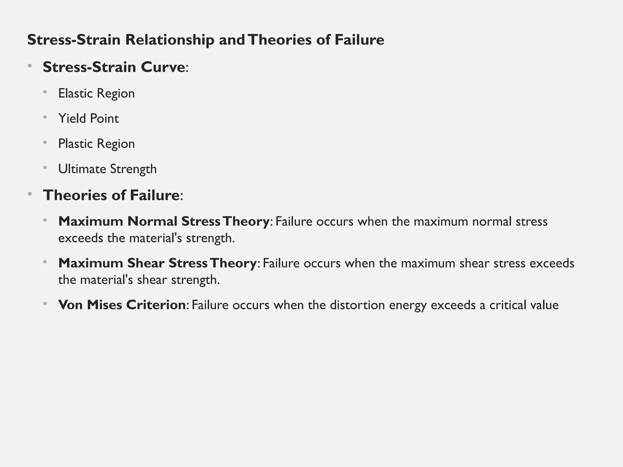
Stress-Strain Relationship andTheoriesof Failure
• Stress-Strain Curve:
• Elastic Region
• Yield Point
• Plastic Region
• Ultimate Strength
• Theories of Failure:
• Maximum Normal StressTheory: Failure occurs when the maximum normal stress
exceeds the material's strength.
• Maximum Shear StressTheory: Failure occurs when the maximum shear stress exceeds
the material's shear strength.
• Von Mises Criterion: Failure occurs when the distortion energy exceeds a critical value
11.
• Factor ofSafety and Stiffness
• Factor of Safety (FoS):
• FoS = Material Strength / Design Stress
• Ensures reliability and accounts for uncertainties.
• Stiffness:
• Resistance to deformation.
• Depends on material properties and geometry.
• Calculated as k=F/δ
k = is force and = is displacement
δ
12.
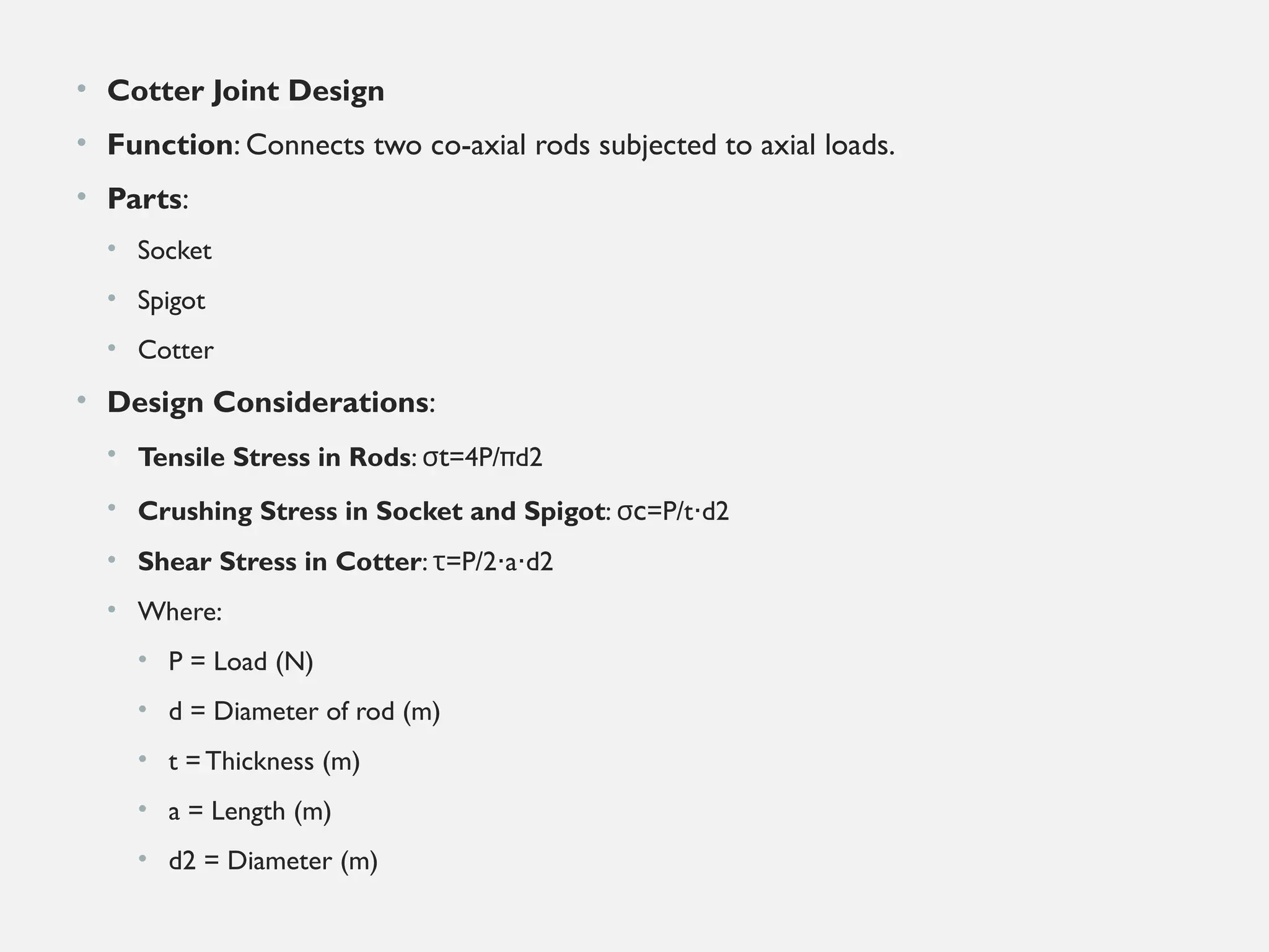
• Cotter JointDesign
• Function: Connects two co-axial rods subjected to axial loads.
• Parts:
• Socket
• Spigot
• Cotter
• Design Considerations:
• Tensile Stress in Rods: σt=4P/πd2
• Crushing Stress in Socket and Spigot: σc=P/t d2
⋅
• Shear Stress in Cotter: =
τ P/2 a d2
⋅ ⋅
• Where:
• P = Load (N)
• d = Diameter of rod (m)
• t = Thickness (m)
• a = Length (m)
• d2= Diameter (m)
13.
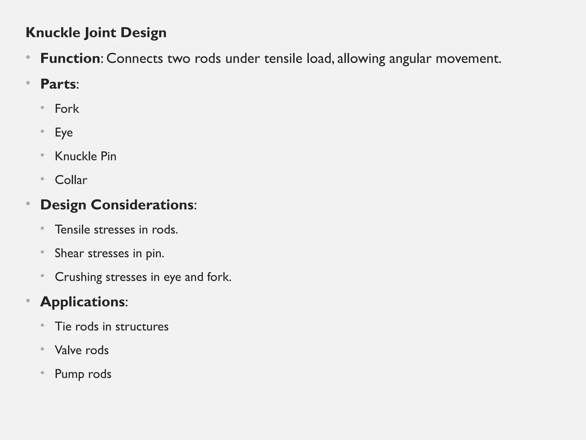
Knuckle Joint Design
•Function: Connects two rods under tensile load, allowing angular movement.
• Parts:
• Fork
• Eye
• Knuckle Pin
• Collar
• Design Considerations:
• Tensile stresses in rods.
• Shear stresses in pin.
• Crushing stresses in eye and fork.
• Applications:
• Tie rods in structures
• Valve rods
• Pump rods
14.
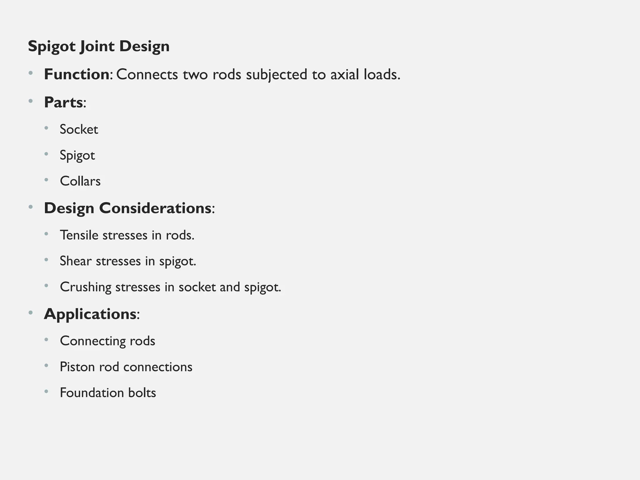
Spigot Joint Design
•Function: Connects two rods subjected to axial loads.
• Parts:
• Socket
• Spigot
• Collars
• Design Considerations:
• Tensile stresses in rods.
• Shear stresses in spigot.
• Crushing stresses in socket and spigot.
• Applications:
• Connecting rods
• Piston rod connections
• Foundation bolts
15.
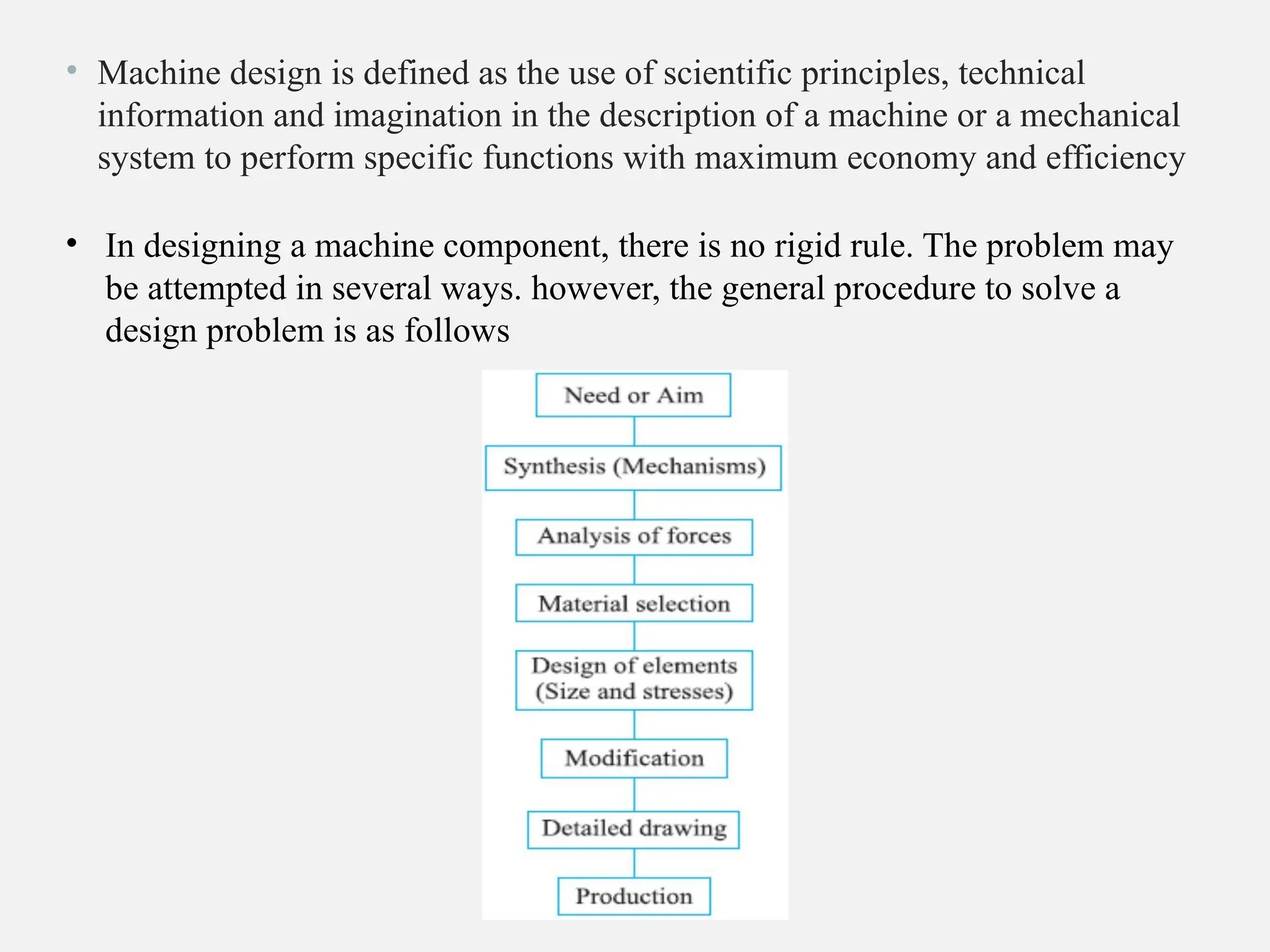
• Machine designis defined as the use of scientific principles, technical
information and imagination in the description of a machine or a mechanical
system to perform specific functions with maximum economy and efficiency
• In designing a machine component, there is no rigid rule. The problem may
be attempted in several ways. however, the general procedure to solve a
design problem is as follows
16.
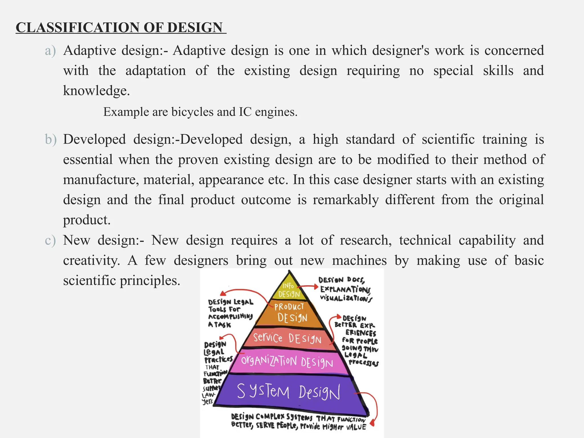
CLASSIFICATION OF DESIGN
a)Adaptive design:- Adaptive design is one in which designer's work is concerned
with the adaptation of the existing design requiring no special skills and
knowledge.
Example are bicycles and IC engines.
b) Developed design:-Developed design, a high standard of scientific training is
essential when the proven existing design are to be modified to their method of
manufacture, material, appearance etc. In this case designer starts with an existing
design and the final product outcome is remarkably different from the original
product.
c) New design:- New design requires a lot of research, technical capability and
creativity. A few designers bring out new machines by making use of basic
scientific principles.
17.
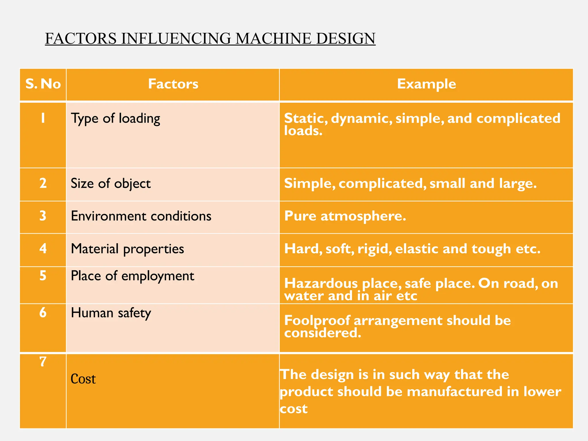
S. No FactorsExample
1 Type of loading Static, dynamic, simple, and complicated
loads.
2 Size of object Simple, complicated, small and large.
3 Environment conditions Pure atmosphere.
4 Material properties Hard, soft, rigid, elastic and tough etc.
5 Place of employment
Hazardous place, safe place. On road, on
water and in air etc
6 Human safety
Foolproof arrangement should be
considered.
7
Cost The design is in such way that the
product should be manufactured in lower
cost
FACTORS INFLUENCING MACHINE DESIGN
18.
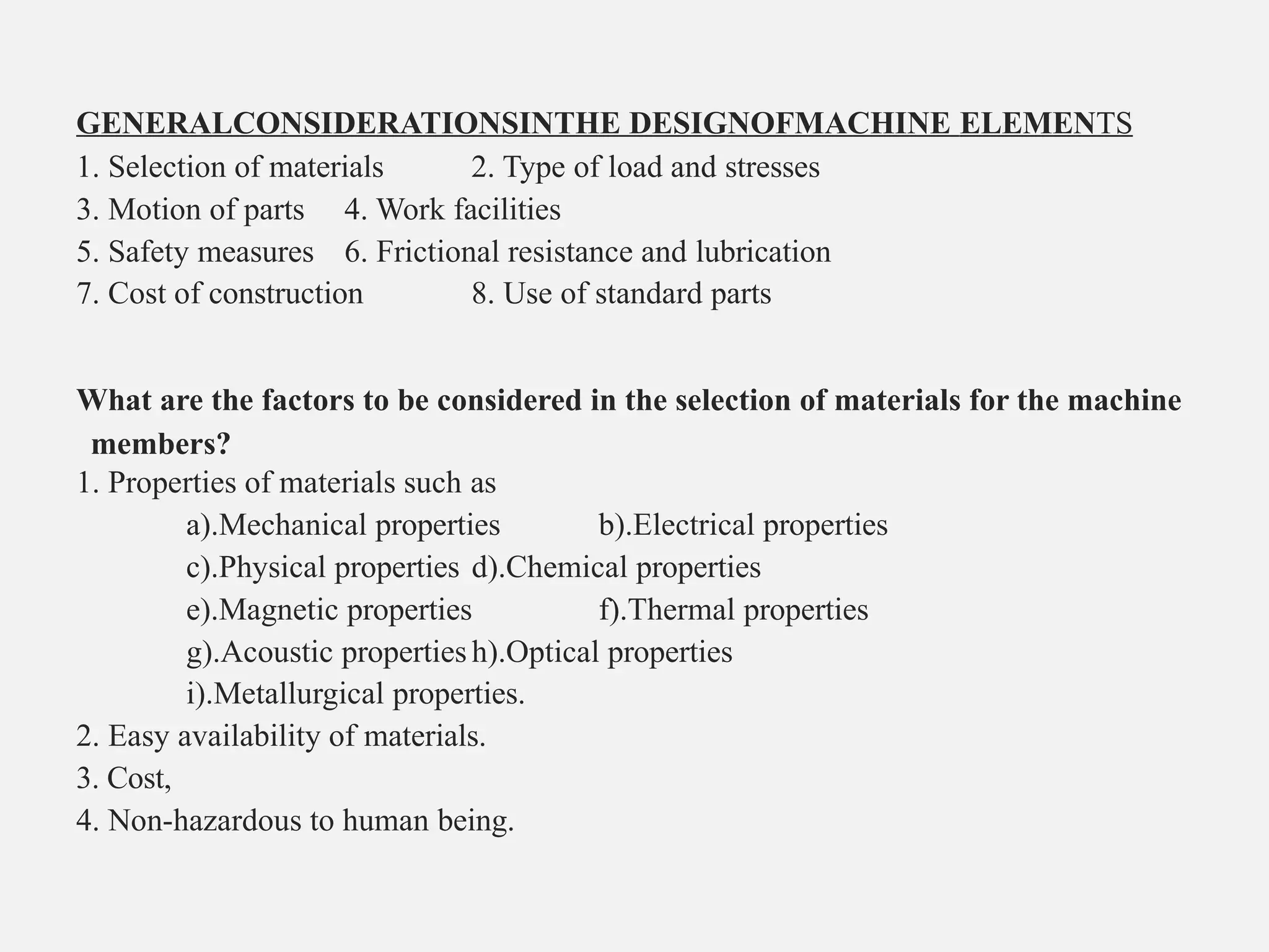
GENERALCONSIDERATIONSINTHE DESIGNOFMACHINE ELEMENTS
1.Selection of materials 2. Type of load and stresses
3. Motion of parts 4. Work facilities
5. Safety measures 6. Frictional resistance and lubrication
7. Cost of construction 8. Use of standard parts
What are the factors to be considered in the selection of materials for the machine
members?
1. Properties of materials such as
a).Mechanical properties b).Electrical properties
c).Physical properties d).Chemical properties
e).Magnetic properties f).Thermal properties
g).Acoustic properties h).Optical properties
i).Metallurgical properties.
2. Easy availability of materials.
3. Cost,
4. Non-hazardous to human being.
20.
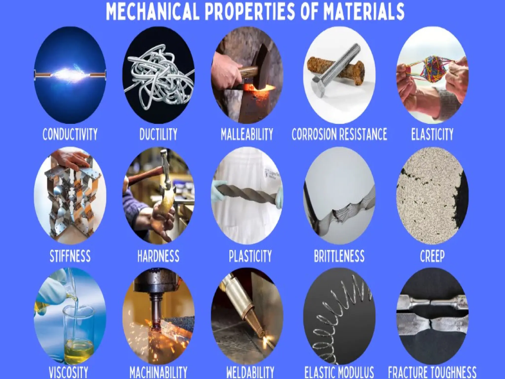
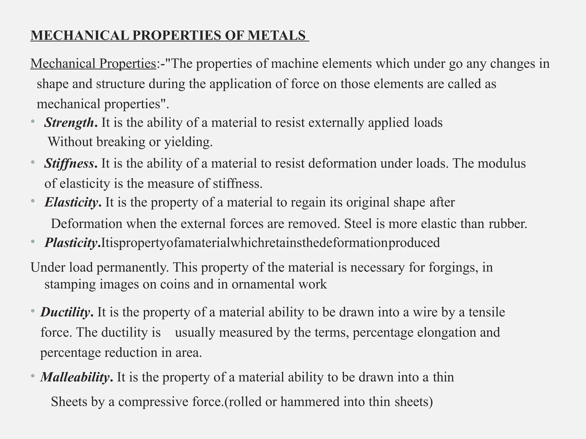
MECHANICAL PROPERTIES OFMETALS
Mechanical Properties:-"The properties of machine elements which under go any changes in
shape and structure during the application of force on those elements are called as
mechanical properties".
• Strength. It is the ability of a material to resist externally applied loads
Without breaking or yielding.
• Stiffness. It is the ability of a material to resist deformation under loads. The modulus
of elasticity is the measure of stiffness.
• Elasticity. It is the property of a material to regain its original shape after
Deformation when the external forces are removed. Steel is more elastic than rubber.
• Plasticity.Itispropertyofamaterialwhichretainsthedeformationproduced
Under load permanently. This property of the material is necessary for forgings, in
stamping images on coins and in ornamental work
• Ductility. It is the property of a material ability to be drawn into a wire by a tensile
force. The ductility is usually measured by the terms, percentage elongation and
percentage reduction in area.
• Malleability. It is the property of a material ability to be drawn into a thin
Sheets by a compressive force.(rolled or hammered into thin sheets)
21.
• Brittleness: suddenbreaking with minimum distortion. Cast iron is a brittle material.
• Toughness. It is the property of a material to resist fracture due to high
Impact loads like hammer blows. The toughness of the material decreases when it is heated.
• Resilience. Is defined as the ability of the material to absorb energy when
deformed elastically and to release this energy when unloaded. This property is essential for
spring materials.
• Creep. The slow and progressive deformation with time. IC engines,
boilers, turbines blades, rocket engines, and nuclear reactor components etc are subjected to
creep.
• Fatigue. When a material is subjected to repeated stresses, it fails at Stresses below the yield
point stresses. Such type of failure of a material is known as fatigue.
• Or Ability to with stand cyclic stresses.
This property is considered in designing shafts, connecting rods, springs, gears, etc.
• Hardness–resistance to wear, scratching, deformation, machinability etc
The hardness of a metal may be determined by the following tests:
Brinell hardness test,
Rockwell hardness test,
•Vickers hardness(also called Diamond Pyramid)test, and
22.
The following factorsshould be considered while selecting the material :
• Availability of the materials
• Suitability of the materials for the working conditions in service, and
• The cost of the materials.
•The important properties, which determine the utility of the material are physical,
chemical and mechanical properties.
23.
METALS AND THEIRALLOYS: -
Cast Iron: -
1. Cast iron is an alloy of iron & carbon, containing more than 2% of carbon Typical composition
of ordinary cast iron is: Carbon = 3-4% Silicon = 1-3% Manganese = 0.5-1%
Sulphur = up to 0.1% Phosphorous = up to 0.1% Iron = Remain.
The different types of cast irons are White cast iron, Malleable cast iron, Grey cast iron, Spheroidal cast
iron, chilled cast iron and Alloy cast iron.
Advantages:
Available in large quantities
Higher compressive strength,
Components can be given any complex shape with out involving costly machining
operations,
Excellent ability to damp vibrations,
More resistance to wear even under the conditions of boundary lubrication,
Mechanical properties of parts do not change between room temperature and
3500centigrade
Disadvantages:
It has poor tensile strength compared to steel
Cast iron does not offer any plastic deformation before failure
Cast iron is brittle material
The machinability of cast iron parts is poor compared to steel.
Applications:
Machine tool Beds, lathe bed and guide ways
Automotive components, agricultural components, feed pipe fittings
Piston, piston rings, camshafts, pulleys and gears
Agricultural tractors, implement parts in automotive crank shafts, piston and cylinder heads
24.
Steel:-
It is analloy of iron and carbon, with carboncontentuptoamaximumof1.5%.
Classifications:-
Dead mild steel—upto0.15%carbon
Low carbon or mild steel — 0.15% to 0.45% carbon (Good ductility, good formability)
Medium carbon steel — 0.45% to 0.8% carbon (High hardness than low carbon steel)
High carbon steel—0.8%to1.5%carbon(Good wear and operation resistance)
Applications:-
Carbon 0.1 to 0.2% Tubing, forgings, pressed steel parts, rivets and screws. Carbon 0.2 to 0.3% Forged and
machine parts, structural members, boilers. Carbon0.3to 0.55%Forgedandmachine parts, automobile bolts, shafts.
Carbon 0.55 to 0.75%Rails, hammers. Carbon0.75to0.85%Coilsandflatsprings.
Carbon0.85to0.95%Tools, punches, dies and saws.
Effects of various elements in steel
Carbon:-Increasing in carbon content up to 0.83% increase the ultimate strength. If the carbon content is going to
be more than 0.83% reduces the strength, hardeness, ductility and weldability.
• Silicon:- Silicon is added in spring steel to increase its toughness.
• Manganese:-Manganese increases, hardness and ultimate strength increases.
• Nickel:-Nickel increases strength, hardness and toughness increases.
• Chromium:-Chromium increases hardness & wear resistance, steel containing more than 4% chromium have
excellent corrosion resistance
Applications:-
Stampings, rivets, cams, gears, levers,
Screws, nets, dies and screw drivers, washers
Handsaw, springs, chisels and ball bearings
25.
High Speed ToolSteels
These steels are used for cutting metals at a much higher cutting speed than ordinary carbon tool steels.
The carbon steel cutting tools do not retain their sharp cutting edges under heavier loads and higher
speeds.
Most of the high-speed steels contain tungsten as the chief alloying element, but other elements like
cobalt, chromium, vanadium, etc. may be present in some proportion. Following are the different types of
high-speed steels:
1. High speed steel. This steel, on an average, contains18%oftungsten, 4% of chromium and 1%
vanadium. Itis considered to be one of the best of all purpose tool steels. It is widely used for drills,
lathe, planer and shaper tools, milling cutters, reamers, broaches, threading dies, punches, etc.
2. Molybdenum high speed steel. This steel, on an average, contains 6%of
tungsten, 6% of molybdenum, 4% of chromium and 2% of vanadium. It has excellent toughness and
cutting ability. The molybdenum high speed steels are better and cheaper than other types of steels. It is
particularly used for drilling and tapping operations.
• Super high speed steel. This steel is also called cobalt high speed steel
becausecobaltisaddedfrom2to15%,in order to increase the cutting efficiency especially at high
temperatures.
This steel, on an average, contains 20% tungsten, 4% chromium, 2% vanadium and 12% cobalt. Since the
cost of this steel is more, therefore, it is principally used for heavy cutting operations which impose high
pressure and temperatures on the tool.
Duralumin is an Al-Cu-Mg-Mn alloy (94%Al–4%Cu–1% Mg–1%Mn)and it has good corrosion
resistance and strength. It is strong, hard and light weight alloy of aluminium. It is widely used in aircraft
construction.
26.
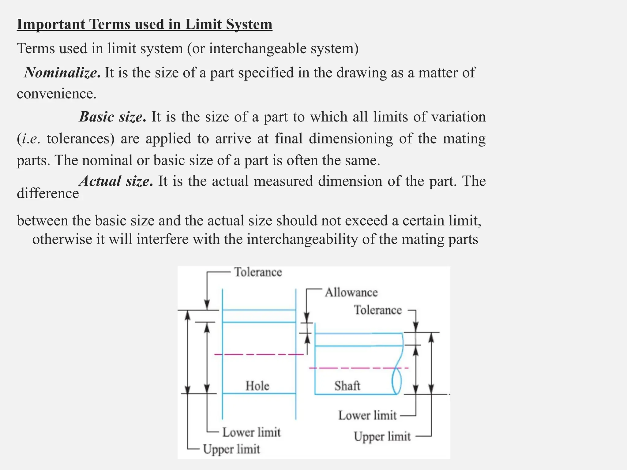
Important Terms usedin Limit System
Terms used in limit system (or interchangeable system)
Nominalize. It is the size of a part specified in the drawing as a matter of
convenience.
Basic size. It is the size of a part to which all limits of variation
(i.e. tolerances) are applied to arrive at final dimensioning of the mating
parts. The nominal or basic size of a part is often the same.
Actual size. It is the actual measured dimension of the part. The
difference
between the basic size and the actual size should not exceed a certain limit,
otherwise it will interfere with the interchangeability of the mating parts
27.
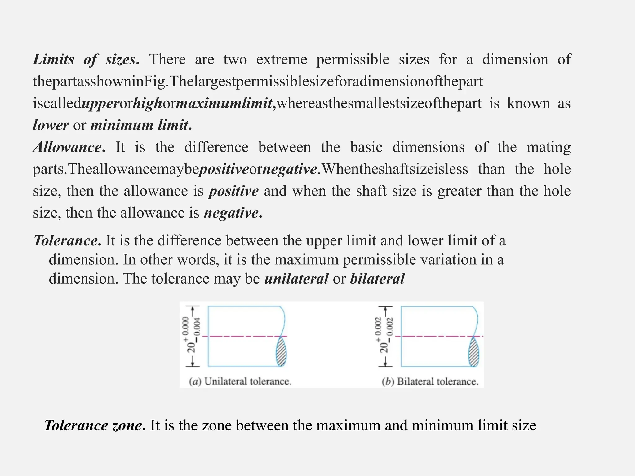
Limits of sizes.There are two extreme permissible sizes for a dimension of
thepartasshowninFig.Thelargestpermissiblesizeforadimensionofthepart
iscalledupperorhighormaximumlimit,whereasthesmallestsizeofthepart is known as
lower or minimum limit.
Allowance. It is the difference between the basic dimensions of the mating
parts.Theallowancemaybepositiveornegative.Whentheshaftsizeisless than the hole
size, then the allowance is positive and when the shaft size is greater than the hole
size, then the allowance is negative.
Tolerance. It is the difference between the upper limit and lower limit of a
dimension. In other words, it is the maximum permissible variation in a
dimension. The tolerance may be unilateral or bilateral
Tolerance zone. It is the zone between the maximum and minimum limit size
28.
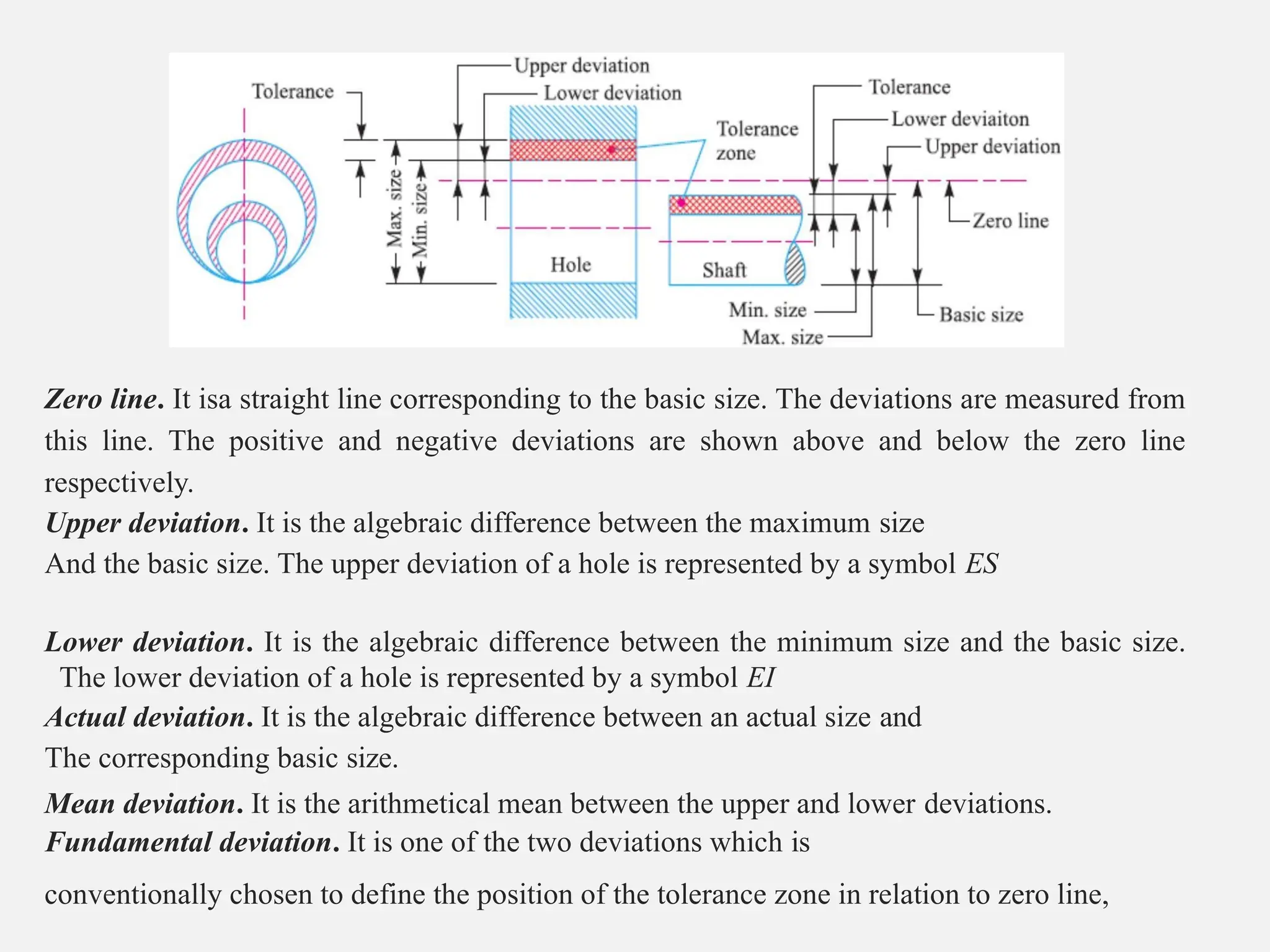
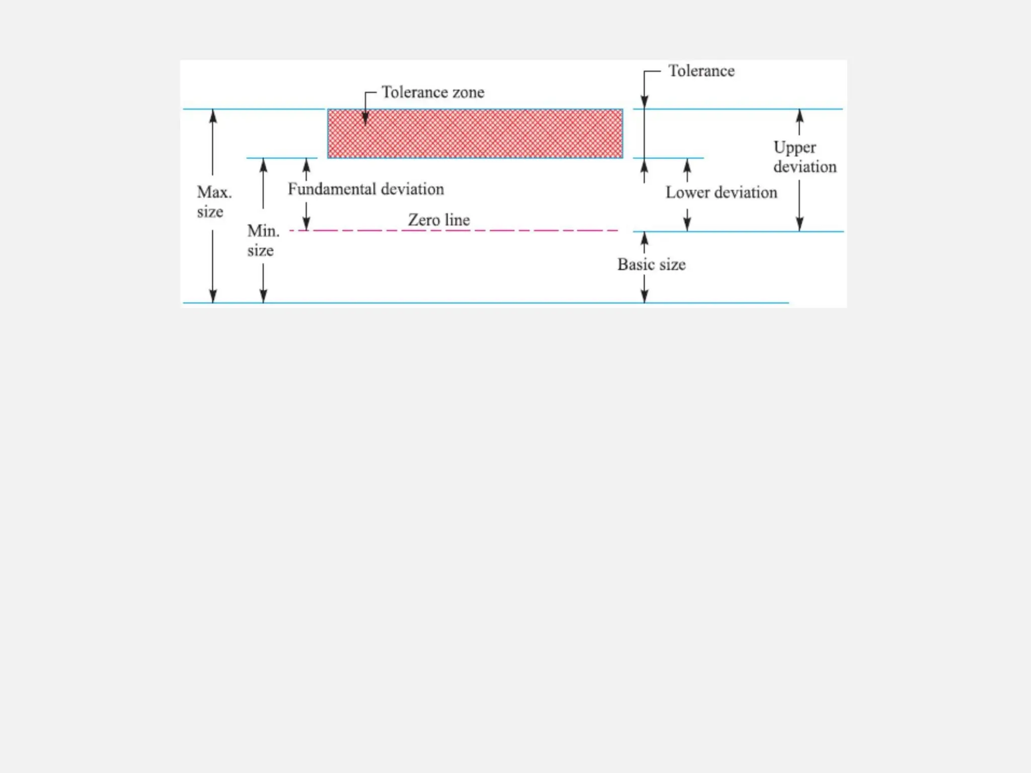
Zero line. Itisa straight line corresponding to the basic size. The deviations are measured from
this line. The positive and negative deviations are shown above and below the zero line
respectively.
Upper deviation. It is the algebraic difference between the maximum size
And the basic size. The upper deviation of a hole is represented by a symbol ES
Lower deviation. It is the algebraic difference between the minimum size and the basic size.
The lower deviation of a hole is represented by a symbol EI
Actual deviation. It is the algebraic difference between an actual size and
The corresponding basic size.
Mean deviation. It is the arithmetical mean between the upper and lower deviations.
Fundamental deviation. It is one of the two deviations which is
conventionally chosen to define the position of the tolerance zone in relation to zero line,
30.
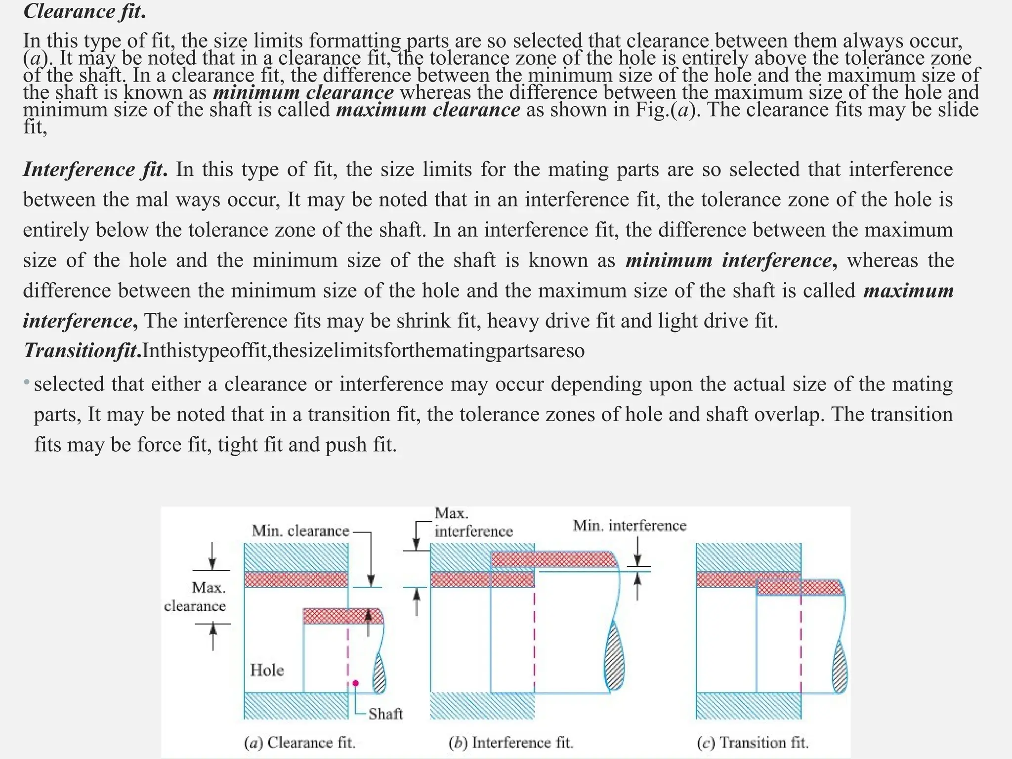
Clearance fit.
In thistype of fit, the size limits formatting parts are so selected that clearance between them always occur,
(a). It may be noted that in a clearance fit, the tolerance zone of the hole is entirely above the tolerance zone
of the shaft. In a clearance fit, the difference between the minimum size of the hole and the maximum size of
the shaft is known as minimum clearance whereas the difference between the maximum size of the hole and
minimum size of the shaft is called maximum clearance as shown in Fig.(a). The clearance fits may be slide
fit,
Interference fit. In this type of fit, the size limits for the mating parts are so selected that interference
between the mal ways occur, It may be noted that in an interference fit, the tolerance zone of the hole is
entirely below the tolerance zone of the shaft. In an interference fit, the difference between the maximum
size of the hole and the minimum size of the shaft is known as minimum interference, whereas the
difference between the minimum size of the hole and the maximum size of the shaft is called maximum
interference, The interference fits may be shrink fit, heavy drive fit and light drive fit.
Transitionfit.Inthistypeoffit,thesizelimitsforthematingpartsareso
•selected that either a clearance or interference may occur depending upon the actual size of the mating
parts, It may be noted that in a transition fit, the tolerance zones of hole and shaft overlap. The transition
fits may be force fit, tight fit and push fit.
31.
Basis of LimitSystem
1. Hole basis system. When the hole is kept as a constant member (i.e. when the
lower deviation of the hole is zero) and different fits are obtained by varying the
shaft size, as shown in Fig.(a), then the limit system is said to be on a hole basis.
2. Shaft basis system. When the shaft is kept as a constant member(i.e. when
•The upper deviation of the shaft is zero)and different fits are obtained by varying the
hole size, .(b),then the limit system is said to be on a shaft basis.
32.
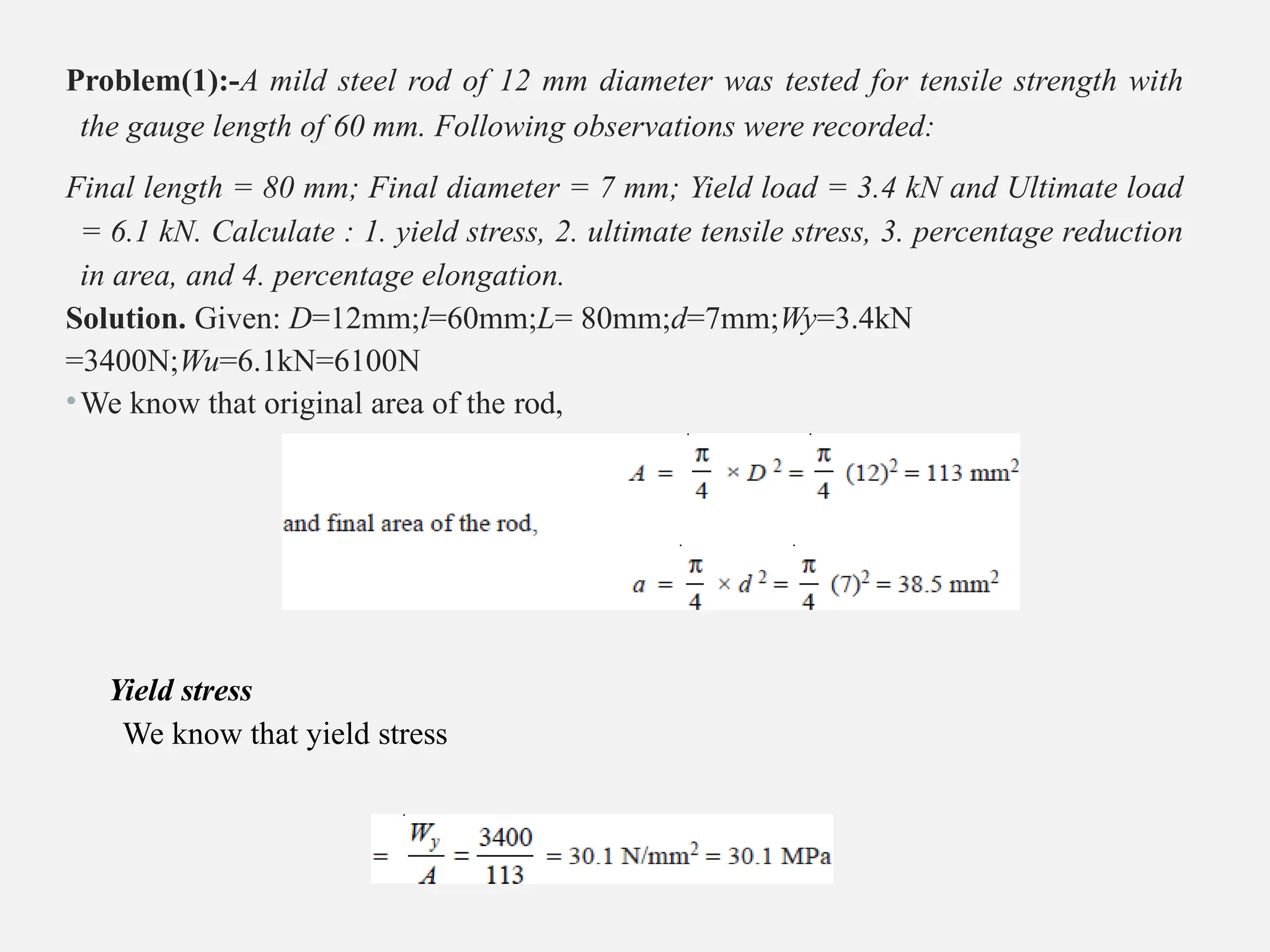
Problem(1):-A mild steelrod of 12 mm diameter was tested for tensile strength with
the gauge length of 60 mm. Following observations were recorded:
Final length = 80 mm; Final diameter = 7 mm; Yield load = 3.4 kN and Ultimate load
= 6.1 kN. Calculate : 1. yield stress, 2. ultimate tensile stress, 3. percentage reduction
in area, and 4. percentage elongation.
Solution. Given: D=12mm;l=60mm;L= 80mm;d=7mm;Wy=3.4kN
=3400N;Wu=6.1kN=6100N
•We know that original area of the rod,
Yield stress
We know that yield stress
33.
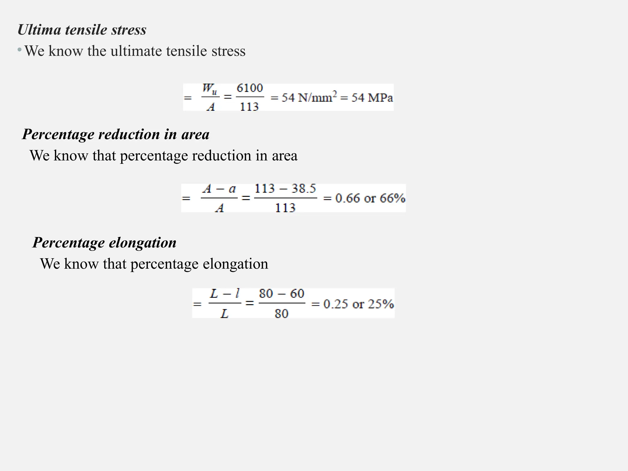
Ultima tensile stress
•Weknow the ultimate tensile stress
Percentage reduction in area
We know that percentage reduction in area
Percentage elongation
We know that percentage elongation
34.
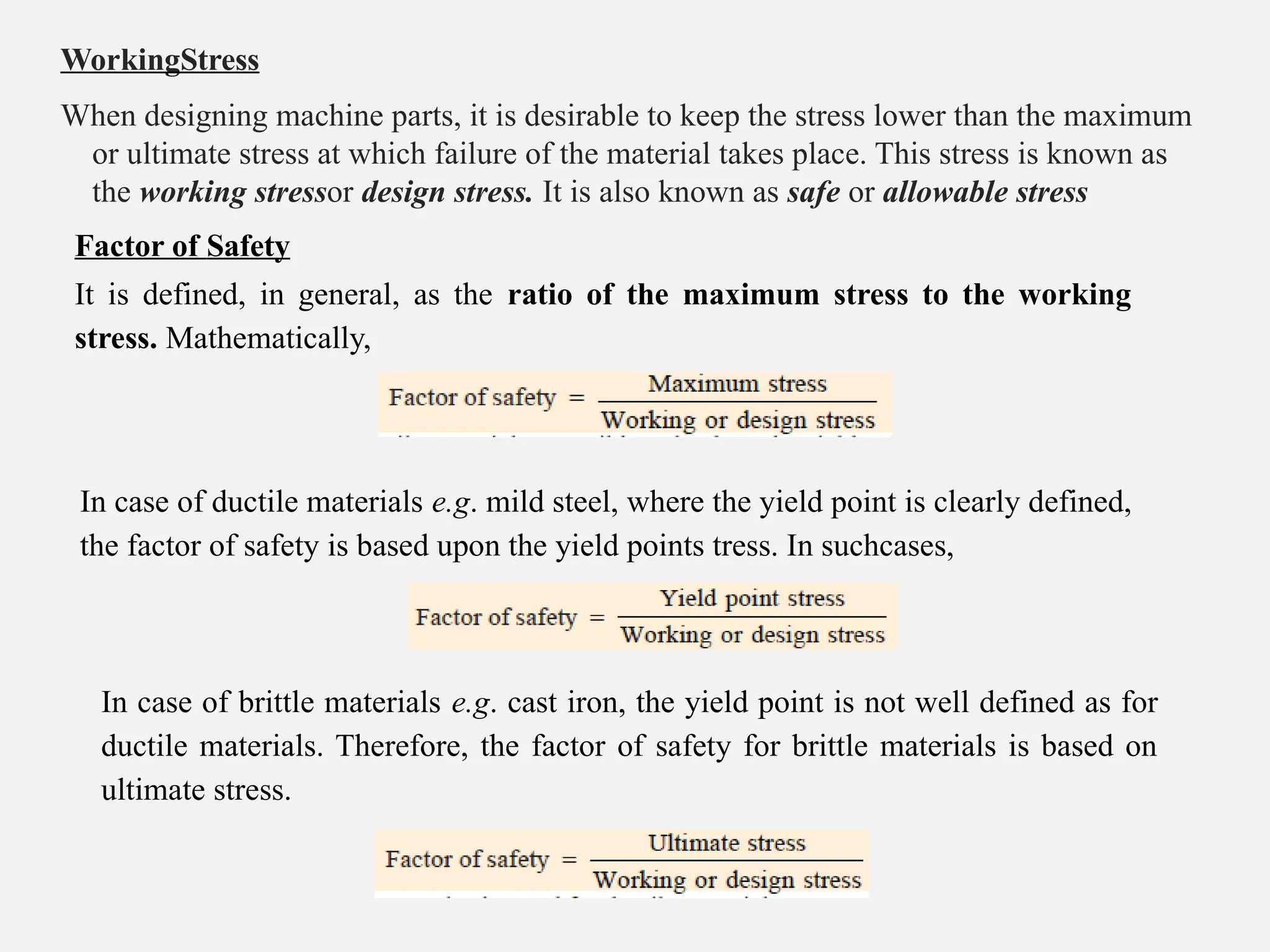
WorkingStress
When designing machineparts, it is desirable to keep the stress lower than the maximum
or ultimate stress at which failure of the material takes place. This stress is known as
the working stressor design stress. It is also known as safe or allowable stress
Factor of Safety
It is defined, in general, as the ratio of the maximum stress to the working
stress. Mathematically,
In case of ductile materials e.g. mild steel, where the yield point is clearly defined,
the factor of safety is based upon the yield points tress. In suchcases,
In case of brittle materials e.g. cast iron, the yield point is not well defined as for
ductile materials. Therefore, the factor of safety for brittle materials is based on
ultimate stress.
35.
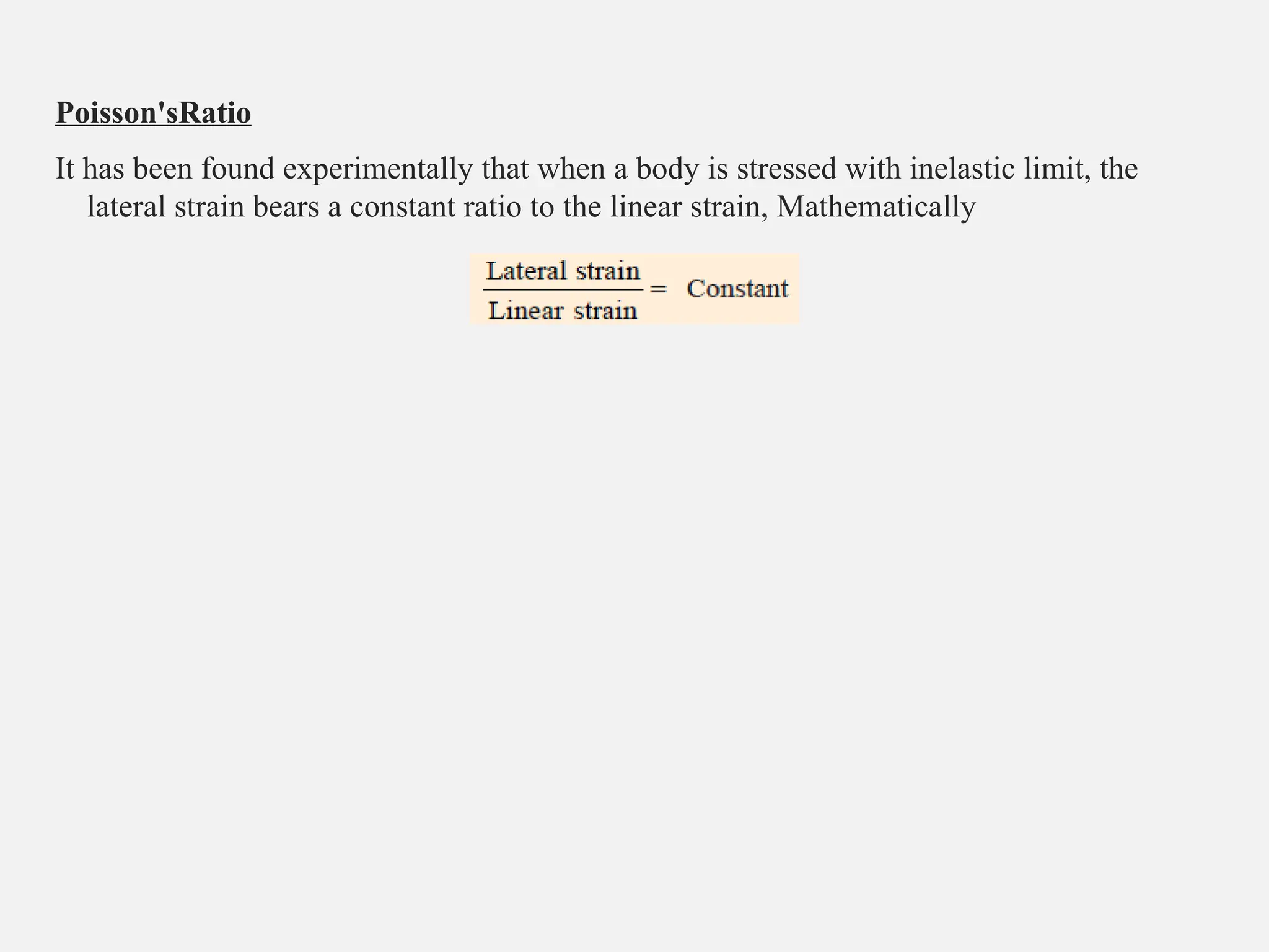
Poisson'sRatio
It has beenfound experimentally that when a body is stressed with inelastic limit, the
lateral strain bears a constant ratio to the linear strain, Mathematically
36.
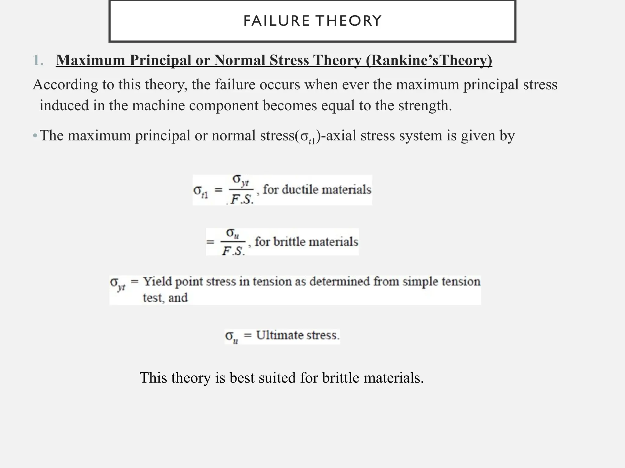
FAILURE THEORY
1. MaximumPrincipal or Normal Stress Theory (Rankine’sTheory)
According to this theory, the failure occurs when ever the maximum principal stress
induced in the machine component becomes equal to the strength.
•The maximum principal or normal stress(σt1)-axial stress system is given by
This theory is best suited for brittle materials.
37.
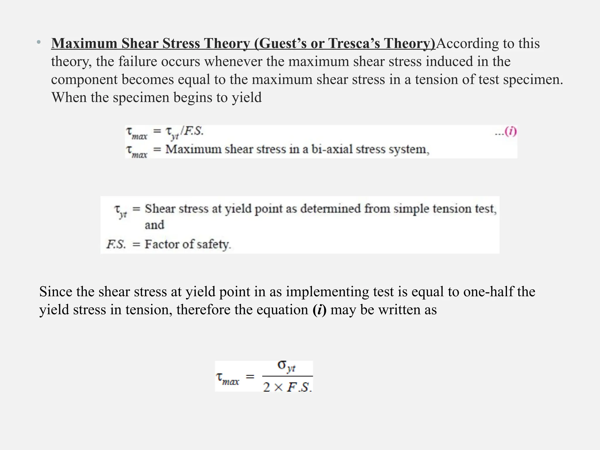
• Maximum ShearStress Theory (Guest’s or Tresca’s Theory)According to this
theory, the failure occurs whenever the maximum shear stress induced in the
component becomes equal to the maximum shear stress in a tension of test specimen.
When the specimen begins to yield
Since the shear stress at yield point in as implementing test is equal to one-half the
yield stress in tension, therefore the equation (i) may be written as