Download as PDF, PPTX
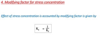
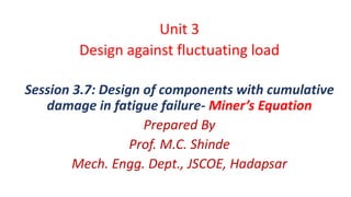
![Unit 3
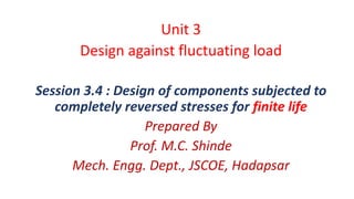
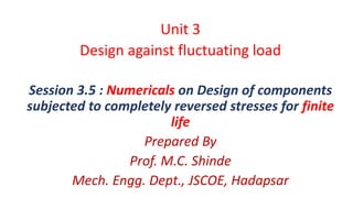
Design against fluctuating load
Prepared By
Prof. M.C. Shinde[9970160753]
Mech. Engg. Dept., JSCOE, Hadapsar](https://image.slidesharecdn.com/unit3r1-210628092728/85/Unit-3-Design-of-Fluctuating-Loads-1-320.jpg)
![Unit 3
Design against fluctuating load
Prepared By
Prof. M.C. Shinde[9970160753]
Mech. Engg. Dept., JSCOE, Hadapsar](https://image.slidesharecdn.com/unit3r1-210628092728/75/Unit-3-Design-of-Fluctuating-Loads-1-2048.jpg)


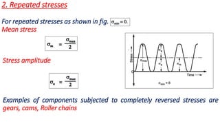


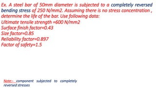
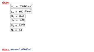


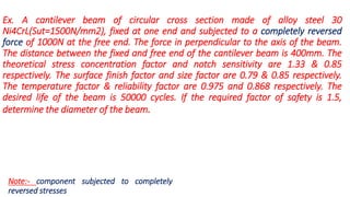
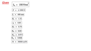
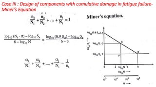
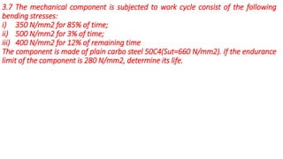
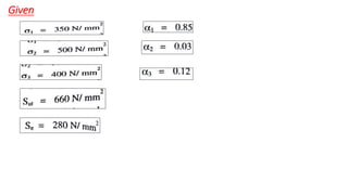
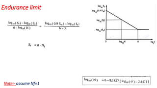
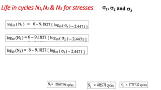
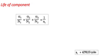

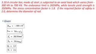

Given: Stresses: i) 350 N/mm2 for 85% of time ii) 500 N/mm2 for 3% of time iii) 400 N/mm2 for 12% of remaining time Material: Plain carbon steel 50C Using Miner's rule: For stress i) N1/Nf1 = 0.85 Where, N1 is no. of cycles component can withstand at stress 350 N/mm2 Nf1 is no. of cycles to failure at stress 350 N/mm2 Similarly, for other stresses: N2/Nf2 = 0.03 N3/Nf3 = 0.12 Equ


