The document discusses the OSI model and data link layer. It provides details on:
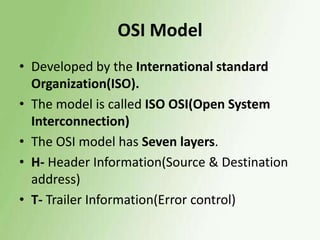
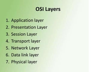
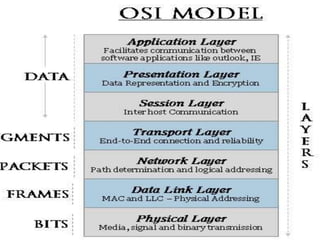
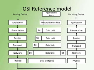
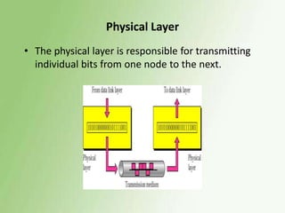
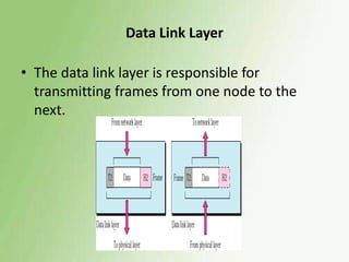
1) The OSI model has 7 layers, with the data link layer responsible for transmitting frames between nodes and handling functions like framing, flow control, and error control.
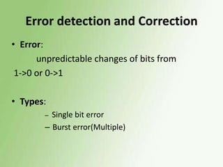
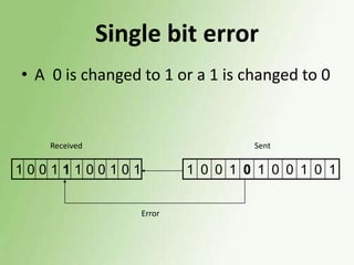
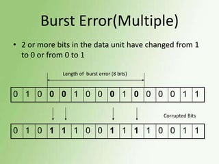
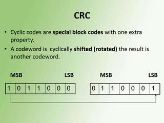
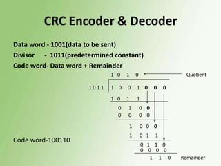
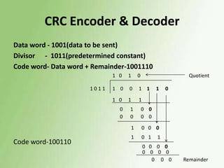
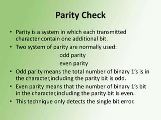
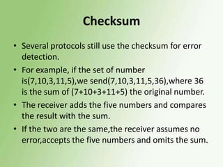
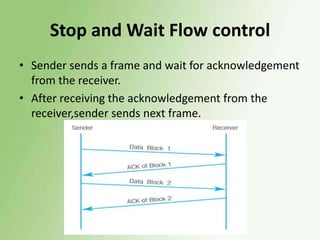
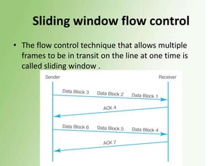
2) Error detection techniques discussed include CRC, parity checks, and checksums. Flow control methods like stop-and-wait and sliding windows are also covered.
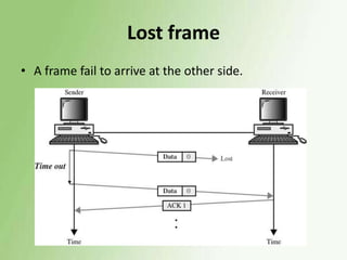
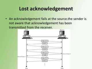
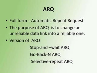
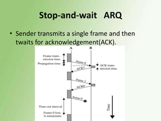
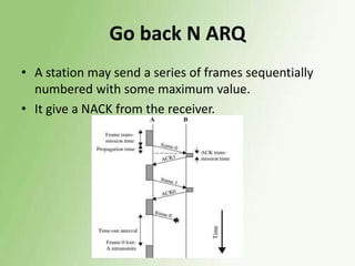
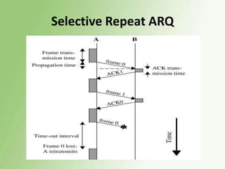
3) Error control uses techniques like ARQ to recover corrupted data, with examples of stop-and-wait, go-back-N, and selective repeat ARQ provided.