This document provides an overview of various computer networking concepts including:
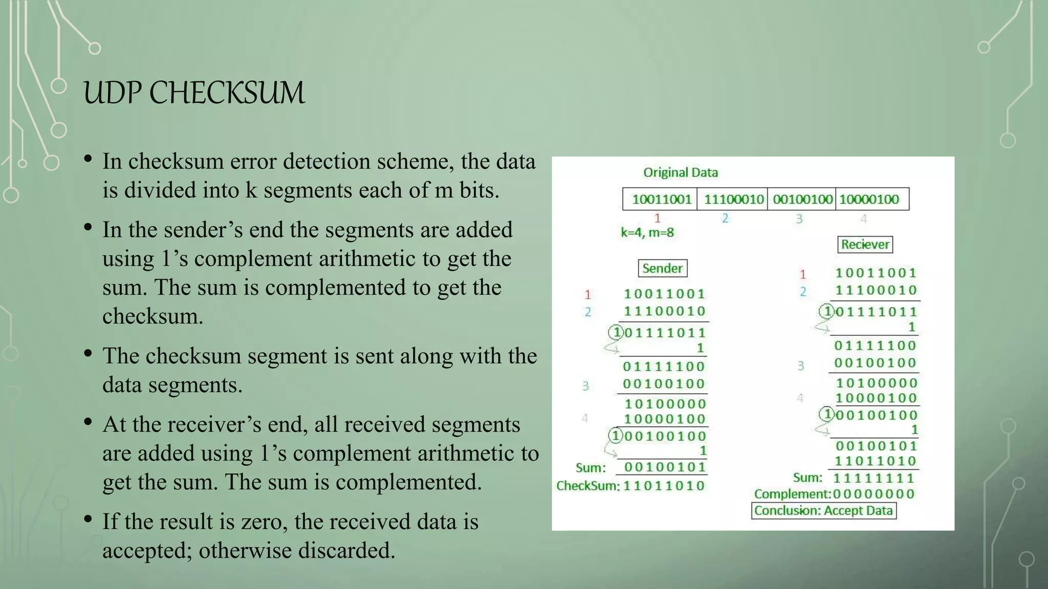
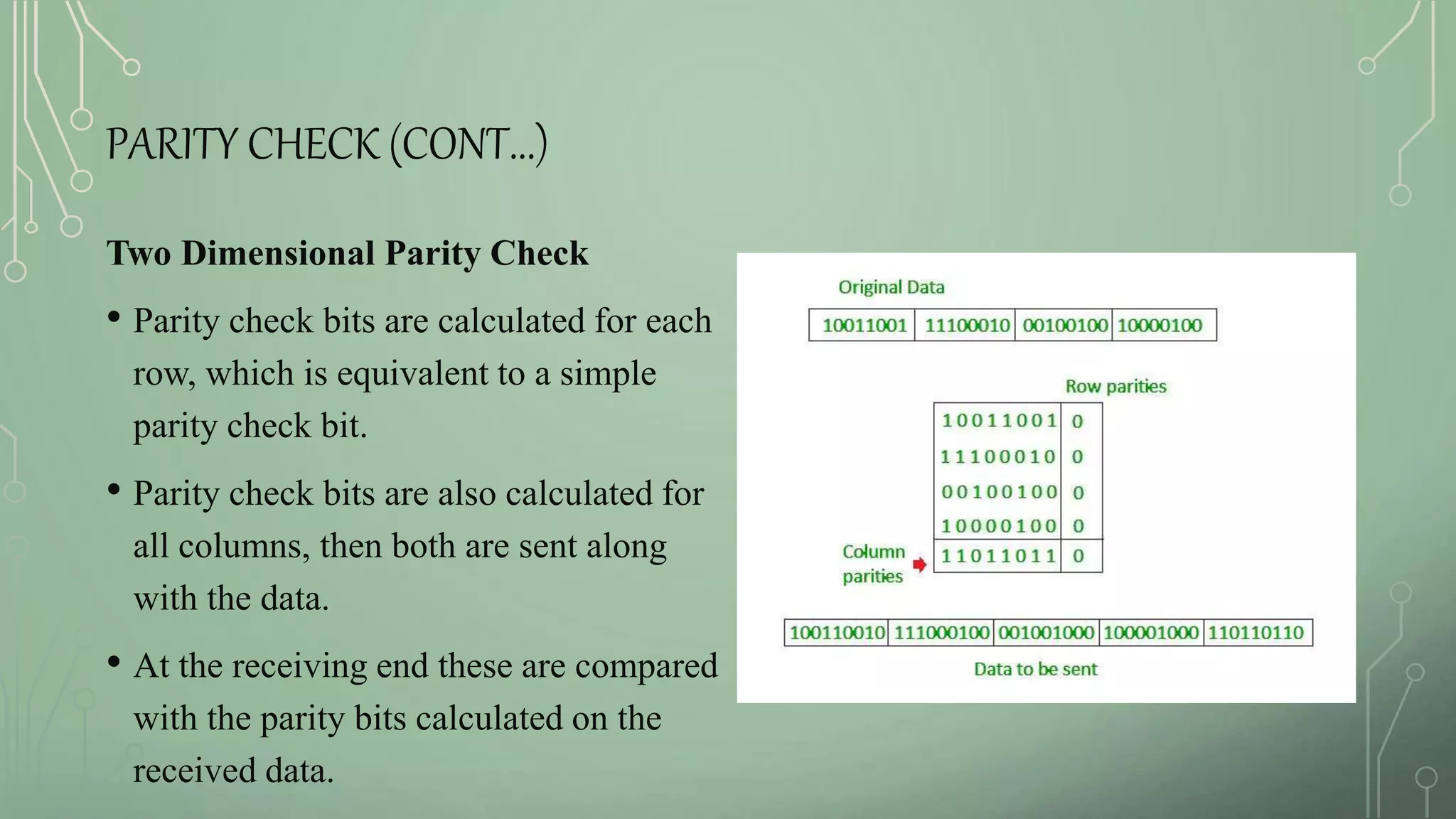
1. UDP checksum, CRC, and parity check for error detection.
2. Congestion control mechanisms like windowing and acknowledgments to prevent network overload.
3. Token ring and FDDI network topologies that use token passing for media access control.
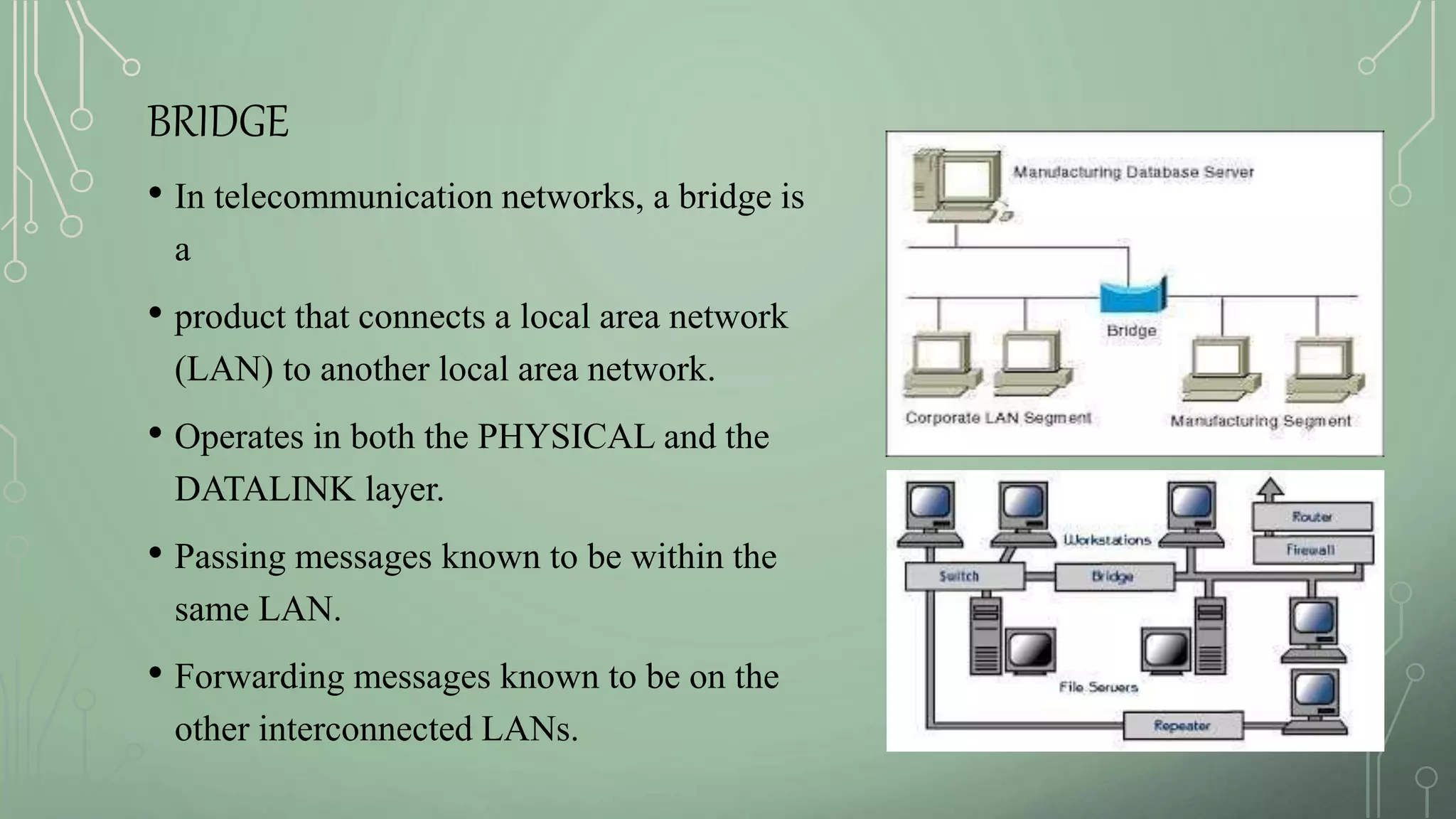
4. Bridges and LAN emulation that allow connections between different network types.
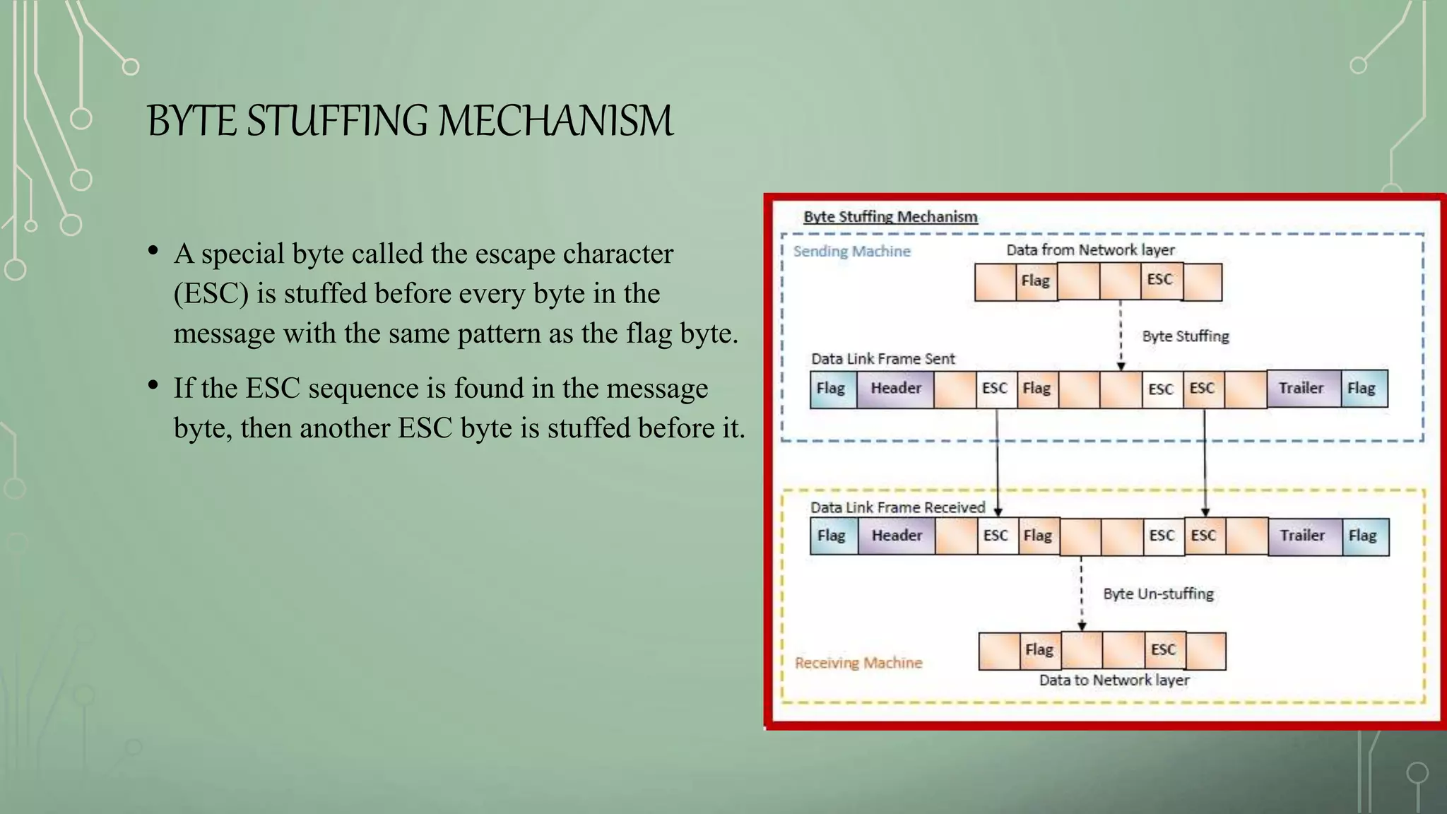
5. Bit and byte stuffing techniques used to frame data link layer packets for transmission.