Download to read offline

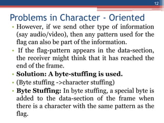
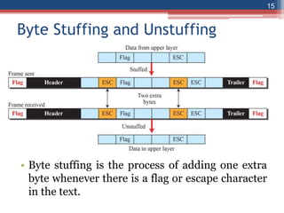
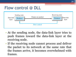
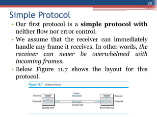
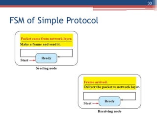
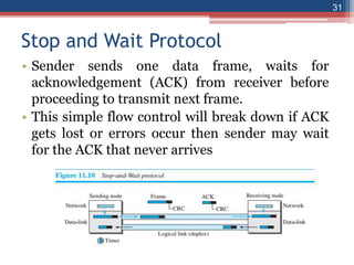
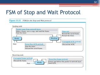


This document provides an overview of the data link layer and media access control. It discusses topics like link-layer addressing, data link layer protocols, framing, error control, flow control, and common data link layer protocols. It provides examples of finite state machines to illustrate the simple protocol and stop-and-wait protocol. Key points covered include how framing separates messages, the use of bit stuffing to avoid flag patterns in data, flow control using buffers, and acknowledgments for error control.