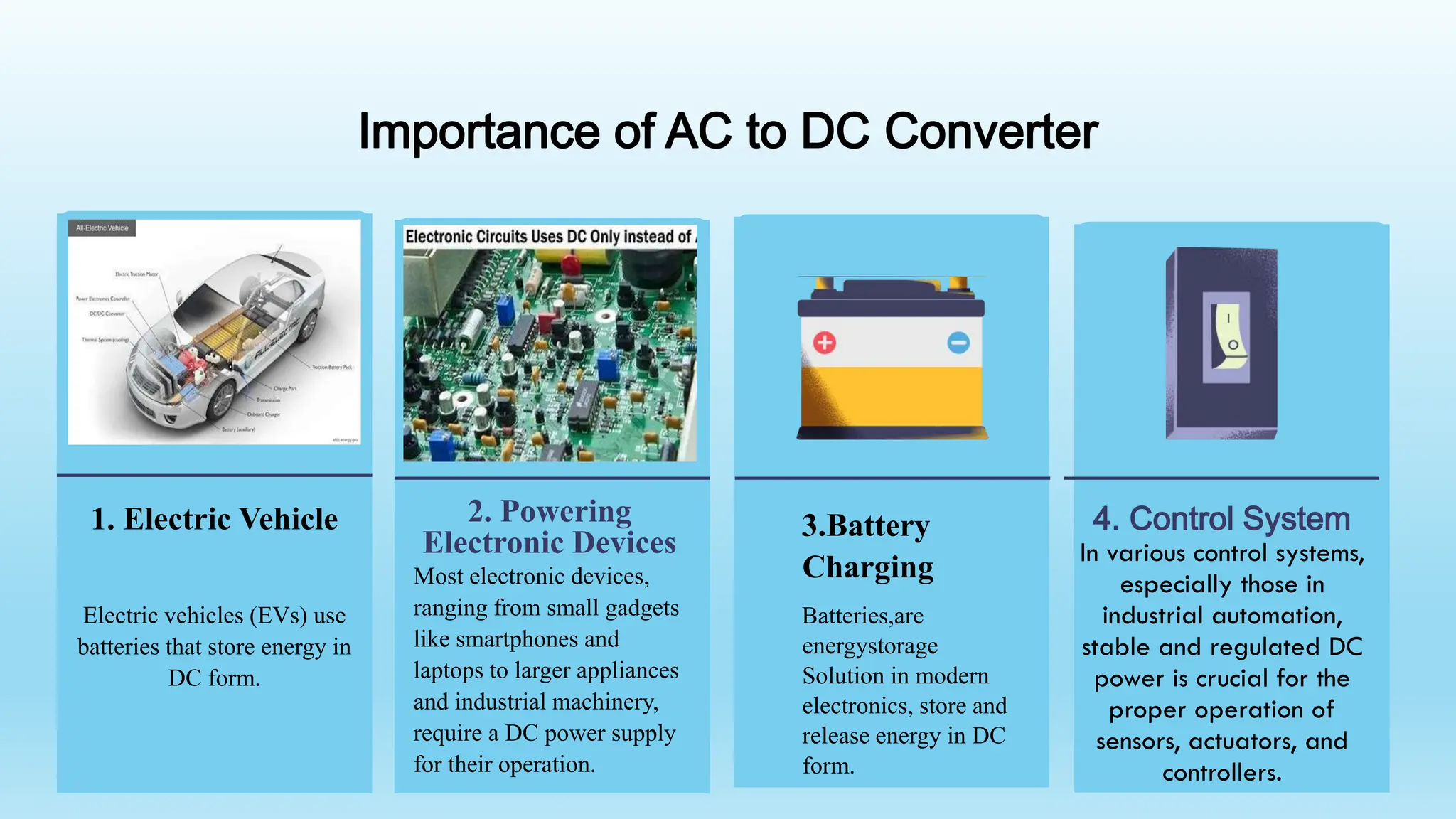
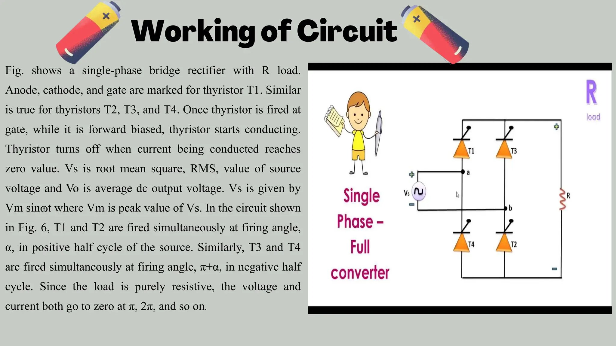
Presented By –
Ayush Kumar (2101100200023)
Ayush Kumar (2101100200024)
Akshansh Roy (2101100200012)
Aditya Tiwari (2101100200010)
Akshansh (2101100200011)
Submitted to – Miss Farhat Ara
Assistant Professor
Department of Electrical Engineering
Institute of Engineering & Rural Technology, Prayagraj
Single Phase AC to DC Converter on
MATLAB Simulink”
TABLE OF CONTENTS
INTRODUCTION IMPORTANCE OF
PROJECT
PRINCIPLES OF
CONVERTER WORKING
MAJOR COMPONENTS
WITH DEFINITION
CONCLUSION &
RESULT
04 05 06
01 02 03
single-phase AC to DC converter is an electronic device that converts AC voltage to DC voltage.
is widely used in power electronics applications such as battery chargers, DC motor drives, and
enewable energy systems. In this context, a MATLAB simulation can be used to model and analyze
he performance of a single-phase AC to DC converter using thyristors. The simulation can be
erformed using mathematical modeling, detailed modeling, or average modeling approaches.
armonic analysis of the circuit can also be carried out. The MATLAB/Simulink and
imPowerSystems software can be used to perform these models. The simulation results can be used
o optimize the design of the converter and to evaluate its performance under different operating
onditions.
Introduction
Importance of AC to DC Converter
1. Electric Vehicle
Electric vehicles (EVs) use
batteries that store energy in
DC form.
3.Battery
Charging
Batteries,are
energystorage
Solution in modern
electronics, store and
release energy in DC
form.
2. Powering
Electronic Devices
Most electronic devices,
ranging from small gadgets
like smartphones and
laptops to larger appliances
and industrial machinery,
require a DC power supply
for their operation.
4. Control System
In various control systems,
especially those in
industrial automation,
stable and regulated DC
power is crucial for the
proper operation of
sensors, actuators, and
controllers.
2. AC Voltage Source
The AC Source block represents the alternating
current (AC) input to your system. You can specify
parameters such as voltage magnitude, frequency,
and phase angle to simulate the AC input
waveform.
3. RLC Branch
The RLC Series Branch block represents the
electrical components in your system,
including resistors (R), inductors (L), and
capacitors (C). In the context of your project,
this block could be used to model the filtering
and energy storage elements in the converter
circuit.
1. Thyristor
Thyristors are semiconductor devices
that act as controlled rectifiers, allowing
current flow in one direction when
triggered. The block helps model the
controlled rectification process in your
converter.
 The principle of AC to DC conversion involves altering the direction of
current flow from alternating to direct. This is achieved by using
semiconductor devices called diodes. Diodes allow current to flow in one
direction only, blocking it in the opposite direction. There are two main
types of AC to DC conversion: half-wave rectification and full-wave
rectification
 Full-wave rectification utilizes both halves of the AC waveform. A diode
bridge configuration, consisting of four diodes, is commonly used for
full-wave rectification. This arrangement ensures that current flows in the
same direction during both the positive and negative half-cycles,
producing a smoother DC output.
Fig. shows a single-phase bridge rectifier with R load.
Anode, cathode, and gate are marked for thyristor T1. Similar
is true for thyristors T2, T3, and T4. Once thyristor is fired at
gate, while it is forward biased, thyristor starts conducting.
Thyristor turns off when current being conducted reaches
zero value. Vs is root mean square, RMS, value of source
voltage and Vo is average dc output voltage. Vs is given by
Vm sinɷt where Vm is peak value of Vs. In the circuit shown
in Fig. 6, T1 and T2 are fired simultaneously at firing angle,
α, in positive half cycle of the source. Similarly, T3 and T4
are fired simultaneously at firing angle, π+α, in negative half
cycle. Since the load is purely resistive, the voltage and
current both go to zero at π, 2π, and so on.
In the pursuit of understanding and implementing a single-phase AC to DC converter utilizing four
thyristors within the MATLAB Simulink environment, this project has yielded valuable insights into the realm
of controlled rectifiers, thyristor-based power electronics, and simulation methodologies. Through a systematic
exploration of theoretical concepts, simulation modeling, and analysis of results, several key conclusions can be
drawn.
Achievements and Successes
The project successfully demonstrated the capability of thyristors in efficiently controlling the conversion of
single-phase AC to DC. By manipulating the firing angle, we achieved precise regulation of power delivered to
the load. The simulation results showcased the converter's ability to provide a stable and controlled DC output,
emphasizing the practical significance of thyristor-based controlled rectifiers.
Any QUESTION ?
THANK YOU

ac to dc converter on matlab simulink.pptx

  • 1.
    Presented By – AyushKumar (2101100200023) Ayush Kumar (2101100200024) Akshansh Roy (2101100200012) Aditya Tiwari (2101100200010) Akshansh (2101100200011) Submitted to – Miss Farhat Ara Assistant Professor Department of Electrical Engineering Institute of Engineering & Rural Technology, Prayagraj Single Phase AC to DC Converter on MATLAB Simulink”
  • 2.
    TABLE OF CONTENTS INTRODUCTIONIMPORTANCE OF PROJECT PRINCIPLES OF CONVERTER WORKING MAJOR COMPONENTS WITH DEFINITION CONCLUSION & RESULT 04 05 06 01 02 03
  • 3.
    single-phase AC toDC converter is an electronic device that converts AC voltage to DC voltage. is widely used in power electronics applications such as battery chargers, DC motor drives, and enewable energy systems. In this context, a MATLAB simulation can be used to model and analyze he performance of a single-phase AC to DC converter using thyristors. The simulation can be erformed using mathematical modeling, detailed modeling, or average modeling approaches. armonic analysis of the circuit can also be carried out. The MATLAB/Simulink and imPowerSystems software can be used to perform these models. The simulation results can be used o optimize the design of the converter and to evaluate its performance under different operating onditions. Introduction
  • 4.
    Importance of ACto DC Converter 1. Electric Vehicle Electric vehicles (EVs) use batteries that store energy in DC form. 3.Battery Charging Batteries,are energystorage Solution in modern electronics, store and release energy in DC form. 2. Powering Electronic Devices Most electronic devices, ranging from small gadgets like smartphones and laptops to larger appliances and industrial machinery, require a DC power supply for their operation. 4. Control System In various control systems, especially those in industrial automation, stable and regulated DC power is crucial for the proper operation of sensors, actuators, and controllers.
  • 5.
    2. AC VoltageSource The AC Source block represents the alternating current (AC) input to your system. You can specify parameters such as voltage magnitude, frequency, and phase angle to simulate the AC input waveform. 3. RLC Branch The RLC Series Branch block represents the electrical components in your system, including resistors (R), inductors (L), and capacitors (C). In the context of your project, this block could be used to model the filtering and energy storage elements in the converter circuit. 1. Thyristor Thyristors are semiconductor devices that act as controlled rectifiers, allowing current flow in one direction when triggered. The block helps model the controlled rectification process in your converter.
  • 6.
     The principleof AC to DC conversion involves altering the direction of current flow from alternating to direct. This is achieved by using semiconductor devices called diodes. Diodes allow current to flow in one direction only, blocking it in the opposite direction. There are two main types of AC to DC conversion: half-wave rectification and full-wave rectification  Full-wave rectification utilizes both halves of the AC waveform. A diode bridge configuration, consisting of four diodes, is commonly used for full-wave rectification. This arrangement ensures that current flows in the same direction during both the positive and negative half-cycles, producing a smoother DC output.
  • 7.
    Fig. shows asingle-phase bridge rectifier with R load. Anode, cathode, and gate are marked for thyristor T1. Similar is true for thyristors T2, T3, and T4. Once thyristor is fired at gate, while it is forward biased, thyristor starts conducting. Thyristor turns off when current being conducted reaches zero value. Vs is root mean square, RMS, value of source voltage and Vo is average dc output voltage. Vs is given by Vm sinɷt where Vm is peak value of Vs. In the circuit shown in Fig. 6, T1 and T2 are fired simultaneously at firing angle, α, in positive half cycle of the source. Similarly, T3 and T4 are fired simultaneously at firing angle, π+α, in negative half cycle. Since the load is purely resistive, the voltage and current both go to zero at π, 2π, and so on.
  • 10.
    In the pursuitof understanding and implementing a single-phase AC to DC converter utilizing four thyristors within the MATLAB Simulink environment, this project has yielded valuable insights into the realm of controlled rectifiers, thyristor-based power electronics, and simulation methodologies. Through a systematic exploration of theoretical concepts, simulation modeling, and analysis of results, several key conclusions can be drawn. Achievements and Successes The project successfully demonstrated the capability of thyristors in efficiently controlling the conversion of single-phase AC to DC. By manipulating the firing angle, we achieved precise regulation of power delivered to the load. The simulation results showcased the converter's ability to provide a stable and controlled DC output, emphasizing the practical significance of thyristor-based controlled rectifiers.
  • 11.
  • 12.