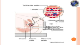
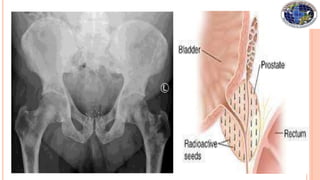
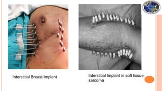
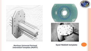
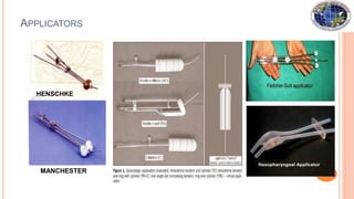
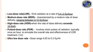
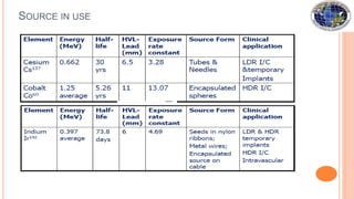
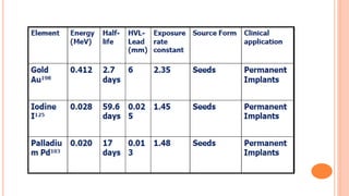
Brachytherapy involves placing small radioactive sources inside or near a tumor. It allows a high radiation dose to be delivered to the tumor while sparing surrounding normal tissues. There are several types of brachytherapy classified by source placement (interstitial, intracavitary), loading pattern (pre-loading, after-loading), dose rate (LDR, HDR), and duration of implant (temporary, permanent). Common radioactive sources used include cesium-137, iridium-192, and iodine-125 seeds. Brachytherapy provides advantages of high tumor control with minimal side effects due to rapid dose fall-off and short treatment times.